二竖维护手册(参考版)
二级维护流程.pdf

1分 1分 1分
1分 1分
1分 1分
1分 1分
姓名 __________ __,
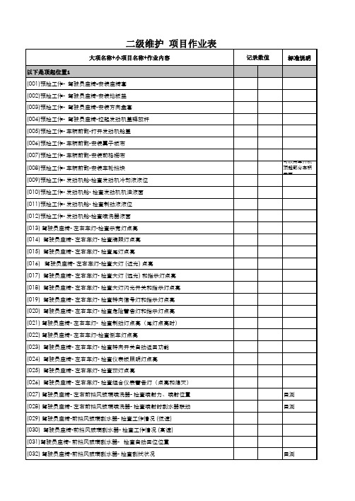
维护项目评分标准 [ 顶起位置 3 (1/2)]
参赛号 _______ ____
裁判签字 ____________
定期保养项目 ( 本页共有 25 项)
作业 顺序
比赛项目
发动机机油 ( 排放 )
(088) 检查是否漏油 ( 发动机各部位的配合表
(134) 前悬架横梁加强件×前悬架横梁
(135) 横拉杆端头锁止螺母(检查)
(136) 横拉杆端头×转向节(检查)
(137) 转向机壳×前横梁
后悬架
(138) 后桥横梁总成×车身
1
(139) 制动分泵×背板
(140) 后减振器×后桥横梁总成
其他
(141) 排气管
(142) 燃油箱
1分 1分 1分 1分 1分 1分 1分 1分 1分 1分
分 1分 1分
1分 1分
姓名 __________ __,
维护项目评分标准 [ 顶起位置 4]
参赛号 _______ ____
裁判签字 ____________
定期保养项目 ( 本页共有 16 项)
作业
比赛项目
配分
顺序
制动系统
车轮轴承( 4 个)
(143) 检查有无摆动
2分
(144) 检查转动状况和噪声
(078) 检查工作情况(顶灯和指示灯工作情况)
1分
螺母和螺栓
裁判签字 ____________
评分标准
完成得 分
(079) 检查座椅安全带的螺栓和螺母是否松动 (080) 检查座椅的螺栓和螺母是否松动 (081) 检查车门的螺栓和螺母是否松动 前部 前悬架 (082) 检查减振器的阻尼状态 (083) 检查车辆倾斜度 灯 (084) 检查安装状况 (085) 检查是否损坏和有污垢 发动机舱 (086) 检查发动机舱盖的螺栓和螺母是否松动 (087) 拆卸机油加注口盖
设备维护、保养手册(标准版)
设备维护、保养手册(标准版)Safety management is an important part of production management. Safety and production are inthe implementation process( 安全管理 )单位:_________________________姓名:_________________________日期:_________________________精品文档 / Word文档 / 文字可改设备维护、保养手册(标准版)一、设备保养润滑基本标准:1.所有设备的润滑部位,必须使用本工作手册规定的润滑油,不得使用其它规格、牌号的润滑油;不得将不同规格的润滑油混合使用;不得注入使用不清洁、已变质、带腐蚀性的润滑油。
2.清洗更换润滑油标准:将设备内残存的污油清除干净,用柴油或汽油清洗机械部件和轴承,然后再加入新润滑油。
残存污油经检验后,品质符合要求时,污油必须经清理过滤,才能继续使用。
3.初次使用的新设备,运转使用15天左右,必须更换润滑油。
4.使用润滑油的部位,润滑油注入量为部位容积的1/3-1/2:低速运转的,加润滑脂量为2/3;高速运转的,加润滑脂量为1/2。
5.六个月以上没有使用的设备,在重新开机使用前,其润滑部位必须更换润滑油。
6.加油时间和责任工作标准:6.1每班接班后两小时内为当班加油时间,由设备操作工负责加油。
6.2每天白班上午8点至10点为当天的加油时间,由设备操作工负责加油。
6.3小修时的设备加油或更换润滑油工作,由设备操作工负责。
二、通用设备的保养润滑标准:1.摆线针轮减速机的润滑:1.1润滑油选用32#机械油。
1.2润滑油注入量为减速机容积的1/3-1/2,经常观察油位,高度不足时,补充相同牌号的润滑油。
1.3每天连续运行10小时以上者,每3个月(中修时)更换润滑油一次;每天连续运行不足10小时者,每年(大修时)更换滑油一次。
二级维护作业表
客运车辆二级维护工艺规程

5、清洁油水分离器,每年更换油水分离器滤芯
5
曲轴箱通风装置(PVC阀)
检查、清洁
清洁通畅,连接可靠,不漏气,单向阀工作有效,无卡滞
6
散热器、风扇
护风罩、水泵节温器
传动带
1、检查冷却系统密封情况、液面高度、水泵、护风罩、风扇
2、检视传动带外观,调整传动带挠度
1、检查密封状况和操作机构清洁通气孔
2、紧固各连接螺栓
3、检查变速箱、主减速器的工作情况
1、变速器密封良好,通气孔畅通,操纵机构作用正常,无异响、跳档、乱档现象,换挡灵活,档位准确,各连接螺栓紧固可靠
2、变速助力泵不漏气,作用正常
3、主减速器运转平稳,无异响,主、被东齿轮啮合正常,啮合间隙不大于0.7mm
1、制动器底板不变形,制动器底板紧固螺栓拧紧力矩为:160~200N.m
2、突轮轴轴承润滑良好,突轮轴转动灵活,无卡滞,轴向窜动量不大于1mm,与衬套间隙不大于0.3mm
3、制动气塞无变形,膜片无裂纹或老化现象,制动软管完好无损
3、检查桥壳、螺母及油封
1、后桥壳、半轴套管无裂纹及弯曲变形,配合无松动,套管轴头螺纹无2牙以上损伤,与螺母配合无径向间隙,套管与轴承配合间隙不大于0.1mm
制动管路
制动踏板
1、检查制动踏板自由行程
2、检查、紧固制动阀和管路接头
1、制动踏板自由行程为10~15mm
2、制动阀清洁,无裂纹,无漏气
3、管路接头连接可靠,无漏气、堵塞、轧扁现象
22
驻车制动
1、检查驻车制动性能
2、检查手控阀
1、20%坡度双向正反驻车可靠
2、手控阀上、下突轮表面涂润滑脂,不漏气,阻止阀关闭时的最低压力为240kPa
日常维护一级维护二级维护的内容

日常维护一级维护二级维护的内容下载提示:该文档是本店铺精心编制而成的,希望大家下载后,能够帮助大家解决实际问题。
文档下载后可定制修改,请根据实际需要进行调整和使用,谢谢!本店铺为大家提供各种类型的实用资料,如教育随笔、日记赏析、句子摘抄、古诗大全、经典美文、话题作文、工作总结、词语解析、文案摘录、其他资料等等,想了解不同资料格式和写法,敬请关注!Download tips: This document is carefully compiled by this editor. I hope that after you download it, it can help you solve practical problems. The document can be customized and modified after downloading, please adjust and use it according to actual needs, thank you! In addition, this shop provides you with various types of practical materials, such as educational essays, diary appreciation, sentence excerpts, ancient poems, classic articles, topic composition, work summary, word parsing, copy excerpts, other materials and so on, want to know different data formats and writing methods, please pay attention!日常维护一级维护二级维护的内容一、日常维护的内容日常维护是保持设备长期正常运转的重要环节,它包括了设备的日常巡检、清洁和润滑等工作。
维护说明书

Citrix Provisioning2209ContentsCitrix Provisioning22093新增功能3已修复的问题4已知问题和注意事项5数据治理6第三方声明9弃用9系统要求和兼容性10许可22为虚拟磁盘配置Microsoft批量许可27体系结构34组件37产品实用程序41管理员角色42集合43 Citrix Provisioning控制台43安装Citrix Provisioning软件组件45安装前需执行的任务47网络组件61安装服务器组件72无提示运行配置向导73安装控制台组件79准备好主目标设备以便构建映像80使用映像向导创建虚拟磁盘83升级86服务器93虚拟磁盘95配置104控制台104场111服务器126设备集合141目标设备143获取引导程序文件151使用Boot Device Management实用程序155通过流技术推送Linux目标设备157关于SAN策略163在目标设备上使用状态托盘164虚拟磁盘167配置虚拟磁盘以实现Active Directory管理176为目标设备分配虚拟磁盘182 Microsoft Azure上的Citrix Provisioning183 Google云端平台上的Citrix Provisioning242 AWS上的Nutanix中的Citrix Provisioning285 VMware云和合作伙伴解决方案287导出设备向导307使用流VM设置向导325使用Citrix Virtual Apps and Desktops设置向导将虚拟桌面部署到VM328预配启用了vGPU的Citrix Virtual Apps and Desktops计算机343 Citrix Provisioning Accelerator346统一可扩展固件接口(UEFI)预启动环境351 Citrix Provisioning由Citrix Cloud进行管理354在目录创建过程中支持多个区域361管理363场364站点364服务器366存储369设备集合373目标设备375虚拟磁盘393为标准虚拟磁盘映像选择写入缓存目标位置398支持复制的虚拟磁盘存储399导出和导入虚拟磁盘401释放虚拟磁盘锁403复制和粘贴虚拟磁盘属性403将现有虚拟磁盘添加到虚拟磁盘池或存储中404备份虚拟磁盘404查看虚拟磁盘使用情况404删除差异磁盘上的缓存405向目标设备分配虚拟磁盘和版本406更新虚拟磁盘410报废或删除虚拟磁盘421虚拟磁盘故障排除421视图424管理角色428高级概念431通过将SQL Server限制到TLS1.2启用安全连接431启用SQL Server AlwaysOn多子网故障转移432 SQL Basic可用性组433同一主机内的存储迁移434管理以实现高可用性435脱机数据库支持435数据库镜像437用于SQL Server2012、2014、2016、2017和2019的SQL AlwaysOn438 Provisioning服务器故障转移439配置使用共享存储的高可用性环境440为实现高可用性配置引导文件442故障排除444日志记录445审核446 API448 CIS问题报告452将VM迁移到新的托管资源457Citrix Provisioning2209December15,2022Citrix Provisioning是软件流技术推送技术,用于通过共享桌面映像向多个虚拟桌面端点传送修补程序、更新和其他配置信息。
2112 Floor Light 维护记录与操作说明书

2112 Floor LightOPERATIONS/MAINTENANCE MANUAL For Parts or Technical Assistance1-800-327-0770Table of Contents. . . . . . . . . . . . . . . . . . . . . . . . . . . . . . . . . . . . . . . . . . . . . . . . . . . . . . . . . . . . . . . . . . . . . . . Assembly Instructions2. . . . . . . . . . . . . . . . . . . . . . . . . . . . . . . . . . . . . . . . . . . . . . . . . . . . . . . . . . Counterweight Assembly Illustration3Operating Instructions. . . . . . . . . . . . . . . . . . . . . . . . . . . . . . . . . . . . . . . . . . . . . . . . . . . . . . . . . . . . . . . . . . . .Hi/Lo Intensity Control4. . . . . . . . . . . . . . . . . . . . . . . . . . . . . . . . . . . . . . . . . . . . . . . . . . . . . . . . . . . . . . . . . . . . . . . . . . .Focus Control4. . . . . . . . . . . . . . . . . . . . . . . . . . . . . . . . . . . . . . . . . . . . . . . . . . . . . . . . . . . .Removable Positioning Handles4. . . . . . . . . . . . . . . . . . . . . . . . . . . . . . . . . . . . . . . . . . . . . . . . . . . . . . . . . . . . .Spare Bulb And Fuse Storage4Maintenance Instructions. . . . . . . . . . . . . . . . . . . . . . . . . . . . . . . . . . . . . . . . . . . . . . . . . . . . . . . . . . . .Counterweight Assembly Cover5. . . . . . . . . . . . . . . . . . . . . . . . . . . . . . . . . . . . . . . . . . . . . . . . . . . . . . . . . . . . . . . . . . . . . . . .Bulb Replacement5. . . . . . . . . . . . . . . . . . . . . . . . . . . . . . . . . . . . . . . . . . . . . . . . . . . . . . . . . . . . . . . . . . . . . . .Fuse Replacement5. . . . . . . . . . . . . . . . . . . . . . . . . . . . . . . . . . . . . . . . . . . . . . . . . . . . . . . . . . . . . . . . . . . . . . . . Electrical Schematic6Assembly Drawings and Parts Lists. . . . . . . . . . . . . . . . . . . . . . . . . . . . . . . . . . . . . . . . . . . . . . . . . . . . . . . . . . . . . . . .Floor Light Final Assembly7. . . . . . . . . . . . . . . . . . . . . . . . . . . . . . . . . . . . . . . . . . . . . . . . . . . . . . . . . . . . . . .Base Assembly with Casters8. . . . . . . . . . . . . . . . . . . . . . . . . . . . . . . . . . . . . . . . . . . . . . . . . . . . . . . . . . . . . . . . . .Counterweight Assembly9. . . . . . . . . . . . . . . . . . . . . . . . . . . . . . . . . . . . . . . . . . . . . . . . . . . . . . . . . . . . . . . . . . .Base Cover Assembly10. . . . . . . . . . . . . . . . . . . . . . . . . . . . . . . . . . . . . . . . . . . . . . . . . . . . . . . . . . . . . . . .Head/Arm Post Assembly11. . . . . . . . . . . . . . . . . . . . . . . . . . . . . . . . . . . . . . . . . . . . . . . . . . . . . . . . . . . . . . . . . . . . .Head/Arm Assembly12Focus Adjustment Ring Assembly13. . . . . . . . . . . . . . . . . . . . . . . . . . . . . . . . . . . . . . . . . . . . . . . . . . . . . . . . .. . . . . . . . . . . . . . . . . . . . . . . . . . . . . . . . . . . . . . . . . . . . . . . . . . . . . . . . . . . . . . . . . . . . . . . .Focus Assembly14. . . . . . . . . . . . . . . . . . . . . . . . . . . . . . . . . . . . . . . . . . . . . . . . . . . . . . . . . . . . . . . . . . . . . . . . .Lens Assembly15Handle Assembly16 . . . . . . . . . . . . . . . . . . . . . . . . . . . . . . . . . . . . . . . . . . . . . . . . . . . . . . . . . . . . . . . . . . . . . . .. . . . . . . . . . . . . . . . . . . . . . . . . . . . . . . . . . . . . . . . . . . . . . . . . . . . . . . . . . . . . . . . . . . . . . . . . .Arm Assembly17. . . . . . . . . . . . . . . . . . . . . . . . . . . . . . . . . . . . . . . . . . . . . . . . . . . . . . . . . . . . . . . . . . . . . . . . .Yoke Assembly18. . . . . . . . . . . . . . . . . . . . . . . . . . . . . . . . . . . . . . . . . . . . . . . . . . . . . . . . . . . . . . . . .Tension Spring Assembly19. . . . . . . . . . . . . . . . . . . . . . . . . . . . . . . . . . . . . . . . . . . . . . . . . . . . . . . . . . . . . . . . . . . . . . . . . .Hub Assembly20. . . . . . . . . . . . . . . . . . . . . . . . . . . . . . . . . . . . . . . . . . . . . . . . . . . . . . . . . . . . . . . . . .Switch Cover Assembly21. . . . . . . . . . . . . . . . . . . . . . . . . . . . . . . . . . . . . . . . . . . . . . . . . . . . . . . . . . . . . . . . .Rotary Switch Assembly22. . . . . . . . . . . . . . . . . . . . . . . . . . . . . . . . . . . . . . . . . . . . . . . . . . . . . . . . . . . . . . . . . . . . . . . . . .Post Assembly23. . . . . . . . . . . . . . . . . . . . . . . . . . . . . . . . . . . . . . . . . . . . . . . . . . . . . . . . . . . . . . . . . . . . Replacement Parts List24 Limited Warranty. . . . . . . . . . . . . . . . . . . . . . . . . . . . . . . . . . . . . . . . . . . . . . . . . . . . . . . . . . . . . .Obtaining Parts and Service25Supplemental Warranty Coverage25. . . . . . . . . . . . . . . . . . . . . . . . . . . . . . . . . . . . . . . . . . . . . . . . . . . . . . . . .. . . . . . . . . . . . . . . . . . . . . . . . . . . . . . . . . . . . . . . . . . . . . . . . . . . . . . . . . . . . . . . . . . . . .Return Authorization26. . . . . . . . . . . . . . . . . . . . . . . . . . . . . . . . . . . . . . . . . . . . . . . . . . . . . . . . . . . . . . . . . .Freight Damage Claims26Assembly InstructionsThe Adel Minor Surgery Light is packed in two shipping cartons and should be assembled using the following instructions:NOTEAssemble the light on soft, protective material to avoid marring the finish of the light.Required Tools:Phillips Screwdriver3/4” Wrench HammerAssembly Instructions:1. Remove the base, counterweight assembly and head/post assembly from their cartons. Locate the pin-stripe tape on the post (tapered end) and on the base next to the center hole.2. Lay the head/post assembly on the floor with the light head above the post (pinstripe on top). Insert theend of the post into the base by threading the wires through the base center hole. Rotate the post until the pinstripe tape on the base and post are aligned. T ap the bottom of base with a hammer to secure it on the post.3. Attach the counterweight assembly by screwing the 1/2” bolt into the end of the post. The counterweightassembly hangs between the two bottom legs of the base opposite the pinstripe tape. Route the electric wires past the 1/2” bolt into the counterweight assembly area. Support the counterweight assembly with one hand while turning the 1/2” bolt.NOTEThe tab on the counterweight assembly must enter the center hole of the base.4. Ensure the pinstripe tape on the head/post assembly and base are still in alignment. Remove the tape.5. Place the light in the upright position.Counterweight Assembly Instructions (see counterweight assembly illustration on page 3):1. Remove the ground screw and the two washers from the left side of the counterweight assembly. Con-nect the single green ground wire using the following order: screw, washer, wire terminal, washer.2. Attach the black wire to the tab marked #6 on the transformer.3. Attach the red wire to the terminal strip tab with the red wire from the transformer.4. Attach the white wire to the terminal strip opposite the red wires.Transformer Cover and Positioning Handles Assembly Instructions:1. Slide the transformer cover under the edge of the leg base and snap it into position by applying pressureon the outer edge. Fasten it with the #8-32 screw provided. If the cover does not slide under the edge, loosen the bolt at the end of the post, slide the cover under the edge, and re-tighten the bolt.2. Install the positioning handles into the handle sockets on the light head until the spring loaded buttonsnaps into the locking position.Counterweight AssemblyOperating InstructionsHI/LO INTENSITY CONTROLA single knob located on one side of the arm-to-post joint turns the light on and adjusts the light intensity to a low or high level. Select the intensity that provides the best tissue discrimination and minimum eye strain. FOCUS CONTROLThe knob located on the back of the light head provides an adjustment to obtain an optimum area of shadow-less illumination. Readjustment may be required when the distance from the tissue surface changes. the focus knob provides full adjustment in 1 1/2 turns.CAUTIONDo not force the focus knob after it stops turning. Damage to the focusing mechanism may result if the knob is turned more than 1 1/2 turns.REMOVABLE POSITIONING HANDLESA positioning handle is located on each side of the light head. The handles can be easily removed by pressing the spring loaded button and pulling away from the light head. The handles can be autoclaved and reinstalled using sterile techniques.Reorder number (set of 2) - 8815-011-100SPARE BULB AND FUSE STORAGEAn extra bulb and fuse are located in the counterweight assembly at the base of the floor light.Bulb reorder number - 8815-004-500Fuse reorder number - 8815-003-200See page 5 for replacement procedures.Maintenance InstructionsCOUNTERWEIGHT ASSEMBLY COVERWARNINGUnplug the power cord before removing the counterweight assembly cover or personal injury could result. For both fuse and bulb replacement, it is necessary to remove the triangular counterweight assembly cover at the base of the light.To remove the cover: Remove the #8-32 screw. Slightly loosen the 1/2” bolt at the bottom of the post and pull the counterweight assembly cover out away from the center post. This uncovers the transformer, fuse holder, extra fuse and extra bulb and provides access to some of the wiring.When replacing the counterweight assembly cover, DO NOT over-tighten the 1/2” bolt. Light but firm pres-sure should be applied to hold the cover up against the lip of the leg base.BULB REPLACEMENTWARNINGTurn source power off before replacing the bulb or personal injury could result.1. Remove the front shroud.2. Remove the lens from the lens clips. Be careful not to over-bend the clips when removing the lens. Ifthe clips do get over-bent, be sure to straighten them before reinstalling the lens.3. Be sure the burned out bulb is cool, then remove it.4. Install the new bulb, using a clean cloth to handle the bulb. Do not touch the bulb with your bare fingersbecause skin oils cause premature failure of the bulb. Do not move the bulb from side-to-side while installing it; push it straight in.5. Replace the lens, making sure all four clips make secure contact with the lens.6. Replace the shroud.7. Turn the power back on.8. Turn light on to HI to check the light’s performance.Bulb reorder number - 8815-035-800FUSE REPLACEMENTWARNINGTurn the source power off before replacing the fuse or personal injury could result.The spare fuse is mounted next to the transformer in the counterweight assembly at the base of the floor light (see counterweight assembly illustration on page 3).Remove the blown fuse from the fuse holder and replace it with the spare fuse.Fuse reorder number - 8815-003-200Electrical Schematic120 VOLTS, 60 Hz, 1 1/4 AMP RATING105 TO 135 VAC OPERATING RANGEFloor Light Final AssemblyAssembly part number 8815-040-100(reference only)Item Part No.Part Name Qty.1(page 8)Base Assembly with Casters12(page 11)Head/Arm Post Assembly13(page 10)Base Cover Assembly14(page 9)Counterweight Assembly158815-005-700Phillips Hd. Screw168815-040-500Hub Cover18815-040-200 Base Assembly with CastersItem Part No.Part Name Qty.18815-042-800Lamp Base1 28801-790-000Caster3 38815-020-102Locking Caster2Counterweight AssemblyAssembly part number 8815-000-200Item Part No.Part Name Qty.Item Part No.Part Name Qty. 10059-154-000Fuse Block1148815-001-300Counterweight1 21502-080-002Red Hook-Up Wire35”158815-010-500Transformer1 38815-001-100Wire Anchor Clip1168815-002-200Pan Hd. Screw1 48815-007-000Phillips Hd. Screw2178815-004-800Resistor1 58815-005-500Int. Tooth Lock Washer3188800-500-300Ring Terminal3 68815-010-300Tab2198801-620-000Clip2 78815-009-600Terminal Strip1208815-004-500Exam Light Bulb1 80034-202-000Insulation Sleeve3”211502-001-003 1.25 Amp. Slo-Blo Fuse2 91502-080-003Red Hook-Up Wire35”238815-012-600Push Nut1 108815-012-700Phillips Hd. Screw4248815-012-500Hex Hd. Cap Screw1 118815-005-600Int. Tooth Lock Washer6258815-005-800Ext. Tooth Lock Washer1 128839-792-600Power Cord1278815-005-700Phillips Hd. Screw1 138815-001-400Strain Relief18815-040-400 Base Cover AssemblyItem Part No.Part Name Qty. 18815-040-600Counterweight Cover1 28815-000-800Light Serial No. Label1 38800-840-700Numerical Serial No. Label1 41502-001-004Caution Label1Head/Arm Post AssemblyAssembly part number 8815-040-300(reference only)Item Part No.Part Name Qty.1(page 23)Light Post Assembly128815-003-000Clear Button Bumper43(page 12) Head/Arm Assembly14(page 21)Switch Cover Assembly158800-840-600Adel Label168815-007-000Phillips Head Screw178815-005-500Star Lock Washer388800-500-300Ring Terminal198815-029-400Green Ground Tape1108815-002-600Male Connector2118815-025-600Cable Tie1128815-011-400Knob113(page 16)Handle Assembly2141502-001-005Burn Caution Label1Head/Arm AssemblyAssembly part numberSTEP 1STEP 2STEP 3 8815-040-800 (reference only)Item Part No.Part Name Qty.Item Part No.Part Name Qty. 1(page 17)Light Arm Assembly1138815-008-900Plastic Screw3 2(page 13)Focus Adj. Ring Ass’y1148815-004-000Thumb Screw Knob2 38815-014-000Phillips Hd. Screw3158815-041-800Handle Mtg. Bracket2 48815-018-400Phillips Hd. Screw1168815-005-500Int. Tooth Lock Washer8 58815-019-200Closed End Connector3178815-003-700Hex Hd. Cap Screw4 68815-041-400Outer Housing1188815-007-000Round Hd. Screw4 78815-016-800Stand Off6198815-028-000Lens Clip4 88815-041-500Vent Ring2208815-009-800Coated Mirror1 98815-014-400Round Threaded Spacer3218815-016-300Front Heat Shield1 108815-016-000Spacer3228815-004-500Bulb1 118815-041-600Cap Baffle123(page 15)Lens Assembly1 128815-042-500Focus Cover1248815-041-900Lens Mount Shroud1Focus Adjustment Ring AssemblyAssembly part number8815-041-300 (reference only)Item Part No.Part Name Qty.18815-042-200Plastic Ring128815-006-200Inner Housing138815-003-900Hex Nut348815-014-800Flat Washer458815-013-900Stud368815-007-000Round Hd. Screw278800-500-300Ring Terminal188815-005-500Lock Washer498815-009-500Spacer310(page 14)Light Focus Assembly1118815-009-400Thermal Shield1128815-013-000Ground Wire 5.83’138815-013-800Spacer3148815-029-400Ground Tape2”158815-019-900Pem Fastener38815-030-000 Focus Assembly Assembly part number 8815-032-700 (reference only)Item Part No.Part Name Qty.18815-002-000Set Screw Collar128808-319-600Belleville Spring138800-210-000Flange Bushing248815-003-700Hex Hd. Cap Screw358815-005-500Int. Tooth Lock Washer368815-019-400Bulb Mounting Plate178815-025-300Screw188815-014-200Hex Socket Screw198815-006-100Focusing Hub1108815-012-800Focus Adj. Screw Ass’y1118815-007-200Socket Mtg. Block1128815-016-800Spacer1138815-010-800Lamp Socket1148815-004-100Phillips Hd. Screw28815-028-100 Lens AssemblyAssembly part number 8815-032-600 (reference only)Item Part No.Part Name Qty.18815-002-200Pan Hd. Screw1 28815-028-600Lens1 38815-017-900Spacer1 48815-013-800Spacer1 58815-007-800Front Shield1 68815-014-000Round Hd. Screw18815-032-500 Handle AssemblyItem Part No.Part Name Qty.18815-016-900Snap Button Clip128815-011-300Light Handle1 Set of two handles = part number 8815-011-100Assembly part number 8815-041-200 (reference only)Item Part No.Part Name Qty.1(page 18)Yoke Assembly12(page 20)Hub Assembly138815-02-56-00Cable Tie148815-00-55-00Lock Washer158815-01-47-00Hex Jam Nut168815-01-78-00Soc. Hd. Screw178800-22-16-00Set Screw188815-00-67-00Counterbalance Cam198800-46-00-00Cable Clamp1Assembly part number8815-042-000 (reference only)Item Part No.Part Name Qty.18815-042-400Yoke Swing Arm12(page 19)Tension Spring Assembly138815-029-000Swing Arm Cable 4 Ft.48815-016-100Bearing Spacer158815-017-200Friction Spring168815-015-600Friction Block Pivot178815-007-900Head Pivot Block188815-013-500Rectangular Closure298815-017-800Button Hd. Screw1108815-031-300Nylon Plug1118815-018-400Phillips Hd. Screw18815-034-700 Tension Spring AssemblyItem Part No.Part Name Qty. 18815-007-400Spring Fastener1 28815-011-200Counterbalance Spring1 38815-007-300Spring Anchor1 48815-010-900Counterbalance Cable1 58815-019-200Closed End Connector1 68800-630-100Adhesive Tape3”Hub AssemblyAssembly part number 8815-042-100 (reference only)Item Part No.Part Name Qty.18815-013-700Cam Thrust Washer228815-042-300Hub238815-033-600Sleeve Stop148815-013-600Hub Thrust Washer158815-025-200Hub Pivot Pin168815-018-900Groove Pin1Switch Cover AssemblyAssembly part number 8815-040-900 (reference only)Item Part No.Part Name Qty.1(page 22)Rotary Switch Assembly1 28815-042-700Switch Hub Cover1 38815-011-400Focus Intensity Knob18815-029-600 Rotary Switch Assembly Assembly part number 8815-009-700 (reference only)Item Part No.Part Name Qty. 18815-005-1003-Position Rotary Switch1 28815-002-900Red Hook Up Wire3”38815-011-700White Hook Up Wire 1.5”48815-002-600Male Connector2 58815-002-700Female Connector1Post AssemblyAssembly part number 8815-040-700(reference only)Item Part No.Part Name Qty.18815-029-000Cable 5.528815-016-100Bearing Spacer138815-041-000Vertical Tube140500-030-049Cord Clip258801-730-000Pop Rivet468815-025-600Cable Tie178815-013-000Ground Wire 5.55’98800-500-300Ring Terminal2108815-002-700Insulated Female Terminal6Replacement Parts ListPART NAME PART NUMBER . . . . . . . . . . . . . . . . . . . . . . . . . . . . . . . . . . . . . . . . . . . . . . . . .Bulb, 70 Watt, 28 Volt8815-035-800 . . . . . . . . . . . . . . . . . . . . . . . . . . . . . . . . . . . . . . . . . . . . . . . . . . . .Base with Casters8815-040-200 . . . . . . . . . . . . . . . . . . . . . . . . . . . . . . . . . . . . . . . . . . . . . . . . . . . . . .Focus Stem Kit8815-030-000. . . . . . . . . . . . . . . . . . . . . . . . . . . . . . . . . . . . . . . . . . . . .Fuse, 1 1/4 Amp, Slo-Blo8815-003-200. . . . . . . . . . . . . . . . . . . . . . . . . . . . . . . . . . . . . . . . . . . . . .Knob, Focus/Off, Hi/Low 8815-011-400 Lens with Deflector8815-028-100 . . . . . . . . . . . . . . . . . . . . . . . . . . . . . . . . . . . . . . . . . . . . . . . . . . .. . . . . . . . . . . . . . . . . . . . . . . . . . . . . . . . . . . . . . .Light Handles, Pair (with Spring)8815-011-100 . . . . . . . . . . . . . . . . . . . . . . . . . . . . . . . . . . . . . . . . . . . . . . . . . . . . . . . . .Light Socket8815-010-800. . . . . . . . . . . . . . . . . . . . . . . . . . . . . . . . . . . . . .Light Socket Mount Block (Black)8815-007-200 . . . . . . . . . . . . . . . . . . . . . . . . . . . . . . . . . . . . . . . . . . . . . . . . . . . . . . . .Coated Mirror8815-009-800. . . . . . . . . . . . . . . . . . . . . . . . . . . . . . . . . . . . . . . . . . . . . . . . .Transformer Kit, 110V8815-028-800 Transformer Kit, 220V8815-030-100. . . . . . . . . . . . . . . . . . . . . . . . . . . . . . . . . . . . . . . . . . . . . . . .. . . . . . . . . . . . . . . . . . . . . . . . . . . . . . . . . . . . . . . . . . . . . . . . . . . . .Switch Rotary Kit8815-029-600. . . . . . . . . . . . . . . . . . . . . . . . . . . . . .Stop Sleeve Assembly (with Steel Sleeve)8815-034-200Limited Warranty:Stryker Medical Division, a division of Stryker Corporation, warrants to the original purchaser that its products should be free from defects in material and workmanship for a period of one (1) year after date of delivery. Stryker’s obligation under this warranty is expressly limited to supplying replacement parts and labor for, or replacing, at its option, any product which is, in the sole discretion of Stryker, found to be defective. Stryker warrants to the original purchaser that the frame and welds on its beds will be free from structural defects for as long as the original purchaser owns the bed. If requested by Stryker, products or parts for which a warranty claim is made shall be returned prepaid to Stryker’s factory. Any improper use or any alteration or repair by others in such manner as in Stryker’s judgement affects the product materially and adversely shall void this warranty. Any repair of Stryker products using parts not provided or authorized by Stryker shall void this warranty. No employee or representative of Stryker is authorized to change this warranty in any way. Stryker Medical stretchers are designed for a 10 year expected life under normal use conditions and appropri-ate periodic maintenance as described in the maintenance manual for each device.This statement constitutes Stryker’s entire warranty with respect to the aforesaid equipment. STRYKER MAKES NO OTHER WARRANTY OR REPRESENTATION, EITHER EXPRESSED OR IMPLIED, EXCEPT AS SET FORTH HEREIN. THERE IS NO WARRANTY OF MERCHANTABILITY AND THERE ARE NO WARRANTIES OF FITNESS FOR ANY PARTICULAR PURPOSE. IN NO EVENT SHALL STRYKER BE LIABLE HEREUNDER FOR INCIDENTAL OR CONSEQUENTIAL DAMAGES ARISING FROM OR IN ANY MANNER RELATED TO SALES OR USE OF ANY SUCH EQUIPMENT.To Obtain Parts and Service:Stryker products are supported by a nationwide network of dedicated Stryker Field Service Representatives. These representatives are factory trained, available locally, and carry a substantial spare parts inventory to minimize repair time. Simply call your local representative, or call Stryker Customer Service at (800) 327-0770.Service Contract Coverage:Stryker has developed a comprehensive program of service contract options designed to keep your equip-ment operating at peak performance at the same time it eliminates unexpected costs. We recommend that these programs be activated before the expiration of the new product warranty to eliminate the potential of additional equipment upgrade charges.A SERVICE CONTRACT HELPS TO:S Ensure equipment reliabilityS Stabilize maintenance budgetsS Diminish downtimeS Establish documentation for JCAHOS Increase product lifeS Enhance trade-in valueS Address risk management and safetyStryker offers the following service contract programs:* Replacement parts and labor for products under PM contract will be discounted.** Does not include any disposable items, I.V. poles (except for Stryker HD permanent poles), mattresses, or damage re-sulting from abuse.Stryker Medical also offers personalized service contracts.Pricing is determined by age, location, model and condition of product.For more information on our service contracts,please call your local representative or call (800) 327-0770 (option #2).Return Authorization:Merchandise cannot be returned without approval from the Stryker Customer Service Department. An autho-rization number will be provided which must be printed on the returned merchandise. Stryker reserves the right to charge shipping and restocking fees on returned items.SPECIAL, MODIFIED, OR DISCONTINUED ITEMS NOT SUBJECT TO RETURN.Damaged Merchandise:ICC Regulations require that claims for damaged merchandise must be made with the carrier within fifteen (15) days of receipt of merchandise. DO NOT ACCEPT DAMAGED SHIPMENTS UNLESS SUCH DAMAGE IS NOTED ON THE DELIVERY RECEIPT AT THE TIME OF RECEIPT. Upon prompt notification, Stryker will file a freight claim with the appropriate carrier for damages incurred. Claim will be limited in amount to the actual replacement cost. In the event that this information is not received by Stryker within the fifteen (15) day period following the delivery of the merchandise, or the damage was not noted on the delivery receipt at the time of receipt, the customer will be responsible for payment of the original invoice in full.Claims for any short shipment must be made within thirty (30) days of invoice.International Warranty Clause:This warranty reflects U.S. domestic policy. Warranty outside the U.S. may vary by country. Please contact your local Stryker Medical representative for additional information.DH 5/03 1502-90-2 REV AEuropean RepresentativeStryker FrancePhone:33148632290BP 50040-95946 Roissy Ch. de Gaulle Fax:33148632175Cedex-France6300 Sprinkle Road, Kalamazoo, MI 49001-9799 (800) 327-0770。
2jz 2jx 2jv 2h7-维护模式说明书

1-3-1 Maintenance modeThe machine is equipped with a maintenance function which can be used to maintain and service the machine.(1) Executing a maintenance item(2) Maintenance mode item list(3) Contents of maintenance mode itemsøï÷Ú·®³©¿®» ª»®-·±² îØéÁîðððòðððòðððîððçòïðòîéÅÈÈÈÈÈÈÈÈÃÅÈÈÈÈÈÈÈÈÃÅÈÈÈÈÈÈÈÈÃÅÈÈÈÈÈÈÈÈÃøè÷øç÷(12 8) 27: 8Køï÷Ú·®³©¿®» ª»®-·±² îØéÁîðððòðððòðððîððçòïðòîéÅÈÈÈÈÈÈÈÈÃÅÈÈÈÈÈÈÈÈÃÅÈÈÈÈÈÈÈÈÃÚ·®³©¿®» ª»®-·±² îØéÁîðððòðððòðððîððçòïðòîéÅÈÈÈÈÈÈÈÈÃÅÈÈÈÈÈÈÈÈÃÅÈÈÈÈÈÈÈÈÃU000Detail of service status pageNo.Description Supplement(1)System version(2)System date(3)Engine soft version(4)Engine boot version(5)Operation panel mask version(6)Total RAM size(7)Local time zone(8)Report output date Day/Month/Year hour:minute(9)NTP server nameInstalled/Not Installed(10)Presence or absence of the optionalDP(11)Presence or absence of the optionalCassette/LCF/Not Installedpaper feeder3000-Finisher/1000-Finisher/Not Installed(12)Presence or absence of the optionaldocument finisherInstalled/Not Installed(13)Presence or absence of the optionalmailboxInstalled/Not Installed(14)Presence or absence of the optionaljob separator(15)Presence or absence of the optionalInstalled/Not Installedprinted document guard kitInstalled/Not Installed(16)Presence or absence of the optionalinternet fax kit(17)Presence or absence of the optionalInstalled/Not Installeddata security kit(18)Data security kit identification name(19)Page of relation to the A4/Letter(20)Average coverage for total Black/Cyan/Magenta/Yellow(21)Average coverage for copy Black/Cyan/Magenta/Yellow(22)Average coverage for printer Black/Cyan/Magenta/Yellow(23)Average coverage for fax Black/Cyan/Magenta/Yellow(24)Cleared date and output date(25)Coverage on the final output page(26)Fax kit information This item is printed only when the fax kit is installed.(27)Number of rings0 to 15(28)Number of rings before automatic 0 to 150 to 15(29)Number of rings before connecting toanswering machine(30)Optional DIMM size(31)FRPO setting(32)Machine serial numberU000No.Description Supplement(33)NV RAM version _ Bb 04B29 _ Bb 04B29(a) (b) (c) (d) (e) (f)(a) Consistency of the present software version and thedatabase_ (underscore): OK* (Asterisk): NG(b) Database version(c) The oldest time stamp of database version(d) Consistency of the present software version and theME firmware version_ (underscore): OK* (Asterisk): NG(e) ME firmware version(f) The oldest time stamp of the ME database versionNormal if (a) and (d) are underscored, and (b) and (e)are identical with (c) and (f).(34)Scanner firmware version(35)Fax firmware version This item is printed only when the fax kit is installed.(36)Mac address(37)The last sent date and time(38)Transmission address(39)Destination information/Area informa-tion(40)Margin settings T op margin/Left margin(41)Margin/Page length/Page widthsettings T op margin integer part/T op margin decimal part/ Left margin integer part/Left margin decimal part/ Page length integer part/Page length decimal part/ Page width integer part/Page width decimal part(42)Life counter (The first line)Machine life counter/MP tray life counter/Cassette 1 counter/Cassette 2 counter/Cassette 3 counter/Cassette 4 counter/Duplex counter Life counter (The second line)Drum unit K counter/Drum unit C counter/Drum unit M counter/Drum unit Y counter/Transfer belt unit counter/Developing unit K counter/Developing unit C counter/Developing unit M counter/Developing unit Y counter/Maintenance kit A counter/Maintenance kit B counter(43)Panel lock information0: OFF/1: Partial lock/2: Full lock(44)USB information0: Not installed/1: Full speed/2: Hi speed(45)Paper handling information0: Paper source unit select/1: Paper source unit(46)Color printing double count mode0: All single counts1: A3, Single count, Less than 420 mm (length)2: Legal, Single count, 356 mm or less (length)3: Folio, Single count, Less than 330 mm (length)(47)Black and white printing double countmode 0: All single counts1: A3, Single count, Less than 420 mm (length) 2: Legal, Single count, 356 mm or less (length) 3: Folio, Single count, Less than 330 mm (length)U000CompletionPress the stop key. The screen for selecting a maintenance item No. is displayed.No.DescriptionSupplement(48)Billing counting timing (49)Temperature (machine inside)(50)Temperature (machine outside)(51)Relative temperature (machine out-side)(52)Absolute temperature (machineout-side)(53)Fixed assets number(54)Job end judgment time-out time (55)Job end detection mode (56)Media type attributes1 to 28 (Not used: 18, 19, 20)Weight settings0: Light/1: Normal 1 / 2: Normal 2 / 3: Normal 3/4: Heavy 1 / 5: Heavy 2 / 6: Heavy 3 / 7: Extra Heavy Fuser settings0: High / 1: Middle / 2: Low / 3: Vellum Duplex settings0: Disable / 1: Enable(57)Calibration information (58)Calibration information (59)Calibration information (60)Calibration information (61)Calibration information (62)Calibration information (63)Calibration information (64)Calibration information (65)Calibration information (66)Calibration information (67)RFID information(68)RFID reader/writer version information (69)Color table version (70)Color table 2 version (71)Maintenance information (72)Drum serial numberBlack/Cyan/Magenta/Yellow。
- 1、下载文档前请自行甄别文档内容的完整性,平台不提供额外的编辑、内容补充、找答案等附加服务。
- 2、"仅部分预览"的文档,不可在线预览部分如存在完整性等问题,可反馈申请退款(可完整预览的文档不适用该条件!)。
- 3、如文档侵犯您的权益,请联系客服反馈,我们会尽快为您处理(人工客服工作时间:9:00-18:30)。
莱钢型钢烧结厂
除尘车间
岗位设备维护手册
目录
1、电除尘岗位──────────1
2、布袋岗位────────────1
3、空压机岗位────────────2
4、水泵房岗位────────────4
5、维修岗位────────────5 (注:页号可不填,印刷时确定)
供料岗位
一、点检标准
二、点检线路图
混匀12—→供料7—→转-1—→仓-1—→原-1
三、润滑标准
四、故障源辨识
行车岗位
一、点检标准
二、点检线路图
南行车—→大车导轨—→北行车
三、润滑标准
四、故障源辨识
配料岗位
一、点检标准
二、点检线路图
混-1皮带机—→配-1皮带机—→4#拉式皮带机—→5#拉式皮带机—→8#圆盘给料机—→9#圆盘给料机—→10#圆盘给料机—→11#圆盘给料机—→皂土圆盘给料机
三、润滑标准
四、故障源辨识
烘干岗位
一、点检标准
二、点检线路图
烘干炉—→圆筒烘干机—→烘干皮带机—→混-1皮带机—→鼓风机
三、润滑标准
四、故障源辨识
磨机岗位
一、点检标准
二、点检线路图
磨-3皮带机—→磨-9皮带机—→磨-4皮带机—→磨机—→螺旋给料机—→润滑站—→磨-6皮带机—→磨-7皮带机—→磨-8皮带机—→磨-10皮带机
三、润滑标准
四、故障源辨识
造球岗位
一、点检标准
二、点检线路图
球-2皮带机—→圆辊筛—→球-1皮带机—→圆盘造球机—→圆盘给料机—→混-3皮带机
三、润滑标准
四、故障源辨识
主控室岗位
一、点检标准
二、点检线路图
大汽包—→布料车—→小水梁—→强制泵—→大水梁—→小汽包—→齿辊及静辊—→液压站
三、润滑标准
四、故障源辨识
链板岗位
一、点检标准
二、点检线路图
二冷风机—→链板—→成-2皮带机—→二冷—→管道泵
三、润滑标准
四、故障源辨识
成品岗位
一、点检标准
二、点检线路图
成-2皮带机—→成品振动筛—→料斗及料仓—→成-3皮带机
三、润滑标准
四、故障源辨识
水泵房岗位
一、点检标准
二、点检线路图
3#循环泵—→2#循环泵—→1#循环泵—→5#循环泵—→4#循环泵—→高压泵—→软水箱—→外排泵—→冷却塔
三、润滑标准
四、故障源辨识
煤气加压站岗位
一、点检标准
二、点检线路图
1#煤气加压机—→2#煤气加压机—→进出口蝶阀—→放散阀—→脱水器
三、润滑标准
四、故障源辨识
一、点检标准
二、点检线路图
1#鼓风机—→
2#鼓风机—→3#鼓风机—→进、出口蝶阀 三、润滑标准
四、故障源辨识。