B57332V5103F360_SMD_NTCs_NiBarrier_Automotive_0603 (epcos热敏电阻)
OPA188运算放大器说明书
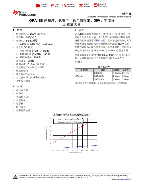
145125105856545255O f f s e t V o l t a g e (V )m -55-15525125Temperature (C)°-35456585105ProductFolder Order NowTechnical Documents Tools &SoftwareSupport &CommunityOPA188ZHCSB21B –MARCH 2013–REVISED SEPTEMBER 2016OPA188高精度、低噪声、轨至轨输出、36V 、零漂移运算放大器1特性•低失调电压:25μV (最大值)•零漂移:0.03μV/°C •低噪声:8.8nV/√Hz–0.1Hz 至10Hz 噪声:0.25μV PP •出色的DC 精度:–电源抑制比(PSRR);142dB –共模抑制比(CMRR):146dB –开环路增益:136dB •增益带宽:2MHz•静态电流:510μA (最大值)•宽电源电压:±2V 至±18V •轨至轨输出•输入包括负电源轨•已过滤射频干扰(RFI)的输入•微型尺寸封装2应用•桥式放大器•应力计•传感器应用•温度测量•电子称•医疗仪表•电阻温度检测器3说明OPA188运算放大器采用TI 的专有自动归零技术,以提供低失调电压(最大为25μV )并随时间推移和温度变化而实现接近零漂移的性能。
此高精度低静态电流微型放大器提供高输入阻抗和摆幅为电源轨15mV 之内的轨到轨输出。
输入共模范围包括负电源轨。
单电源或双电源可在4V 至36V (±2V 至±18V )范围内使用。
单通道版本采用微型SOT-23-5、MSOP-8和SO-8封装。
所有版本的额定工作温度范围均为-40°C 至+125°C 。
器件信息(1)器件型号封装封装尺寸(标称值)OPA188SOIC (8) 4.90mm x 3.91mm SOT-23(5) 2.90mm ×1.60mm VSSOP (8)3.00mm ×3.00mm(1)要了解所有可用封装,请参阅数据表末尾的封装选项附录。
艾登Moeller系列NZM模具电路保护器技术数据表说明书

Eaton 281299Eaton Moeller series NZM - Molded Case Circuit Breaker. Circuit-breaker, 3p, 20A, H2-M20General specificationsEaton Moeller series NZM molded casecircuit breaker thermo-magnetic281299149 mm184 mm105 mm2.345 kg RoHS conformIEC/EN 60947 IEC NZMH2-M20Product Name Catalog NumberProduct Length/Depth Product Height Product Width Product Weight Compliances Certifications Model Code20 AIs the panel builder's responsibility. The specifications for the switchgear must be observed.5 kA130 kAMeets the product standard's requirements.Is the panel builder's responsibility. The specifications for the switchgear must be observed.Built-in device fixed built-in techniqueFixed20 ADoes not apply, since the entire switchgear needs to be evaluated.Max. 10 segments of 24 mm x 0.8 mm at rear-side connection (punched)Max. 8 segments of 24 mm x 1 mm (2x) at box terminal Min. 2 segments of 9 mm x 0.8 mm at box terminalMin. 2 segements of 16 mm x 0.8 mm at rear-side connection (punched)Max. 10 segments of 16 mm x 0.8 mm at box terminalRocker leverMeets the product standard's requirements.40 °C eaton-circuit-breaker-let-through-current-nzm-mccb-characteristic-curve-005.epseaton-circuit-breaker-characteristic-power-defense-mccb-characteristic-curve-037.epsMH2-M20il01206006z2015_11.pdfVorstellung des neuen digitalen Leistungsschalter NZMDas neue digitale NZM-Sortiment - In Kurze verfugbar DEDA-CD-nzm2_3pDA-CS-nzm2_3peaton-manual-motor-starters-starter-msc-r-reversing-starter-wiring-diagram.epseaton-manual-motor-starters-starter-nzm-mccb-wiring-diagram.epseaton-nzm-technical-information-sheeteaton-circuit-breaker-nzm-mccb-dimensions-019.epsRated operational current for specified heat dissipation (In) 10.11 Short-circuit ratingRated short-circuit breaking capacity Ics (IEC/EN 60947) at 690 V, 50/60 HzRated short-circuit breaking capacity Icu (IEC/EN 60947) at 400/415 V, 50/60 Hz10.4 Clearances and creepage distances10.12 Electromagnetic compatibilityMounting MethodAmperage Rating10.2.5 LiftingTerminal capacity (copper strip)Handle type10.2.3.1 Verification of thermal stability of enclosuresAmbient storage temperature - min Characteristic curveeCAD model Installationsanleitung Installationsvideos mCAD modelSchaltpläneTechnische Datenblätter ZeichnungenFitted with:Thermal protectionProtection against direct contactFinger and back-of-hand proof to VDE 0106 part 100Terminal capacity (copper busbar)Max. 24 mm x 8 mm direct at switch rear-side connectionM8 at rear-side screw connectionMin. 16 mm x 5 mm direct at switch rear-side connection10.8 Connections for external conductorsIs the panel builder's responsibility.Special featuresMaximum back-up fuse, if the expected short-circuit currents at the installation location exceed the switching capacity of the circuit breaker (Rated short-circuit breaking capacity Icn) Rated current = rated uninterrupted current: 20 A Tripping class 10 A IEC/EN 60947-4-1, IEC/EN 60947-2 The circuit-breaker fulfills all requirements for AC-3 switching category.Ambient operating temperature - max70 °CClimatic proofingDamp heat, cyclic, to IEC 60068-2-30Damp heat, constant, to IEC 60068-2-78Terminal capacity (aluminum stranded conductor/cable)25 mm² - 50 mm² (1x) direct at switch rear-side connection25 mm² - 185 mm² (1x) at tunnel terminal25 mm² - 50 mm² (2x) direct at switch rear-side connectionTerminal capacity (copper stranded conductor/cable)25 mm² - 70 mm² (2x) direct at switch rear-side connection25 mm² - 185 mm² (1x) direct at switch rear-side connection25 mm² - 185 mm² (1x) at box terminal25 mm² - 70 mm² (2x) at box terminal25 mm² - 185 mm² (1x) at 1-hole tunnel terminalLifespan, electrical7500 operations at 690 V AC-15000 operations at 690 V AC-310000 operations at 415 V AC-16500 operations at 400 V AC-310000 operations at 400 V AC-16500 operations at 415 V AC-3Electrical connection type of main circuitScrew connectionShort-circuit total breaktime< 10 msRated impulse withstand voltage (Uimp) at main contacts8000 VRated short-circuit breaking capacity Ics (IEC/EN 60947) at 400/415 V, 50/60 Hz130 kA10.9.3 Impulse withstand voltageIs the panel builder's responsibility.Utilization categoryA (IEC/EN 60947-2)Number of polesThree-poleAmbient operating temperature - min-25 °C10.6 Incorporation of switching devices and componentsDoes not apply, since the entire switchgear needs to be evaluated.10.5 Protection against electric shockDoes not apply, since the entire switchgear needs to be evaluated.Terminal capacity (control cable)0.75 mm² - 1.5 mm² (2x)0.75 mm² - 2.5 mm² (1x)Equipment heat dissipation, current-dependent5.1 WInstantaneous current setting (Ii) - min350 A10.13 Mechanical functionThe device meets the requirements, provided the information in the instruction leaflet (IL) is observed.10.2.6 Mechanical impactDoes not apply, since the entire switchgear needs to be evaluated.10.9.4 Testing of enclosures made of insulating materialIs the panel builder's responsibility.Rated operational current16 A (400 V AC-3)Rated short-circuit breaking capacity Ics (IEC/EN 60947) at 230 V, 50/60 Hz150 kAApplicationUse in unearthed supply systems at 690 V10.3 Degree of protection of assembliesDoes not apply, since the entire switchgear needs to be evaluated.Rated short-circuit making capacity Icm at 240 V, 50/60 Hz330 kARated short-circuit breaking capacity Ics (IEC/EN 60947) at 440 V, 50/60 Hz130 kADegree of protection (IP), front sideIP40 (with insulating surround)IP66 (with door coupling rotary handle)Rated short-circuit making capacity Icm at 525 V, 50/60 Hz105 kARated short-circuit making capacity Icm at 690 V, 50/60 Hz40 kAInstantaneous current setting (Ii) - max350 AOverload current setting (Ir) - min16 A10.2.3.2 Verification of resistance of insulating materials to normal heatMeets the product standard's requirements.10.2.3.3 Resist. of insul. mat. to abnormal heat/fire by internal elect. effectsMeets the product standard's requirements.Lifespan, mechanical20000 operationsOverload current setting (Ir) - max20 AVoltage rating690 V - 690 VTerminal capacity (copper solid conductor/cable)6 mm² - 16 mm² (2x) at box terminal6 mm² - 16 mm² (2x) direct at switch rear-side connection16 mm² (1x) at tunnel terminal10 mm² - 16 mm² (1x) at box terminal10 mm² - 16 mm² (1x) direct at switch rear-side connectionDegree of protection (terminations)IP10 (tunnel terminal)IP00 (terminations, phase isolator and strip terminal)10.9.2 Power-frequency electric strengthIs the panel builder's responsibility.Short-circuit release non-delayed setting - min350 ADegree of protectionIP20 (basic degree of protection, in the operating controls area) IP20Overvoltage categoryIIIRated short-time withstand current (t = 1 s)1.9 kARated impulse withstand voltage (Uimp) at auxiliary contacts 6000 VTerminal capacity (aluminum solid conductor/cable)10 mm² - 16 mm² (2x) direct at switch rear-side connection10 mm² - 16 mm² (1x) direct at switch rear-side connection16 mm² (1x) at tunnel terminalSwitch off techniqueThermomagneticRated short-time withstand current (t = 0.3 s)1.9 kAAmbient storage temperature - max70 °CRated short-circuit breaking capacity Ics (IEC/EN 60947) at 525 V, 50/60 Hz37.5 kAOptional terminalsBox terminal. Connection on rear. Tunnel terminalRelease systemThermomagnetic releasePollution degree310.7 Internal electrical circuits and connectionsIs the panel builder's responsibility.Rated operating power at AC-3, 230 V5.5 kW10.10 Temperature riseThe panel builder is responsible for the temperature rise calculation. Eaton will provide heat dissipation data for the devices.FunctionsMotor protectionShort-circuit release non-delayed setting - max350 AStandard terminalsScrew terminalRated short-circuit making capacity Icm at 400/415 V, 50/60 Hz 330 kARated operating power at AC-3, 400 V7.5 kWTypeCircuit breaker10.2.2 Corrosion resistanceMeets the product standard's requirements.10.2.4 Resistance to ultra-violet (UV) radiationMeets the product standard's requirements.10.2.7 InscriptionsMeets the product standard's requirements.Rated short-circuit making capacity Icm at 440 V, 50/60 Hz 286 kAIsolation500 V AC (between auxiliary contacts and main contacts)300 V AC (between the auxiliary contacts)Number of operations per hour - max120Circuit breaker frame typeNZM2Direction of incoming supplyAs requiredShock resistance20 g (half-sinusoidal shock 20 ms)Eaton Konzern plc Eaton-Haus30 Pembroke-Straße Dublin 4, Irland © 2023 Eaton. Alle Rechte vorbehalten. Eaton ist eine eingetrageneMarke.Alle anderen Warenzeichen sindEigentum ihrer jeweiligenBesitzer./socialmedia1000 VRated insulation voltage (Ui)。
启英泰伦双麦离在线语音识别模组硬件规格书 CI-B03ST01S-BK说明书

双麦离在线语音识别模组硬件规格书型号:CI-B03ST01S-BK版本:V1.0文件历史跟踪DOCUMENT HISTORY PAGE版本号Rev.NO.发起者Originator描述Description日期Date V1.0启英泰伦新建文档2020/05/10声明本手册由成都启英泰伦科技有限公司版权所有,未经许可,任何单位和个人都不得以电子的、机械的、磁性的、光学的、化学的、手工的等形式复制、传播、转录和保存该出版物,或翻译成其他语言版本。
一经发现,将追究其法律责任。
启英泰伦保留更改本手册的权利,请在订购时联系我们以获得产品最新信息。
对任何用户使用我们产品时侵犯第三方版权或其他权利的行为本公司概不负责。
另外,在启英泰伦未明确表示产品有该项用途时,对于产品使用在极端条件下导致一些失灵或损毁而造成的损失概不负责。
目录1概述 (5)2模组主芯片描述 (7)3模组实物图 (10)4硬件接口定义 (12)5电路设计参考 (15)5.1电源 (15)5.2ADC接口 (15)5.3升级接口 (15)5.4PWM (15)5.5ESD设计 (15)5.6GPIO (16)5.7UART (16)5.8I2S音频接口 (16)5.9调试接口 (16)5.10DAC输出 (16)6电气参数 (17)7使用注意事项 (18)Chipintelli Technology Co.,Ltd.CONFIDENTIAL ALL RIGHTS RESERVED.This document is not to be reproduced,modified,adapted,published, translated in any material form in whole or in part nor disclosed to any third party without the prior writtenpermission of Chipintelli Technology Co.,Ltd.1概述启英泰伦双麦离在线语音识别模组CI-B03ST01S-BK是针对离在线应用开发的一款通用、便携、低功耗高性能语音识别模组,该模组具有以下功能和特点:⏹模组搭载高性能CI1103语音识别芯片,通过该芯片内置的基于深度神经网络(DNN)的硬件处理器,内置100条命令词离线语音识别功能,不依赖网络,时延小,且可保护用户隐私。
多点遗失辅助选择器:midastouch说明书

Package‘midastouch’October13,2022Type PackageVersion1.3Title Multiple Imputation by Distance Aided Donor SelectionDate2016-02-06Maintainer Philipp Gaffert<**********************>Depends R(>=3.2.0)Imports utilsSuggests miceDescription Contains the function mice.impute.midastouch().Technically this func-tion is to be run from within the'mice'package(van Buuren et al.2011),type??mice.It substi-tutes the method'pmm'within mice by'midastouch'.The authors have shown that'midas-touch'is superior to default'pmm'.Many ideas are based on Siddique/Belin2008's MIDAS. License GPL-2|GPL-3LazyLoad yesLazyData yesURL https://www.uni-bamberg.de/fileadmin/uni/fakultaeten/sowi_lehrstuehle/ statistik/Personen/Dateien_Florian/properPMM.pdfNeedsCompilation noAuthor Philipp Gaffert[aut,cre],Florian Meinfelder[aut],V olker Bosch[aut]Repository CRANDate/Publication2016-02-0709:35:46R topics documented:mice.impute.midastouch (2)Index51mice.impute.midastouchPredictive Mean Matching with distance aided selection of donorsDescriptionImputes univariate missing data using predictive mean matchingUsagemice.impute.midastouch(y,ry,x,ridge=1e-05,midas.kappa=NULL,outout=TRUE,neff=NULL,debug=NULL,...)Argumentsy Numeric vector with incomplete datary Response pattern of y(TRUE=observed,FALSE=missing)x Design matrix with length(y)rows and p columns containing complete covari-ates.ridge The ridge penalty applied to prevent problems with multicollinearity.The de-fault is ridge=1e-05,which means that0.001percent of the diagonal is addedto the rger ridges may result in more biased estimates.Forhighly noisy data(e.g.many junk variables),set ridge=1e-06or even lowerto reduce bias.For highly collinear data,set ridge=1e-04or higher.midas.kappa Scalar.If NULL(default)then the optimal kappa gets selected automatically.Alternatively,the user may specify a scalar.Siddique and Belin2008findmidas.kappa=3to be sensible.outout Logical.If TRUE(default)one model is estimated for each donor(leave-one-out principle).For speedup choose outout=FALSE,which estimates one modelfor all observations leading to in-sample predictions for the donors and out-of-sample predictions for the recipients.Mind the inappropriateness,though.neff FOR EXPERTS.Null or character string.The name of an existing environ-ment in which the effective sample size of the donors for each loop(CE it-erations times multiple imputations)is supposed to be written.The effectivesample size is necessary to compute the correction for the total variance as orig-inally suggested by Parzen,Lipsitz and Fitzmaurice2005.The objectname ismidastouch.neff.debug FOR EXPERTS.Null or character string.The name of an existing environmentin which the input is supposed to be written.The objectname is midastouch.inputlist....Other named arguments.DetailsImputation of y by predictive mean matching,based on Rubin(1987,p.168,formulas a and b)and Siddique and Belin2008.The procedure is as follows:1.Draw a bootstrap sample from the donor pool.2.Estimate a beta matrix on the bootstrap sample by the leave one out principle.pute type II predicted values for yobs(nobs x1)and ymis(nmis x nobs).4.Calculate the distance between all yobs and the corresponding ymis.5.Convert the distances in drawing probabilities.6.For each recipient draw a donor from the entire pool while considering the probabilities fromthe model.7.Take its observed value in y as the imputation.ValueNumeric vector of length sum(!ry)with imputationsAuthor(s)Philipp Gaffert,Florian Meinfelder,V olker Bosch2015ReferencesGaffert,P.,Meinfelder,F.,Bosch V.(2015)Towards an MI-proper Predictive Mean Matching,Dis-cussion Paper.https://www.uni-bamberg.de/fileadmin/uni/fakultaeten/sowi_lehrstuehle/ statistik/Personen/Dateien_Florian/properPMM.pdfLittle,R.J.A.(1988),Missing data adjustments in large surveys(with discussion),Journal of Busi-ness Economics and Statistics,6,287–301.Parzen,M.,Lipsitz,S.R.,Fitzmaurice,G.M.(2005),A note on reducing the bias of the approxi-mate bayesian bootstrap imputation variance estimator.Biometrika92,4,971–974.Rubin,D.B.(1987),Multiple imputation for nonresponse in surveys.New York:Wiley.Siddique,J.,Belin,T.R.(2008),Multiple imputation using an iterative hot-deck with distance-based donor selection.Statistics in medicine,27,1,83–102Van Buuren,S.,Brand,J.P.L.,Groothuis-Oudshoorn C.G.M.,Rubin,D.B.(2006),Fully conditional specification in multivariate imputation.Journal of Statistical Computation and Simulation,76,12, 1049–1064.Van Buuren,S.,Groothuis-Oudshoorn,K.(2011),mice:Multivariate Imputation by Chained Equa-tions in R.Journal of Statistical Software,45,3,1–67./v45/i03/ Examples##from R::mice,slightly adapted###do default multiple imputation on a numeric matrixlibrary(midastouch)library(mice)imp<-mice(nhanes,method= midastouch )imp#list the actual imputations for BMIimp$imp$bmi#first completed data matrixcomplete(imp)#imputation on mixed data with a different method per column mice(nhanes2,method=c( sample , midastouch , logreg , norm ))Index∗micemice.impute.midastouch,2mice.impute.midastouch,2midastouch(mice.impute.midastouch),25。
半导体传感器AD7323BRUZ中文规格书

Data SheetADuM1400/ADuM1401/ADuM1402 Rev. L | Page 21 of 31ABSOLUTE MAXIMUM RATINGSAmbient temperature = 25°C, unless otherwise noted. Table 13.ParameterRating Storage Temperature (T ST )−65°C to +150°C Ambient Operating Temperature (T A )1−40°C to +105°C Ambient Operating Temperature (T A )2−40°C to +125°C Supply Voltages (V DD1, V DD2)3−0.5 V to +7.0 V Input Voltage (V IA , V IB , V IC , V ID , V E1, V E2)3, 4−0.5 V to V DDI + 0.5 V Output Voltage (V OA , V OB , V OC , V OD )3, 4−0.5 V to V DDO + 0.5 V Average Output Current per Pin 5Side 1 (I O1)−18 mA to +18 mA Side 2 (I O2)−22 mA to +22 mA Common-Mode Transients 6−100 kV/µs to +100 kV/µs 1 Does not apply to ADuM1400W , ADuM1401W , and ADuM1402W automotive grade versions.2 Applies to ADuM1400W , ADuM1401W , and ADuM1402W automotive grade versions.3 All voltages are relative to their respective ground.4 V DDI and V DDO refer to the supply voltages on the input and output sides of a given channel, respectively. See the PC Board Layout section.5 See Figure 4 for maximum rated current values for various temperatures.6 This refers to common-mode transients across the insulation barrier. Common-mode transients exceeding the Absolute Maximum Ratings may cause latch-up or permanent damage.Stresses at or above those listed under Absolute Maximum Ratings may cause permanent damage to the product. This is a stress rating only; functional operation of the product at these or any other conditions above those indicated in the operational section of this specification is not implied. Operation beyond the maximum operating conditions for extended periods may affect product reliability. ESD CAUTION Table 14. Maximum Continuous Working Voltage 1ParameterMax Unit Constraint AC Voltage, Bipolar Waveform565 V peak 50-year minimum lifetime AC Voltage, Unipolar WaveformBasic Insulation1131 V peak Maximum approved working voltage per IEC 60950-1 Reinforced Insulation560 V peak Maximum approved working voltage per IEC 60950-1 and VDE V 0884-10 DC VoltageBasic Insulation1131 V peak Maximum approved working voltage per IEC 60950-1 Reinforced Insulation560 V peak Maximum approved working voltage per IEC 60950-1 and VDE V 0884-10 1 Refers to continuous voltage magnitude imposed across the isolation barrier. See the Insulation Lifetime section for more details. Table 15. Truth Table (Positive Logic)V Ix Input 1V Ex Input 1, 2 V DDI State 1 V DDO State 1 V Ox Output 1 Notes HH or NC Powered Powered H LH or NC Powered Powered L XL Powered Powered Z XH or NC Unpowered Powered H Outputs return to the input state within 1 µs of V DDI power restoration. XL Unpowered Powered Z X X Powered Unpowered Indeterminate Outputs return to the input state within 1 µs of V DDO power restoration if the V Ex state is H or NC. Outputs return to a high impedance statewithin 8 ns of V DDO power restoration if the V Ex state is L.1V Ix and V Ox refer to the input and output signals of a given channel (A, B, C, or D). V Ex refers to the output enable signal on the same side as the V Ox outputs. V DDI and V DDO refer to the supply voltages on the input and output sides of the given channel, respectively.2 In noisy environments, connecting V Ex to an external logic high or low is recommended.ADuM1400/ADuM1401/ADuM1402 Data SheetRev. L | Page 30 of 31OUTLINE DIMENSIONSCONTROLLING DIMENSIONS ARE IN MILLIMETERS;INCH DIMENSIONS (IN PARENTHESES)ARE ROUNDED-OFF MILLIMETER EQUIVALENTS FOR REFERENCE ONLY AND ARE NOT APPROPRIATE FOR USE IN PLIANT TO JEDEC STANDARDS MS-013-AA03-27-2007-B Figure 24. 16-Lead Standard Small Outline Package [SOIC_W] Wide Body (RW-16) Dimensions shown in millimeters and (inches) ORDERING GUIDEModel1, 2, 3, 4Number of Inputs, V DD1 Side Number of Inputs, V DD2 Side Maximum Data Rate (Mbps) Maximum Propagation Delay, 5 V (ns) Maximum Pulse Width Distortion (ns) Temperature Range Package Description Package Option ADuM1400ARW4 0 1 100 40 −40°C to +105°C 16-Lead SOIC_W RW-16 ADuM1400BRW4 0 10 50 3 −40°C to +105°C 16-Lead SOIC_W RW-16 ADuM1400CRW4 0 90 32 2 −40°C to +105°C 16-Lead SOIC_W RW-16 ADuM1400ARWZ4 0 1 100 40 −40°C to +105°C 16-Lead SOIC_W RW-16 ADuM1400BRWZ4 0 10 50 3 −40°C to +105°C 16-Lead SOIC_W RW-16 ADuM1400CRWZ4 0 90 32 2 −40°C to +105°C 16-Lead SOIC_W RW-16 ADuM1400WSRWZ4 0 1 100 40 −40°C to +125°C 16-Lead SOIC_W RW-16 ADuM1400WTRWZ4 0 10 34 3 −40°C to +125°C 16-Lead SOIC_W RW-16 ADuM1401ARW3 1 1 100 40 −40°C to +105°C 16-Lead SOIC_W RW-16 ADuM1401BRW3 1 10 50 3 −40°C to +105°C 16-Lead SOIC_W RW-16 ADuM1401CRW3 1 90 32 2 −40°C to +105°C 16-Lead SOIC_W RW-16 ADuM1401ARWZ3 1 1 100 40 −40°C to +105°C 16-Lead SOIC_W RW-16 ADuM1401BRWZ3 1 10 50 3 −40°C to +105°C 16-Lead SOIC_W RW-16 ADuM1401CRWZ3 1 90 32 2 −40°C to +105°C 16-Lead SOIC_W RW-16 ADuM1401WSRWZ3 1 1 100 40 −40°C to +125°C 16-Lead SOIC_W RW-16 ADuM1401WTRWZ3 1 10 34 3 −40°C to +125°C 16-Lead SOIC_W RW-16 ADuM1402ARW2 2 1 100 40 −40°C to +105°C 16-Lead SOIC_W RW-16 ADuM1402BRW2 2 10 503 −40°C to +105°C 16-Lead SOIC_W RW-16 ADuM1402CRW2 2 90 32 2 −40°C to +105°C 16-Lead SOIC_W RW-16 ADuM1402ARWZ2 2 1 100 40 −40°C to +105°C 16-Lead SOIC_W RW-16 ADuM1402BRWZ2 2 10 503 −40°C to +105°C 16-Lead SOIC_W RW-16 ADuM1402CRWZ2 2 90 32 2 −40°C to +105°C 16-Lead SOIC_W RW-16 ADuM1402WSRWZ2 2 1 100 40 −40°C to +125°C 16-Lead SOIC_W RW-16 ADuM1402WTRWZ2 2 10 343 −40°C to +125°C 16-Lead SOIC_W RW-16 EVAL-ADuMQSEBZ Evaluation Board 1Z = RoHS Compliant Part. 2 W = Qualified for Automotive Applications. 3 Tape and reel are available. The addition of an -RL suffix designates a 13” (1,000 units) tape and reel option. 4 No tape and reel option is available for the ADuM1400CRW or ADuM1402BRW models.。
敦泰触摸IC参数对照表
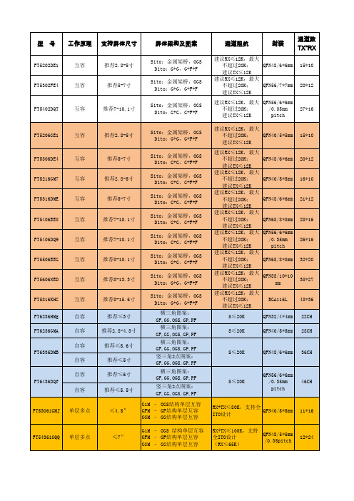
20*12
FT5402DQT
互容
推荐7-10.1寸
27*16
FT5206GE1
互容
推荐2.8-5寸
Sito:金属架桥,OGS Dito:G+G,G+F+F Sito:金属架桥,OGS Dito:G+G,G+F+F Sito:金属架桥,OGS Dito:G+G,G+F+F Sito:金属架桥,OGS Dito:G+G,G+F+F Sito:金属架桥,OGS Dito:G+G,G+F+F Sito:金属架桥,OGS Dito:G+G,G+F+F Sito:金属架桥,OGS Dito:G+G,G+F+F Sito:金属架桥,OGS Dito:G+G,G+F+F Sito:金属架桥,OGS Dito:G+G,G+F+F 横三角图案: GF,GG,OGS,GP,PF 横三角图案: GF,GG,OGS,GP,PF 横三角图案: GF,GG,OGS,GP,PF 竖三角2点图案: GF,GG,OGS,GP,PF 横三角图案: GF,GG,OGS,GP,PF 竖三角2点图案: GF,GG,OGS,GP,PF G1M – OGS结构单层互容 GFM – GF结构单层互容 GGM – GG结构单层互容 G1M – OGS 结构单层互容 GFM – GF结构单层互容 GGM – GG结构单层互容
工作电流:6mA 待机电流:4mA 睡眠电流:30uA
工作温度: -20~+85 储存温度: -55~+150 工作温度: -20~+85 储存温度: -55~+150
北欧轨道 NTC59021 产品使用指南说明书

USER'S MANUALCAUTIONRead all precautions and instruc-tions in this manual before using this equipment. Keep this manual for future reference.Serial Number DecalQUESTIONS?As a manufacturer, we are com-mitted to providing complete customer satisfaction. If you have questions, or if there are missing parts, we will guarantee satisfaction through direct assis-tance from our factory.TO AVOID DELAYS, PLEASE CALL DIRECT TO OUR TOLL-FREE CUSTOMER HOT LINE.The trained technicians on our customer hot line will provide immediate assistance, free of charge to you.CUSTOMER HOT LINE:1-888-825-2588Mon.–Fri., 6 a.m.–6 p.m. MSTModel No. NTC59021Serial No.Visit our website at new products, prizes,fitness tips, and much more!Patent PendingNordicTrack is a registered trademark of ICON Health & Fitness, Inc.Congratulations for selecting the new NordicTrack®SL700exercise cycle. Cycling is one of the most effective exercises for increasing cardiovascular fit-ness, building endurance, and toning the entire body. The NordicTrack®SL700 offers an impressive array of features designed to let you enjoy this healthful exercise in the comfort and privacy of your home. For your benefit, read this manual carefully before you use the exercise cycle.If you have questions after reading this manual, call our Customer Service Department toll-free at 1-888-825-2588, Monday through Friday, 6 a.m. until 6 p.m. Mountain Time (excluding holidays). To help us assist you, mention the product model number and serial number when calling. The model number is NTC59021. The serial number can be found on a decal attached to the exer-cise cycle (see the front cover of this manual for the location of the decal).Before reading further, please familiarize yourself with the parts that are labeled in the drawing below.FEATURES OF THE CONSOLEThe advanced console offers a selection of features designed to make your workouts more enjoyable and effective. When the manual mode of the console is selected, the resistance of the exercise cycle can be changed with a touch of a button. As you exercise, the console will provide continuous exercise feedback. You can even measure your heart rate using the hand-grip pulse sensor. Note: For information about an optional chest pulse sensor, see page 19.The console also offers six resistance and pace pro-grams. Each program automatically changes the resis-tance of the exercise cycle and prompts you to increase or decrease your pace as it guides you through an effective workout.In addition, the console features two heart rate pro-grams that automatically change the resistance of the exercise cycle and prompt you to vary your pace to keep your heart rate near a target heart rate as you exercise.The console also features new interactive technology. Having technology is like having a personal trainer in your home. Using the included audio cable, you can connect the exercise cycle to your home stereo, portable stereo, or computer and play special CD programs (CD’s are available sep-arately). CD programs automatically control the resistance of the exercise cycle and prompt you to vary your pace as a personal trainer coaches you through every step of your workout. High-energy music provides added motivation. Each CD features two pro-grams designed by certified personal trainers.In addition, you can connect the exercise cycle to your VCR and TV and play video programs (video-cassettes are available separately).Video programs offer the same benefits as CD programs, and add the excitement of working out with a class and an instructor.With the exercise cycle connected to your computer, you can also go to our Web site at and access programs directly from the internet. Explore for details.To purchase CD’s and videocassettes, call toll-free 1-800-735-0768.HOW TO CONNECT YOUR CD PLAYER, VCR,OR COMPUTERTo use CD’s , the exercise cycle must be connected to your portable CD player, portable stereo,home stereo, or computer with CD player. See pages 15 and 16 for connecting instructions. To use videocassettes , the exercise cycle must be connected to your VCR. See page 17 for connecting instructions.To use programs directly from our Web site , the exercise cycle must be connected to your home computer. See page 16 for connecting instruc-tions.HOW TO CONNECT YOUR PORTABLE CD PLAYER Note: If your CD player has separate LINE OUT and PHONES jacks, see instruction A below. If your CD player has only one jack, see instruction B.A.Plug one end of the audio cable into the jack beneath the console. Plug the other end of the cable into the LINE OUT jack on your CD player.Plug your headphones into the PHONES jack.B.Plug one end of the audio cable into the jack beneath the console. Plug the other end of the cable into a 1/8” Y-adapter (available at electronics stores). Plug the Y-adapter into the PHONES jack on your CD player. Plug your headphones into the other side of the Y-adapter.HOW TO CONNECT YOUR PORTABLE STEREO Note: If your stereo has an RCA-type AUDIO OUT jack, see instruction A below. If your stereo has a 1/8” LINE OUT jack, see instruction B. If yourstereo has only a PHONES jack, see instruction C.A.Plug one end of the audio cable into the jackbeneath the console. Plug the other end of the cable into the adapter. Plug the adapter into an AUDIO OUT jack on your stereo.B.Plug one end of the audio cable into the jack beneath the console. Plug the other end of the cable into the LINE OUT jack on your stereo. Do not use the adapter.C.Plug one end of the audio cable into the jack beneath the console. Plug the other end of the cable into a 1/8” Y-adapter (available at electronics stores). Plug the Y-adapter into the PHONES jack on your stereo. Plug your headphones into the other side of the Y-adapter.HOW TO CONNECT YOUR HOME STEREONote: If your stereo has an unused LINE OUT jack, see instruction A below. If the LINE OUT jack is being used, see instruction B.A.Plug one end of the audio cable into the jackbeneath the console. Plug the other end of thecable into the adapter. Plug the adapter into theLINE OUT jack on your stereo.B.Plug one end of the audio cable into the jackbeneath the console. Plug the other end of thecable into the adapter. Plug the adapter into anRCA Y-adapter (available at electronics stores).Next, remove the wire that is currently plugged into the LINE OUT jack on your stereo and plug thewire into the unused side of the Y-adapter. Plug the Y-adapter into the LINE OUT jack on your stereo. HOW TO CONNECT YOUR COMPUTERNote: If your computer has a 1/8” LINE OUT jack, see instruction A. If your computer has only a PHONES jack, see instruction B.A.Plug one end of the audio cable into the jackbeneath the console. Plug the other end of thecable into the LINE OUT jack on your computer. B.Plug one end of the audio cable into the jackbeneath the console. Plug the other end of thecable into a 1/8” Y-adapter (available at electronics stores). Plug the Y-adapter into the PHONES jack on your computer. Plug your headphones or speak-ers into the other side of the Y-adapter.HOW TO USE PROGRAMS DIRECTLY FROM OUR WEB SITEOur Web site at allows you to play audio and video programs directly from the internet. To use programs from our Web site, the exer-cise cycle must be connected to your home computer.See HOW TO CONNECT YOUR COMPUTER on page 16. In addition, you must have an internet con-nection and an internet service provider. A list of spe-cific system requirements will be found on our Web site.Follow the steps below to use a program from our Web site.Go to your computer and start an internet connection.Start your Web browser, if necessary, and go to our Web site at .Follow the desired links on our Web site to select a program.Read and follow the on-line instructions for using a program.Follow the on-line instructions to start the program.When you start the program, an on-screen count-down will begin.Return to the exercise cycle and begin pedaling.When the on-screen countdown ends, the pro-gram will begin. The program will function in almost the same way as a resistance and pace program (see step 3 on page 12). However, an electronic “chirping” sound will alert you when the resistance setting and/or the pace setting is about to change.Monitor your progress with the two displays.See step 4 on page 10.Measure your heart rate if desired.hands-free 98765431 1 Frame2 1 Upright3 1 Handlebar4 1 Console5 1 Handlebar Cover6 2 Pulse Sensor7 1 Seat Bracket8 1Seat Post9 1 Seat10 1 Seat Knob 11 1 Seat Carriage 12 2 Seat Bushing 13 1 Front Stabilizer Cover 14 1 Rear Stabilizer Cover 15 1Front Stabilizer 16 1 Rear Stabilizer 17 2 Wheel 18 1 Right Pedal Strap 19 4 Leveling Foot 20 1 Seat Post Knob 21 1 Right Pedal 22 1 Left Pedal 23 1 Right Crank Arm 24 1 Left Crank Arm 25 1 Left Pedal Strap 26 1 Left Side Shield 27 1 Right Side Shield 28 1 Snap Ring 29 1 Pulley 30 1 Magnet31 1 Crank Assembly 32 1 Thrust Washer 33 2 Crank Bearing34 1 Flywheel/Generator 35 1 “C” Magnet36 1 Resistance Cable 37 1 Spring38 1 Resistance Motor39 1 Idler Arm40 1 Control Board 41 1 Control Bracket 42 1 Upper Wire Harness 43 1 Lower Wire Harness 44 1 Adjustment Bracket 45 1 Clamp46 1 Reed Switch/Wire 47 1 Drive Belt48 1 Flywheel Axle 49 1 Shoulder Screw 50 2 Flange Screw 514Stand-off 52 1 M10 Nylon Locknut 53 2 Bolt Set 54 12 M8 x 40mm Button Screw 55 18 M8 Split Washer 56 8 M4 x 38mm Screw 57 12 M4 x 16mm Screw 58 3 5/16” x 12mm Button Screw 59 4 M8 x 25mm Patch Screw 60 4 M5 x 12mm Screw 61 2Handgrip 62 1 M10 Washer 63 7 M8 Nylon Locknut 64 3 M6 Nut 65 13 M4 x 25mm Screw 66 1 Eyebolt 67 1 Idler Bolt 68 1 M10 x 22mm Tapered Bolt 692M5 Nut 701M6 x 38mm Bolt 714M5 Washer 724M6 Nylon Locknut 734M6 x 18mm Bolt # 1 Allen Wrench # 1 User’s ManualNote: “#” indicates a non-illustrated part. Specifications are subject to change without notice. See the back coverof this manual for information about ordering replacement parts.Key No.Qty.DescriptionKey No.Qty.DescriptionPART LIST—Model No. NTC59021R0503AEXPLODED DRAWING—Model No. NTC59021R0503APart No. 195806 R0503A Printed in China ©2003 ICON Health & Fitness, Inc.。
Monolithic Power eMotion System 智能电机模块评估套件 EVKT-MS

EVKT-MSM942038-24EVKT-MSM942038-24eMotion System TM Smart Motor ModuleEvaluation KitEvaluation Kit EVKT-MSM942038-24 ContentsPart Number EVKT-MSM942038-24Diameter (mm) 42 Power (W)38 Typical Voltage (V)24 InterfaceRS485# Part Number Item Quantity 1EVKT-MSM942038-24 BLDC motor withMMP742038-24 smart motor module installed 1 2eMotion System TMcommunication kitUSB communication interface with cable1FEATURESThe EVKT-MSM942038-24 evaluation kit is part of a family of fully integrated smart motor solutions for servo motor applications. This 42mm (NEMA 17), 38W motor integrates a brushless DC motor and a smart motor module. The user can program the system to operate in speed control mode, position control mode, or torque control mode. Two control interface options are available: an RS485 interface and a PULSE/DIR interface. Easy-to-use GUI software provides flexibility by allowing users to optimize the design online through the RS485 control interface. The parameters are saved in the motor module ’s non-volatile memory. A design guide for the GUI is available for download at .The smart motor modules can be ordered separately for customization into different motor types. The MMP742038-24 is the driver module part number used in the kit.The datasheet for the MMP742038-24 is available for download at .∙ 18V to 36V Input Voltage Range ∙ Max 38W Continuous Power Output ∙ 0.12N-m Rated Torque (0.36N-m Peak Torque)∙0.3° Position Resolution ∙ RS485 Interface and PULSE/DIR Interface ∙ Position, Speed, and Torque Control Modes ∙ Operating Temperature: 0°C to 70°C (Power Derated > 40°C) ∙ Storage Temperature: -40°C to +125°CORDERING INFORMATIONDESCRIPTIONEVKT-MSM942038-24 – eMOTION SYSTEM TM EVALUATION KITSmart Motor Module Evaluation KitParameter Condition Value UnitsInput voltage24 VOutput power0°C to40°C38 WPositionresolution0.3 °Nominal speed3000 rpmNominal torque0.12 N-mRotor inertia24 g-cm2Diameter42 mmShaft diameter 5 mmLength Body only 40 mmWeight300 gHARDWARE CONNECTIONSRECOMMENDED OPERATING CONDITIONSInput voltage ................................. 18V to 36VControl interface voltage ................ 0V to 5.5VMax pulse frequency .......................... 500kHzRS485 A/B voltage ........................ 0V to 5.5VRS485 common mode voltage ................±15VOperation temperature................. 0°C to 70°CStorage temperature ............. -40°C to +125°C EVALUATION KIT SPECIFICATIONSEVKT-MSM942038-24 – eMOTION SYSTEM TM EVALUATION KIT8 9 10 11 121 2 3 45 6 7Fault IndicationPower On IndicationT A = 25°C, V IN = 24V, unless otherwise noted.Pin NumberDesignation Pin Description RS485 Interface 1 EXT_5V5V input for firmware programming 2 B RS485 node B 3 AGND RS485 ground 4 A RS485 node A Power Interface5 GND Power ground6 R- Shunt resistor return node7 VIN Input power supply Control Interface8 COM- Common return 9 EN+ Enable input 10 PEND+ Position end output11 PUL+ Pulse input 12DIR+Direction inputPIN CONFIGURATIONTYPICAL PERFORMANCE CHARACTERISTICSEVKT-MSM942038-24 – eMOTION SYSTEM TM EVALUATION KITMECHANICAL DRAWINGEVKT-MSM942038-24。
- 1、下载文档前请自行甄别文档内容的完整性,平台不提供额外的编辑、内容补充、找答案等附加服务。
- 2、"仅部分预览"的文档,不可在线预览部分如存在完整性等问题,可反馈申请退款(可完整预览的文档不适用该条件!)。
- 3、如文档侵犯您的权益,请联系客服反馈,我们会尽快为您处理(人工客服工作时间:9:00-18:30)。
Please read Cautions and warnings and Important notes at the end of this document.
Page 5 of 24
Options Alternative resistance ratings, resistance tolerances and B value tolerances available on request.
Delivery mode Cardboard tape, 180-mm reel
Dimensional drawing
NTC thermistors for temperature measurement
SMD NTC thermistors, case size 0603 (1608), automotive series
Series/Type: Date:
B573**V5 June 2012
© EPCOS AG 2012. Reproduction, publication and dissemination of this publication, enclosures hereto and the information contained therein without EPCOS' prior express consent is prohibited.
Biased humidity
Operational life
External visual Physical dimensions Resistance to solvents Mechanical shock
Standard
Test conditions Resistance at: 25 °C and 100 °C
Features Qualification based on AEC-Q200 Rev-D Multilayer SMD NTC with inner electrodes Nickel barrier termination For temperature measurement up to 150 °C Excellent long-term aging stability in high temperature and high humidity environment
UL-94, V-0 or V-1
Not applicable for SMD thermistors (component is not coated or
encapsulated with plastic materials)
AEC-Q200-005, Max. bending: 2 mm
method -005 Duration @ max. bending: 60 s
8500 8502 8507 8509 8509 8502 8507 8507 8507 8507 8507
B25/50 K
3590 3940 4386 3380 3380 3940 4386 4386 4386 4386 4386
B25/85 K
3635 3980 4455 3435 3435 3980 4455 4455 4455 4455 4455
B25/100
K
3650 ±3% 4000 ±3% 4480 ±3% 3455 ±1% 3455 ±1% 4000 ±3% 4480 ±3% 4480 ±3% 4480 ±1% 4480 ±1% 4480 ±3%
Ordering code
B57342V5103+060 B57351V5103+060 B57352V5103+060 B57332V5103+360 B57332V5103F360 B57351V5223+060 B57352V5223+060 B57352V5473+060 B57352V5104+360 B57352V5104F360 B57352V5104+060
Dimensions in mm Approx. weight 6 mg
General technical data
Operating temperature range Max. power Resistance tolerance Rated temperature Dissipation factor Thermal cooling time constant Heat capacity
Test temperature: 150 °C Pmax = 0.35 mW Duration: 1000 h
MIL-STD-883E, Visual inspection
method 2009
JESD22,
Measured with calibers
method JB-100
< 3% < 3%
MIL-STD-202, method 215
1) Depends on mounting situation
Please read Cautions and warnings and Important notes at the end of this document.
Page 2 of 24
Temperature measurement and compensation SMD NTC thermistors, case size 0603 (1608)
J-STD-002
a) Dip: 235 °C; 5 s: aging 4 h @ 155 °C b) Dip: 215 °C; 5 s: steam aging 8 h @ 92 °C c) Dip: 260 °C; 7 s: steam aging 8 h @ 92 °C
R(25 °C), R(100 °C), B(25/100)
+ = Resistance tolerance
F = ±1% (only for type B57332V5103F360 and B57352V5104F360) H = ±3% J = ±5%
Please read Cautions and warnings and Important notes at the end of this document.
AEC-Q200-006, Max. F: 10 N method -006
Reflow soldering profile
Wave soldering profile
∆R25/R25 Remarks (typical) < 1%
< 1% < 3%
95% of termination wetted
in the specified values
Temperature cycling is performed acc. MIL-STD-202, method 107. No warrant will be assumed for the reliability of solder joint.
Within the specified values
B573**V5 Automotive series
Test Vibration
Resistance to soldering heat ESD
Solderability
Electrical characterization Flammability
Board flex Terminal strength Resistance drift after soldering
∆R25/R25 Remarks (typical)
MIL-STD-202, method 108
JESD22, method JA-104
Test temperature: 150 °C Duration: 1000 h Unpowered
Lower test temperature: 40 °C Upper test temperature: 150 °C Number of cycles: 1000 Transfer time: < 10 s Dwell time: 15 min Air Air
method 210 1 heat cycle
AEC-Q200-002, Discharge capacitance: 150 pF method -002 Discharge resistance: 2 kΩ
Charging voltage: 6 kV
Contact discharge
2 pulses in each polarity
Temperature measurement and compensation SMD NTC thermistors, case size 0603 (1608)
B573**V5 Automotive series
Applications Temperature measurement and compensation
(at 25 °C, on PCB)
(on PCB) (on PCB)
Top P251) ∆RR/RR TR δth1) τc1) Cth1)
40 ... 150 180 ±1, ±3, ±5 25 approx. 3 approx. 4 approx. 12
°C mW % °C mW/K s mJ/K
Please read Cautions and warnings and Important notes at the end of this document.
Page 4 of 24
Temperature measurement and compensation SMD NTC thermistors, case size 0603 (1608)