PBSS5250X,115;PBSS5250X,135;中文规格书,Datasheet资料
CommScope HT3540H Series双密度全谱宽带WDM传输系统商品说明书

DATA SHEETHeadend Optics Platform (CH3000)HT3540H SeriesDouble-Density Full Spectrum DWDM Transmitter SystemThe CommScope HT3540H Series Double ‐Density Full Spectrum Dense Wave Division Multiplexing (DWDM) Transmitter System provides high performance and a high rack density forward path transmission solution for Cable TV service providers.The high ‐density packaging design allows up to four (4) HT3540H series high performance transmitters plus a CC3008 Communications Control Module to be stacked vertically and contained by the CA3008 module carrier, requiring only two chassis slots of a 3RU chassis. The compact solution supports up to 24 transmitters in a CH3000 chassis, including redundant power supplies.•Available in 40 wavelengths on ITU 100 GHz grid •Hot plug ‐in/out, individually replaceable transmitter modules•Optimized for full spectrum loading•Analog loading up to 552 MHz plus QAM loading •Manual or Automatic Gain Control (AGC) modes •Low power consumption•High rack density: 24 transmitters per 3RU chassis, with redundant power supplies and optical multiplexing•Front panel ‐20 dB input test point •Front panel laser On/Off switch•Local and remote status monitoring featuresFEATURESWhen installed in the chassis, the transmitters interface to a “zero ‐slot” back plate, providing support for up to four HT3540H series transmitters. The figure below shows a fully loaded carrier mated to the BD35M4 Double ‐Density multiplexing back plate that supports optical combining of four DWDM wavelengths in the forward path.The CC3008 Communications Module installed at the top of a HT3540H series transmitter stack provides the communications interface between the transmitters and the CH3000 mid ‐plane bus, allowing complete configuration and management control of the stack, both local andremote.HT3540H Series Quad ‐Stack and CC3008 Communications Module joined with a BD35M4 Multiplexing Back PlateHT3540H Series Double Density Full Spectrum DWDM Transmitters (1.2 GHz Passband)CommScope HT3540H Series Double‐Density Full Spectrum DWDM Transmitters are a key element of the CommScope HFC and Fiber Deep architectures in support of the evolution to all QAM transmission. These high‐performance transmitters are designed for Dense Wave Division Multiplexing (DWDM) applications for point‐to‐point forward path transmission of full spectrum broadcast and narrowcast services.HT3541H series transmitters are designed for “light” analog channel loading from 0 to 30 analog channels (up to 258 MHz) plus QAM channel loading, or for all QAM loading. They are also designed for QAM‐only loading for digital services as part of a BC/NC overlay system.HT3542H series transmitters are designed for “full” analog channel loading from 0 to 79 analog channels (up to 552 MHz) plus QAM channel loading.HT3543H series transmitters are designed for all QAM loading.These transmitters incorporate advanced dispersion compensation circuitry to enable transmission of high‐quality signals over maximum distances.The above figure shows a front view of the CA3008 carrier components: a single HT354xH Double‐Density Transmitter (left); a single CC3008 Communications Module (right), and a fully loaded “stack” (center) providing four (4) DWDM transmitters, requiring only 2 vertical slots of a CH3000 Chassis. A fully loaded CH3000 chassis supports 24 Double‐Density DWDM transmitters and redundant power supplies.Features•DWDM transmitter: 40 wavelengths on the ITU grid •Manual or Automatic Gain Control (AGC) modes •RF input amplification up to +6 dB•Optimized for full spectrum loading•HT3541H: Analog loading up to 258 MHz plus QAM loading, or all QAM loading.•HT3542H: Analog loading up to 552 MHz, plus QAM loading•HT3543H: All QAM loading •Hot plug‐in/out, individually insertable•Low power consumption•Industry’s highest DWDM rack density: 24 transmitters per 3RU chassis, with redundant power supplies •Front access ‐20 dB input test point•Front panel laser On/Off interlock switch•Local and remote status monitoringHT3540H SERIES SPECIFICATIONSPhysicalDimensions11.5” D x 0.8” H x 2.0” W (29.2 x 2.0 x 5.1 cm)*Weight0.75 lbs. (0.34 kg)* Four (4) transmitter units designed to be vertically stacked, plus a CC3008 Communications Module, and installedinside a CA3008 Module Carrier. The combination occupies two slots in a 3RU CH3000 Chassis.EnvironmentalOperating‐20°to +65°C (‐4°to 149°F)Storage‐40°to +85°C (‐40°to +185°F)Humidity5% to 95% non‐condensingRF and Optical InterfaceRF Input F‐type male located on BD31A4 or BD35M4 Back PlatesInput RF Test Point G‐type male (located at front panel, ‐20 dB)Optical Connector SC/APC located on BD31A4 or BD35M4 Back PlatesPower RequirementsInput Voltage12 V DCPower Consumption10 W (per transmitter) including controller and back plate cooling fanGeneralHot plug‐in/outManual gain alignmentChannel LoadingHT3541H: 0–30 Analog channels (up to 258 MHz), plus QAM channelsHT3542H: 0–79 Analog channels (up to 552 MHz), plus QAM channelsHT3543H: All QAM channelsOpticalOptical Output Power10 ±0.25 dBmWavelength See DWDM ITU Channel Plans descriptionFiber Length HT3541H and HT3543H: 60 km max. (Dispersion Compensation adjustable in 5 km steps)HT3542H: 40 km max. (Dispersion Compensation adjustable in 1 km steps)Compatible with external dispersion compensation for some applicationsElectricalPassband45 to 1218 MHzFrequency Response (Flatness including Slope)•±1.0 dB (BC input @ 25°C)•±0.5 dB (NC input relative to BC input)Nominal RF Input Levels (Input Attenuator = 0 dB)HT3541H:•16.2 dBmV/ch for 30 analog channels into BC input•10.2 dBmV/ch for 256‐QAM channels into BC input, or 16.2 dBmv/ch into NC inputHT3542H:•15 dBmV/ch for 79 analog channels into BC input•9 dBmV/ch for 256‐QAM channels into BC input, or 15 dBmv/ch into NC inputHT3543H:•10.7 dBmV/ch for 154 256‐QAM channels into BC input, or 16.7 dBmV/ch into NC inputRF Input Impedance75 Ω, nomRF Input Return Loss18 dB, minRF Input Attenuator/Amplify Range (Manual Mode)‐6.0 to +5.0 dB Normal mode. High‐gain mode (+5.5, +6.0 dB) supports BC RF input port, NC RF input is terminated. RF Input Attenuator Step Size0.5 dBAGC Mode Maintains RF level to within ±3 dB of the learned RF valueLevel Stability (Typical)±0.5 dB (‐1 worst case relative to 25°C)256‐QAM BER< 10–5(pre‐FEC, ITU‐C)MER> 37 dB to 50°C; > 36 dB to 65°CLink Performance HT3541H HT3542H HT3543HLoading30A + 124 QAM79A + 75 QAM154 QAMLength (km)406030404060CNR* (dB):52505150See MER See MERCSO (dB):61586058‐‐CTB (dB):65656565‐‐* max 1 dB degradation at temperature extremesAn HT3541H transmitter can also be used as a narrowcast transmitter. For example, in BC/NC overlay systems, itwould have the performance of an AT3535G‐xx‐1‐AS transmitter.For more information about BC/NC overlay systemperformance and evolution from low NC 256‐QAM channel loading to full spectrum 256‐QAM channel loading, or forinformation about full spectrum multiwavelength applications with up to 40 DWDM wavelengths, please contact yourCommScope representative.DWDM ITU Channel PlansCommScope supports DWDM network architectures with a variety of products on the standard DWDM ITU Grid (ITU‐T G.694.1). For a more complete description, please refer to the CommScope DWDM ITU Grid Channel Plan datasheet.Plate that multiplexes the output of four HT3540H Double‐Density Full Spectrum Transmitters.This back plate provides connections for a group of four HT3540H Series Transmitters installed in the sameCA3008 Module Carrier, along with the CC3008 Communications Control Module.These 4‐channel mux back plates (for which outputs can be cascaded from one back plate to another) maybe ordered for various channel groups.BD35M4‐AC BACK PLATE SPECIFICATIONSSpecificationPhysicalDimensions7.2” D x 5.2” H x 2.0” W* (18.2 x 13.2 x 5.1 cm)Weight 2.0 lb. (0.91 kg)EnvironmentalOperating‐20°to +65°C (‐4°to 149°F)Storage‐40°to +85°C (‐40°to +185°F)Humidity5% to 95% non‐condensingPower RequirementsInput Voltage12 V DCPower Consumption5 W max (2.5 W Typ), including the replaceable cooling fanOptical InterfaceOptical Connectors SC/APC (2)•DWDM INP (input from previous mux back plate)•DWDM OUT (output to network or next mux back plate)RF Interface8 F‐Type Connectors•4 BC and 4 NC (1 BC/NC pair per transmitter)OpticalChannel Spacing100 GHzChannel Plan See ITU Channel Plans descriptionInsertion Losses, Including Connectors Typ Max•DWDM Input to DWDM Output 1.0 dB 1.2 dB•Ch. yy Input to DWDM Output 1.4 dB 1.6 dBUniformity, Including Connectors•Module Uniformity0.7 dB 1.0 dB•Paired Uniformity0.4 dB0.6 dBReturn Loss, min45 dBDirectivity, min55 dBPassband @ 0.2 dB•Ch. yy Input to DWDM Output±0.125 nm•DWDM Input to DWDM Output Passes 1423.5 through 1617.5 with a notch at the channel add/drop band. WDL for the passband is within ±0.15 dB Ripple Within Passband0.5 dB maxPolarization Dependent Loss, max0.1 dB (typically < 0.05 dB)Power Handling, max (Any Input Port)21.8 dBmThe BD31A4 is a double‐density back plate that provides a choice of 4 separate BC and 4 separate NC RF inputs, or 1 common BC and 4 separate NC RF inputs, for four HT3541H Transmitters.The BD31A4‐100 provides RF input and optical connections to or from the HT3541H transmitters.BD31A4‐100‐H12F‐0‐AS is a double density back plate that provides 4 separate BC inputs and 4 separate NC RF inputs for four HT3541H Transmitters. Also supports four separate optical output SC/APC connectors.BD31A4‐100‐H10F‐0‐AS is a double density back plate that provides 1 common BC input and 4 separate NC RF inputs for four HT3541H Transmitters. Also supports four separate optical output SC/APC connectors.BD31A4‐100‐H12F‐0‐AS Back Plate CA3008 Module CarrierBD31A4‐100 BACK PLATE SPECIFICATIONSSpecificationPhysicalDimensions7.2” D x 5.2” H x 2.0” W* (18.2 x 13.2 x 5.1 cm)Weight 2.0 lb. (0.91 kg)EnvironmentalOperating‐20°to +65°C (‐4°to 149°F)Storage‐40°to +85°C (‐40°to +185°F)Humidity5% to 95% non‐condensingPower RequirementsInput Voltage12 V DCPower Consumption5 W max (2.5 W Typ), including the replaceable cooling fanOpticalThrough 4 SC/APC connectors, the BD31A4‐100 provides optical pass‐through from the HT354xH transmitter. Optical Insertion Loss0.2 dB Typ; 0.4 dB MaxRefer to the HT354xH product specifications for more information.RF InterfaceThe BD31A4‐100 provides RF to the HT354xH transmitter through F‐type RF connectors.•4 BC and 4 NC (BD31A4‐100‐H12F‐0‐AS)•1 BC and 4 NC (BD31A4‐100‐H10F‐0‐AS)H T 354*H –D –***0–2–A SDouble Density, Full Spectrum DWDM Transmitter (1.2 GHz)1 = Type 1, up to 30A + QAM Loading2 = Type 2, up to 79A + QAM Loading3 = Type 3, for all QAM LoadingFor HT3541H and HT3542H = A + ** ITU Channel #For HT3543H = E + ** ITU Channel #**= ITU Channel Number (20 through 62;See CommScope DWDM ITU Grid Channel Plan Data Sheet)Connector Type: SC/APCHT354xH TransmitterBack PlatesB D 31A 4–100–H 1*F –0–A SDouble Density Back plate for 4 HT3xxx Full Spectrum Transmitters with SC/APC Connector 0 = 1 common BC input and 4 NC RF Inputs 2 = 4 BC inputs and 4 NC RF Inputs Connector Type: SC/APCConnector Type: SC/APCB D 35M 4–***–H 02F –*–A SDouble Density Muxing Back plate for 4 HT354x Full Spectrum Transmitters with SC/APC ConnectorHT3541H 40 Wavelength PlanCode Wavelength Group Code Wavelength Group A0J ITU CH 20 ‐23A0P ITU CH 40 ‐43A0K ITU CH 24 ‐27A0R ITU CH 44 ‐47A0L ITU CH 28 ‐31A0S ITU CH 48 ‐51A0M ITU CH 32 ‐35A0T ITU CH 52 ‐55A0NITU CH 36 ‐39A0UITU CH 56 ‐591 = For up to 30A + QAM RF Loading2 = For up to 79A + QAM RF Loading3 = For all QAM RF loadingHT3543H16 Wavelength Plan Code Wavelength Group EEA ITU CH 21, 22, 24, 26EEB ITU CH 28, 33, 36, 39EEC ITU CH 44, 48, 52, 54EEDITU CH 57,60, 61,62HT3541H and HT3542H 16 Wavelength Plan Code Wavelength Group AC1ITU CH 20, 21, 24, 29AC2ITU CH 35, 42, 52, 54AC3ITU CH 23, 33, 44, 47AC4ITU CH 51, 57, 58, 59Contact Customer Care for product information and sales:•United States: 866‐36‐ARRIS •International: +1‐678‐473‐5656RELATED PRODUCTSCH3000 Chassis Optical Patch Cords Optical Transmitters Optical Passives Digital ReturnInstallation ServicesNote: Specifications are subject to change without notice.Copyright Statement:©2022CommScope,Inc.All rights reserved.ARRIS and the ARRIS logo are trademarks of CommScope,Inc.and/or its affiliates.All other trademarks are the property of their respective owners.No part of this content may be reproduced in any form or by any means or used to make any derivative work (such as translation,transformation,or adaptation)without written permission from CommScope,Incand/orits affiliates (“CommScope”).CommScope reserves the right to revise or change this content from time to time without obligation on the part of CommScope to provide notification of such revision or change.System AccessoriesC C 3008Communications Control ModuleC A 3008Module CarrierH T 3F I L DFiller Module for Double ‐Density Slots。
KSZ8795 Evaluation Board 用户指南说明书
KSZ8795-POE-EVAL Board(KSZ8795CLX+KSZ9031RNX)Demo Evaluation Board User’s GuideKSZ8795 Family Integrated 5-port Managed Switch with 4 10/100 Copper Ports and Port 5 Gigabit port Rev 1.0 January 2015Table of contents1.0 Introduction (4)2.0 Features (4)3.0 Evaluation Kit Contents (4)4.0 Hardware Description (5)4.1 Strap in Mode (6)4.2 Feature Setting Jumpers (7)4.3 SPI Mode (8)4.4 10/100 Ethernet Ports (8)4.4 10/100/1000 Gigabit Ports (8)4.5 LED indicators (9)5.0 Software Tools Description (10)5.1 Introducing Application Software Tools (10)5.2 Window Driver Installation First (10)5.3 Installation Application Software Tools (13)5.4 DOS SPI Tool (15)5.5 Window SPI Software Tool (16)5.6 LinkMD Software Tool (17)6.0 Reference Documents (19)7.0 Bill of Material (19)8.0 Schematics (19)List of Figures and TablesFigure 1 KSZ8795-POE-EVAL Board (5)Figure 2 KSZ8795-POE-EVAL Board Block Diagram (6)Table 1 General Setting Jumpers (7)Table 2 Power Setting Jumpers (7)Table 3 LED Modes (9)Revision History1.0 IntroductionThe KSZ8795 family is Micrel Operations new generation integrated 5-port switch with Gigabit up-link. The KSZ8795CLX is one of KSZ8795 family. KSZ8795CLX contains four MAC/PHYs for four copper ports and one GMAC5 interface with configurable GMII/RGMII/MII/RMII interfaces. The device had been designed with cost sensitive systems in mind but still offers a multitude of new features such as port based security ACL filtering, 802.1az EEE, LinkMD and so on. Also support port and tag based VLAN; QoS priority; SPI and MDC/MDIO interfaces for the registers access. The KSZ8795 family is an excellent choice in broadband gateway applications, integrated broadband router applications, industrial automatic, automotive, etc. fields and as a standalone switch. The KSZ8795-POE-EVAL board is designed to allow the user to experience Gigabit up-link with KSZ9031 Gigabit PHY to Gigabit port of any processor board directly, and can provide PoE PSE power to other four ports. Other rich feature set can be evaluated on this board. The evaluation board is highly configurable and easy to use.2.0 Features∙Micrel KSZ8795 Integrated 5-port 10/100 Managed Ethernet Switch∙ 4 RJ-45 Jacks for 10/100Base-T/TX Ethernet LAN with Corresponding Isolation Magnetics. ∙Auto MDI/MDIX on All Ports.∙Port 5 SW5-RGMII hook-up with a KSZ9031RNX GPHY and provide a Gigabit port.∙Easily set to different VDDIO of 3.3V, 2.5V and 1.8V by jumpers.∙ 1 USB Port Interface Configurable to Emulate an SPI Interface for all registers access by using Window GUI and DOS based software tools.∙ 2 LEDs per Port with 5 LED sets to indicate the Status and Activity for 4 fast Ethernet ports and1 Gigabit port.∙The board powered can be used by a 12V DC power supply.3.0 Evaluation Kit ContentsThe KSZ8795-POE-EVAL Evaluation kit includes the following:∙KSZ8795-POE-EVAL Evaluation Board Rev. 1.x∙KSZ8795-POE-EVAL Ev aluation Board User’s Guide Rev 1.x∙Micrel SPI Configuration Software tools∙KSZ8795-POE-EVAL Evaluation Board Schematics and BOM∙KSZ8795-POE-EVAL PCB file, Gerber file and IBIS model∙The software, reference schematics and other design information will be found in the Design Kit (Design Package) of the KSZ8795 Ethernet switch products on Micrel website.(Contact your Micrel FAE for the latest schematic).∙One 12V DC power supply.∙The USB cable is not included.4.0 Hardware DescriptionThe KSZ8795-POE-EVAL evaluation board is in a compact form factor and can sit on a bench near a computer with USB connector. There are two options for configuration: strap in mode; SPI mode and Strap-in mode that is easily done with on board jumper options. SPI mode is accomplished through a built in USB port interface. You can configure the KSZ8795 device on board by the USB port. Using Micrel SPI software and your PC, you can access the KSZ8795’s full feature set registers by the USB to SPI interface. The board also features RGMII to hook up a KSZ9031RNX as a Gigabit uplink for Gigabit port 5.The KSZ8795-POE-EVAL evaluation board is easy to use. There are programmable LED indicators for link and activity on all ports and a power LED. A manual reset button allows the user to reset the board without removing the power plug. A standard 12VDC power supply can be used by the power jack so that the user can supply power from any 110-240 Volt AC wall or bench socket.Figure 1 KSZ8795-POE-EVAL BoardFigure 2 KSZ8795-POE-EVAL Board Block Diagram4.1 Strap in ModeStrap in configuration mode is the quickest and easiest way to get started. In the default mode, the KSZ8795 acts as a stand-alone 4 port switch and one RGMII up-link. The user has to simply set the board’s configuration jumpers to the desired settings and apply power to the board. The user can also change jumper settings while power is applied to the board and press the convenient manual reset button for the new settings to take effect. Note that even if there is no external strap in values are set, internal pull up and pull down resistors will set the KSZ8795 default configuration. Section 4.1.1 covers each jumper on the board and describes its function.The KSZ8795 will start automatically after power up or reset.4.2 Feature Setting JumpersThe evaluation board provides jumpers to allow the user to easily set strap in configurations for the KSZ8795. Tables below describe the jumpers and their functions in the open or closed state.Table 1 General Setting JumpersTable 2 Power Setting Jumpers4.3 SPI ModeFrom SPI interface to the KSZ8795, use a USB to SPI converter that allows accessing all of the KSZ8795 features and registers. The user can easily access the SPI interface using a computer connected to the evaluation board’s USB port interface. Micrel provides a Windows GUI based program for the user to evaluate the KSZ8795’s full feature set. KSZ8795’s SP I interface will be able to access all static MAC table, the VLAN table, dynamic MAC address table, the MIB counters and all enhanced features.To prepare the KSZ8795CLXD-EVAL board for SPI mode configuration follow these steps:1. Copy the Micrel provided SPI interface software on your computer.2. KSZ8795-POE-EVAL board is fixed at SPI slave mode.3.Connect the computer’s USB port to the KSZ8795CLXD-EVAL board with a USB port cable.4.Connect the 12V DC power supply to J7 of the KSZ8795-POE-EVAL board.5.Open the Windows and navigate to the directory where the Window SPI file is stored. Click itsicon to invoke the software.6.Program the desired settings using the Micrel SPI interface software. See the softwareoperation description section for details.4.4 10/100 Ethernet PortsThere are five 10/100 Ethernet ports on the KSZ8795-POE-EVAL board. The ports J1, J2, J3 and J4 are the standard RJ45 connectors and using CAT-5 cables. Each port can be used as either an uplink or downlink. All ports support Auto-MDI/MDIX, so there is no need for cross over cables. J1 = RJ45 connector for port 1J2 = RJ45 connector for port 2J3 = RJ45 connector for port 3J4 = RJ45 connector for port 4JM1, JM2, JM3, JM4 and JS1, JS2, JS3, JS4 special connectors for Automotive used only.4.4 10/100/1000 Gigabit PortsThere is one KSZ9031RNX with 10/100/1000 Ethernet ports on the KSZ8795-POE-EVAL board. The ports RJ1 is the standard RJ45 connectors for port 5 and can connect to one Gigabit port of a processor platform by using CAT-5 cables. The port supports Auto-MDI/MDIX, so there is no need for the cross over cables.RJ1 = RJ45 connector for port 54.5 LED indicatorsEthernet Port LEDsThere are four columns of LED indicators on the board, one column for each of the four ports. The LED indicators are programmable to two different modes. You can program the LED mode through Register 11 bits [5:4]. The mode definitions are shown in Table below. There are two LEDs per port. The naming convention is “LEDx_y”, where “x” is the port number, and “y” is the number of the LED for that port.Table 3 LED ModesLED1_y are assigned to port 1LED2_y are assigned to port 2LED3_y are assigned to port 3LED4_y are assigned to port 4Gigabit Port LEDThe board also has a Gigabit port LED D3 to indicate the link-up speed for port 5.Green Color: 1G LinkRed Color: 100M LinkOrange Color: 10M LinkPower LEDThe board also has a power LED D7 for the 3.3V power supply. D7 LED indicates Power on and off.5.0 Software Tools Description5.1 Introducing Application Software ToolsThe Design Kit provides some software tools to support SPI access for all registers andMDC/MDIO access for MIIM registers. The installation file is located folders in the software tool directory within subdirectory of Window SPI_MDIO_Tools, this file name is MicrelSwitchPhyTool_x.xx.msi.5.2 Window Driver Installation FirstBefore use the Window based application software tool, the support drivers need to be installed to PC/Laptop first and this installation is just one times only. When connect one standard USB cable with type A and type B connectors between the evaluation board and PC computer first time, the Found New Hardware Wizard window will pop-up and then follow the instructions step by step as below.. Choose ‘No, not this time’ radio button and click the ‘Next’ button.Choose the ‘Install from a list or specific location (Advanced)’ radio button and click the ‘Next’ button.Click the ‘Include this location in the search’ check box, and use ‘Browse’ button to select the‘C:\MicrelEthernetChipConfig\D2XXDriver\CDM 2.02.04 WHQL Certified’ directory and click the ‘Next’ button. The window will install the drivers from this location.Click ‘Finish’ button. The Window will install another driver called ‘USB Serial Converter B’. After the drivers installed, Window Device Manager will show ‘USB Serial Converter A’ and ‘USB Serial Converter B’ as below figure. That means the installation successful.5.3 Installation Application Software ToolsIn the Design Kit, the installation file is located folders in the software tool directory within subdirectory of Window SPI_MDIO_Tools, this file name is MicrelSwitchPhyTool_x.xx.msi. Double click this file name, an installation Window will pop-up and then follow the instructions step by step as below.In this pop-up Window, this application software tools can be assigned to default Micrel directory in above window shown or is assigned to a specified folder what you want. Click ‘Next’ button, next Window will pop-up as below.Click ‘Next’ button to start the installation.Click ‘Close’ button to finish the installation. All application software tools are installed into the default Micrel directory or assigned directory in installation as below.5.4 DOS SPI ToolThis is a simple and powerful tool to access all register. The tool located in the default or assigned folder in the installation. There is an USBSPI.exe file which can be executed directly by clicking its icon. Before run the software tool, the SPI jumper setting should follows Table 5 in 4.3 SPI mode section and USB cable is plugged in both KSZ8795-POE-EVAL board and PC/Laptop. After click its icon, a DOS Window will pop up as follow:T ype a ‘help’ and press Enter, all commands will display as follows,For Read or Write registers, reg is the offset address of the register, value is Hex number.The ‘run file’ command can execute multiple commands by a script file, the script file is a .txt file which can be created by any edit tools.run xxxx.txt //will run the .txt script file.5.5 Window SPI Software ToolThis is a powerful tool to access all register. The tool located in the default or assigned folder in the installation. There is a MicrelSwitchConfigApp.exe file which can be executed directly by clicking its icon.Before run the software tool, the SPI jumper setting should follows Table 5 in 4.3 SPI mode section and USB cable should be plugged in both KSZ8795CLXD-EVAL board and PC/Laptop. After click its icon, a GUI Window will pop up as follow:The default is SPI interface to do switch configuration. From the device selection window to select any devices then press ‘Continue’ button or click ‘Continue’ button directly, the software tool can detect devices automatically. A control Window will be pop up as follow.All register can be read/ written in the window.The control Window includes all application registers, static MAC table, VLAN table, dynamic table and MIB counters that are supported by SPI. The software can save and open the configuration file as a back-up.5.6 LinkMD Software ToolThis is a simple and powerful tool to test Micrel LinkMD feature. The tool is in the installation folder. There is a LinkMDUSB.exe file which can be executed directly by clicking its icon.After click the icon of this executed file, a GUI Window will pop up as follow:Select one part and clik ‘Next’ button, using SPI interface and clik ‘Next’ button again, pop up a test windown as below:An example for CAT-5 cable diagnostic with open on port 1, just clic k ‘TEST’ button, a test result shows as below.The test result shows both MDIX mode for pair 3-6 and MDI mode for 1-2 pair. The detail LinkMD diagnostic testing configuration is described in the datasheet.6.0 Reference DocumentsKSZ8795CLX Data Sheets (Contact Micrel for Latest Datasheet), KSZ8795 Design Package includes all design information as a Design kit. The Design Kit will be found on Micrel website (Contact Micrel for the updates).7.0 Bill of MaterialPlease see the detail BOMs in the BOM folder of the hardware design package for theKSZ8795-POE-EVAL Boards.8.0 SchematicsPlease see the schematics of the evaluation board and reference design in the schematicsfolder of the hardware design package (Design kit) for the KSZ8795-POE-EVAL Board. Magnetics Vendors:See the datasheets for the recommendation.MICREL, INC. 1849 FORTUNE DRIVE SAN JOSE, CA 95131 USA TEL +1 (408) 944-0800 FAX +1 (408) 474-1000 WEB http:/ The information furnished by Micrel in this data sheet is believed to be accurate and reliable. However, no responsibility is assumed by Micrel for its use. Micrel reserves the right to change circuitry and specifications at any time without notification to thecustomer.Micrel Products are not designed or authorized for use as components in life support appliances, devices or systems where malfunction of a product can reasonably be expected to result in personal injury. Life support devices or systems are devices or systems that (a) are intended for surgical implant into the body or (b) support or sustain life, and whose failure to perform can be reasonably expected to result in a signi ficant injury to the user. A Purchaser’s use or sale of Micrel Products for use in life support appliances, devices or systems is a Purchaser’s own risk and Purchaser agrees to fully indemnify Micrel for any damagesresulting from such use or sale.© 2015 Micrel, Incorporated.。
TK-MAX-FIP Fiber Inspection Scope FIP-500产品说明书

SPEC SHEETCleaning kitsAdapter tips, bulkhead adaptersStand-alone display kit TK-MAX-FIPFiber inspection scopeFIP-500 1 Wireless models FIP-435B2 MTP is a registered trademark of US Conec Ltd.3Q-ODC is a registered trademark of Huber+Suhner4HMFOC is a registered trademark of CommScope Inc.5OptiTip is a registered trademark of Corning Cable SystemsFIP-400B Fiber Inspection Scope SeriesAUTOMATED WiFi AND WIRED INSPECTION TOOL WITH EMBEDDED ANALYSISFully automated fiber inspection solution delivers both fast and consistent test results for single fiber and multifiber connectors from a single tool. Simplifies the overall process, provides accurate and consistent test results and provides pass/fail assessments quickly and easily.100% automated for single fiber connectors, one step inspection process Screenless operation enabled by pass/fail LED indicator On-board connector endface analysis (IEC or custom standards)Feature-rich ConnectorMax2 mobile application compatible with Android™ and iOS™ devices 1Full reporting capabilities on mobile devices and EXFO test platforms All-day battery life that will never let you down 1MF-ready scopes compatible with single-fiber and automated multifiber tipsManufacturing automation using REST API available upon requestCentral offices, exchanges and headends Data centersWireless (e.g., 5G, FTTA, DAA, small cells)Fiber-to-the-home (FTTH)Single-fiber connectors such as SC, LC, FC, ST and othersMPO, MTP ®2, Q-ODC-12®3, HMFOC ®4, OptiTip ®5 and MT connectorsSingle- and dual-row multifiber connectors (12/24 or 16/32)AUTOMATING THE COMPLETE INSPECTION PROCESSTurning fiber inspection into a one-step processEnabled by a unique automatic focus-adjustment system, the FIP-430B and FIP-435B automate each operation in the test sequence, transforming the critical inspection step into a quick and simple one-step process accessible to technicians of any skill level.Standard inspection test sequenceFIP-430B/FIP-435Binspection test sequenceMANUAL STEPS 100%AUTOMATED STEPSCONNECT CENTER FOCUS CAPTURE ANALYZESAVE AND REPORTCONNECT100%Automated focus adjustmentEnsures that each connector image is captured at maximum quality for enhanced identification of defects.Focus protectionPrevents image capture if focus is not adjusted properly. This ensures that no performance-affecting defects or residues are ignored in the analysis, thus preventing the reporting of false-positive results.Figure 1. An out-of-focus image can hide critical defects capable of delivering a “pass” verdict.Figure 2. An optimized focus adjustment will ensure that all defects affecting performances are seen.Operation modesThe FIP-435B scope is compatible with iOS and Android devices. Live video feed is streamed via WiFi without any wired connection required between the scope and the smart device. The wireless scope is also compatible with EXFO’s FTB and MaxTester platforms (connected via USB cable or WiFi) as well as ConnectorMax2 software (on a Windows-based PC.The FIP-4X0B Series scopes (FIP-410B/FIP-420B and FIP-430B) are USB-wired inspection scopes compatible with EXFO’s FTB and MaxTester platforms as well as ConnectorMax2 software (on a Windows-based PC).SCREENLESS OPERATIONThanks to the pass/fail LED, users can perform connector certification without having to look at their smartphone or MaxTester display screen to view the results. Users can simply focus on getting ready for their next inspection while being able to use both hands in the process.FIP-400B UNIVERSAL COMPATIBILITYThanks to its USB port, the FIP-400B Series is compatible with the entire FTB ecosystem, the MaxTester 700B OTDR Series, the MaxTester 940/945 OL TS, the MAX-FIP display, L TB platforms and PCs and laptops.FTB ecosystemMaxTester 700B OTDR Series Stand-alone MAX-FIP displayPC and laptops MaxTester940/945 OLTS LTB platformsiOS and Android smartphones and tablets aa.FIP-435B SeriesDirty=must clean the connector Damaged=must replace the connectorGET ACCURATE INSPECTION RESULTSThe autofocus feature in the FIP-430B and FIP-435B not only greatly facilitates inspection, but also enables optimized focus adjustment to ensure detection of all defects capable of affecting connector performance.The system self-adjusts the image centering to ensure that all inspection zones are visible, and then automatically adjusts the focus to achieve the best optical resolution. Next, the IEC (or custom) standard is applied to deliver accurate certification results in a snap. Fussing with image focusing, centering and inaccurate analysis results are now things of the past.FIP-400B FIBER INSPECTION SCOPE SERIESWireless scope: FIP-435BUSB wired scopes: FIP-4X0B Series1Interchangeable adapter tip (FIPT -400-XX)6Power button 11Battery compartment 2Retaining nut7Battery status LED 12Wrist-strap eyelet3Activity and pass/fail status LED 8WiFi status LED 13Micro-USB port (power/recharge)4Image capture control 9Focus adjustment wheel 14USB interface5Magnification control10Finger gripDISCOVER THE INDUSTRY’S FIRST FULLY AUTOMATED FIBER INSPECTION SCOPESHousing a unique automatic focus adjustment system, EXFO’s fiber inspection scope series automates each operation in the sequence of inspecting a connector endface. The result: fiber inspection is now a quick, one-step process that can be performed by technicians of all skill levels.Automated modelsThe FIP-500: wireless, autonomous and fully automated scope featuring the fastest inspection in the industry for both multifiber and single-fiber connectors. All-day testing without the need to recharge batteries or offload results.The FIP-435B: connected to EXFO platforms or your smart device, this fully automated wireless scope enables connector certification in one step. View and store results on your EXFO platform or smart device.The FIP-430B: fully automated inspection scope featuring USB wired connectivity to PC and EXFO platforms.Semi-automated and manual modelsThe FIP-420B: semi-automated scope featuring a manual focus adjustment. USB wired connectivity to PC and EXFO platforms.The FIP-410B: basic inspection features for manual inspection.USB wired connectivity to PC and EXFO platforms.For more information, visit /fiberinspection.SEMI-AUTOMATED MULTIFIBER INSPECTIONUsers can quickly and easily inspect all multiple- and single-row MPO connectors on densely populated panels without missing any fibers or dealing with the hassle of manipulating one or multiple scanning knobs—and do it right the first time.The FIPT-400-MF uses a trigger to efficiently scan all fibers. These features make it possible to inspect densely populated panels without having to disturb adjacent fibers that may be carrying information. Users can easily operate the FIPT-400-MF with just one hand—it provides automated and fumble-free fiber inspection.COMPATIBLE WITH VARIOUS SINGLE-FIBER AND MULTIFIBER CONNECTORSEXFO offers multiple patchcord tips and bulkhead adapters for both single fiber and multifiber applications.These tips and adapters are built to fit a wide range of fiber connector types and designs that are currently used in the field including FC, SC, LC, ST for UPC and APC or FTTH/FTTA connectors. The MPO tip is compatible with single- and dual-row multifiber connectors regardless of the connector type.For further information, please refer to our tip adapter guide.TIP NOZZLE SPECIALADAPTERNot needed when dedicatednozzle for male connector isavailable. See next page. Thanks to its removable nozzle, the solution can easily and quickly be adapted to various multifiber connector models:•APC or UPC polishing type•12-fiber-row ferrule type for 12-24 fiber connectors•16-fiber-row ferrule type for 16-32 fiber connectorsApplications also include Q-ODC-12®, OptiTip® and HMFOC® connectors.Simply swap tips for an easy transition from single to multifiber using the same MF-ready inspection scope.Watch it in action: MPOvideoAUTOMATIC PASS/FAIL CONNECTOR CERTIFICATIONThanks to its advanced onboard software algorithm, ConnectorMax2 performs automated pass/fail analysis within seconds and ensures that no fibers are skipped.•No need to follow fibers and count them manually: the interface numbers each fiber automatically and assesses the pass/fail status of the entire connector as well as each individual fiber.EXFO’s interface enables a quick assessment of the entire multifiber connector in a single view.•Access single fiber as well as the entire connector pass/fail status all at once by means of a simple interface without encountering fail status that could be caused by unused or missing fibers.•Quickly navigate through individual high-resolution fiber images on demand by selecting fibers in the connector view or simply by swiping over the fiber image.ConnectorMax supports various fiber configurations within multifiber connectors. This feature speeds up the inspection and analysis process by skipping unused fiber locations.ConnectorMax includes complete documentation capabilities, accessible in the palm of your hand from your mobile device. You canarchive your results and easily create and share reports within seconds.statusHigh-resolution individual fiberimage with analysis overlayAdditional info:- Global pass/fail status-M easurement name - T est configuration - I dentification fieldsstatusMAX-FIP TEST UNITThe MAX-FIP features the largest screen in the industry, providing the highest magnification level for precise viewing of even the smallest defects on fiber endfaces. Its bright 7-inch touchscreen ensures fast and easy operation.The MAX-FIP kit can also be equipped with a power meter and visual fault locator (plug-and-play options).MAX-FIP KEY FEATURES•Bright, 7-inch touchscreen display•Rugged, compact tablet-inspired form factorThe easy-to-install power meter and VFL pieces attach to the MAX-FIP display using four screws.The MAX-FIP standard 2 GB internal memory offers extensive storage of up to 4000 fiber certification results, and is expandable using USB memory sticks, optional WiFi and Bluetooth capability for cloud-based storage and wireless Take full advantage of the MAX-FIP’s amazing eight-hour battery operation that never lets you down, and enables you to complete full-day jobs without having to recharge the unit. Also, save money by avoiding high battery replacement costs associated with other handheld inspection kits on the market that operate on standard alkaline batteries.8 HOURS2 GB789TURN YOUR FIP-430B INTO A BENCHTOP SOLUTIONWIHT THE DESKTOP SUPPORT STAND (OPTIONAL)GP-2182 aThe FIP-430B can be quickly transformed into a benchtop inspection solution by mounting thescope on a desktop support stand. This leaves your hands free for repetitive manipulationsand inspection of fiber jumpers and connectors. This makes the FIP-430B scope a handysolution for the production floor for inspection of both patch cords and bulkheads.•Stable hold and rugged design•Adjustable angle up to 7 different positions•Allows male and female connector inspection usingthe same tool•Quick release handle•Manufacturing automation using REST API available upon requestInspecting and analyzing fiber connector endfaces has never been easier than with the FIP-430B digital fiber inspection scope. BRING IT EVERYWHERE WITH THE BELT HOLSTER (OPTIONAL)GP-2224 aThe perfect accessory to carry:•1 x FIP-435B unit•2 x IBC cleaner tools•A selection of fiber inspection tips•Smartphone•FLS-140 VFL (or pen)HANDS-FREE UTILITY BAG (OPTIONAL)GP-2177 aTo help optimize your test process and get maximumperformance from your MAX-FIP solution, EXFO offersa hands-free utility bag that enables secure, hands-freeoperation of the unit when you work with fibers, connectorsand inspection tools.MAX-FIP HOOK SUPPORT (OPTIONAL)GP-2176 aThe MAX-FIP hook support is an optional accessory that fits any type of fiber cabinetdoor perfectly, enabling hands-free operation for easier and faster fiber manipulationduring the connector certification test process.Using the optional GP-2176 hook for the MAX-FIP.a. Accessories not included.a. –20 °C to 60 °C (–4 °F to 140 °F) with the battery pack.b. Typical.c. Measurement excluding tip and including strain relief.d. Software is qualified with Google Nexus, Apple iPhone and Apple iPad devices. Other models are not guaranteed to be 100% compatible.e. One (1) test per minute. The scope remains in live mode for 20 seconds during each test.f. Using USB AC adapter. When scope is in use it may take more time to fully recharge.g. WiFi interference and physical obstacles may affect distance range.h.Single fiber connector mode.FIP-400B SPECIFICATIONSGP-3108GP-2227FIPT-BOX GP-2226GP-2175GP-2225MAX-FIP SPECIFICATIONSGP-2001GP-2176GP-2177GP-2178GP-2205GP-10-072GP-10-061GP-1008GP-2144GP-302GP-2016ConnectorMax 2 SOFTWAREThe following minimum requirements must be met in order to install and run ConnectorMax 2 on a computer:a. Typical.b. At calibration conditions.c. For ±0.05 dB, from 10 °C to 30 °C.a. ConnectorMax2 Mobile software available on the App Store and Google Play™.b. This list represents a selection of fiber inspection tips that covers the most common connectors and applications but does not reflect all the tips available. EXFO offers a wide range of inspection tips, bulkhead adaptors and kits to cover many more connector types and different applications. Please contact your local EXFO sales representative or visit /FIPtips for more information.c. Included when UPC base tips are selected.d. Included when APC base tips are selected.a. Available if power meter selected.EXFO headquarters T +1 418 683-0211 Toll-free +1 800 663-3936 (USA and Canada)EXFO serves over 2000 customers in more than 100 countries. To find your local office contact details, please go to /contact .For the most recent patent marking information, please visit /patent . EXFO is certified ISO 9001 and attests to the quality of these products. EXFO has made every effort to ensure that the information contained in this specification sheet is accurate. However, we accept no responsibility for any errors or omissions, and we reserve the right to modify design, characteristics and products at any time without obligation. Units of measurement in this document conform to SI standards and practices. In addition, all of EXFO’s manufactured products are compliant with the European Union’s WEEE directive. For more information, please visit /recycle . Contact EXFO for prices and availability or to obtain the phone number of your local EXFO distributor.For the most recent version of this spec sheet, please go to /specs .In case of discrepancy, the web version takes precedence over any printed literature.Power meter00 = Without power meterP2X = Power meter; GeX detectorVP2X = VFL and power meter; GeX detector Connector adapter a FOA-12 = BiconicFOA-14 = NEC D4: PC, SPC, UPC FOA-16 = SMA/905, SMA-906FOA-22 = FC/PC, FC/SPC, FC/UPC, FC/APC FOA-28 = DIN 47256, DIN 47256/APC FOA-32 = ST: ST/PC, ST/SPC, ST/UPCFOA-54 = SC: SC/PC, SC/SPC, SC/UPC, SC/APC FOA-78 = Radiall EC FOA-96B = E-2000/APC FOA-98 = LC FOA-99 = MUWiFi and Bluetooth00 = Without RF componentsRF = With RF capability (WiFi and Bluetooth)Inspection scope model b FIP-410B = D igital video inspection scopeTriple magnificationFIP-420B =D igital video inspection scope Automated pass/fail analysis Triple magnificationFIP-430B = A utomated analysis digital videoinspection scope Automated focusAutomated pass/fail analysis Triple magnificationBase tipsAPC = Includes FIPT-400-U25MA and FIPT-400-SC-APC UPC = Includes FIPT-400-U25M and FIPT-400-FC-SCTK-MAX-FIP-XX -XX -XX -XX -XX -XXExample: TK-MAX-FIP-VP2X-FOA-54-RF-FIP-430B-UPC-FIPT-400-FC-SC-FIPT-400-U25Ma. Available if power meter selected.b. Includes ConnectorMax 2 software.c. This list represents a selection of fiber inspection tips that covers the most common connectors and applications but does not reflect all the tips available. EXFO offers a wide range of inspection tips, bulkhead adaptors and kits to cover many more connector types and different applications. Please contact your local EXFO sales representative or visit /FIPtips for more information.d. Included when UPC base tips are selected.e. Included when APC base tips are selected.f. RF option mandatory and included with this model.KitsExtra FIP-400B tips c Bulkhead tipsFIPT-400-FC-APC = FCAPC tip for bulkhead adapter FIPT-400-FC-SC = FC and SC tip for bulkhead adapter d FIPT-400-LC = LC tip for bulkhead adaptersFIPT-400-LC-APC = LC/APC tip for bulkhead adapter FIPT-400-MU = MU tip for bulkhead adaptersFIPT-400-SC-APC = SC APC tip for bulkhead adapter e FIPT-400-SC-UPC = SC UPC tip for bulkhead adapter FIPT-400-ST = ST tip for bulkhead adapterPatchcord tipsFIPT-400-U12M = Universal patchcord tip for 1.25 mm ferrulesFIPT-400-U12MA = Universal patchcord tip for 1.25 mm ferrules APC FIPT-400-U16M = Universal patchcord tip for 1.6 mm ferrulesFIPT-400-U20M2 = Universal patchcord tip for 2.0 mm ferrules (D4, Lemo)FIPT-400-U25M = Universal patchcord tip for 2.5 mm ferrules dFIPT-400-U25MA = Universal patchcord tip for 2,5 mm ferrules APC e Multifiber tipsFIPT-400-MTP2 = MTP/MPO UPC tip for bulkhead adapter FIPT-400-MTPA2 = MTP/MPO APC tip for bulkhead adapterFIPT-400-MTP-MTR = MTP/MPO multirow UPC tip for bulkhead adapter FIPT-400-MTP-MTRA = MTP/MPO multirow APC tip for bulkhead adapterTip kitsFIPT-400-LC-K = L C tip kit including:FIPT-400-LC: LC tip for bulkhead adapters,FIPT-400-LC-APC: LC/APC tip for bulkhead adapter,FIPT-400-U12M: Universal patchcord tip for 1.25 mm ferrules,FIPT-400-U12MA: Universal patchcord tip for 1.25 mm ferrules APCFIPT-400-LC-K-APC = L C tip kit including:FIPT-400-LC-APC: LC/APC tip for bulkhead adapterFIPT-400-U12MA: Universal patchcord tip for 1.25 mm ferrules APCFIPT-400-LC-K-UPC = L C tip kit including:FIPT-400-LC: LC tip for bulkhead adaptersFIPT-400-U12M: Universal patchcord tip for 1.25 mm ferrulesFIP400B.9EN © 2022 EXFO Inc. All rights reserved. Printed in Canada 22/07。
静脉药物加药口消毒及使用医用输液瓶口贴的必要性考察

作者简介刘晓媛,女,药师,药学硕士E-mail:liuxiaoyuan1216@通讯作者许德金,男,副主任药师,研究方向:临床药学E-mail:wdj4yuan@收稿日期2014-12-25修回日期2015-01-11*静脉药物加药口消毒及使用医用输液瓶口贴的必要性考察刘晓媛1,许德金1*,袁文博1,武星2无锡市第四人民医院1药学部;2静脉药物配置中心,无锡214000静脉输液是临床上治疗疾病和抢救患者最重要的手段之一。
由于静脉输液具有疗效快、利用率高、局部刺激小的优点,所以在临床上具有广泛的应用[1]。
据不完全统计,我国临床静脉输液的使用率高达70%以上,且年输液总量呈不断上升趋势[2-3]。
静脉输液是一种侵入性治疗,是控制和预防医院感染的重要环节[4-5]。
2010年卫生部颁布《静脉用药集中调配质量管理规范》(简称规范),对静脉输液的配置管理作出了具体的规范性要求,大大提高了静脉输液的安全性[6]。
然而,静脉药物加药口是否需要消毒,配制结束后是否需要加封医用输液瓶口贴,这两个疑问却是《规范》的盲点,困扰着配制人员。
为了解决这两个难题,本文选取了60份输液样本,在静脉药物配置中心的洁净操作环境下,按照《规范》的操作要求,以加入10mL 灭菌注射用水模拟配制加药操作,并采用微生物计数法,比较了加药口用75%酒精棉球消毒与不消毒对控制微生物污染效果的差异性。
此外,还在我院肿瘤内科、肿瘤外科以及ICU 病房使用密封消毒袋后,比较使用与不使用医用输液瓶口贴,对预防输液瓶口微生物污染的效果。
1仪器和材料1.1仪器SPX-150B-Z 型生化培养箱(上海博迅实业有限公司医疗设备厂);LDZX-50FA 型立式蒸汽灭菌器(上海申安医疗器械厂);水平层流洁净台(上海净化设备有限公司)。
1.2试药与材料培养基:营养琼脂培养基及pH=7.0的无菌氯化钠-蛋白胨液体培养基。
菌种:金黄色葡萄球菌(ATCC29213原代标准菌株,批号:3298514,稀释级别为1×10⁻⁷,计数24cfu ·mL -1)。
NF5250用户手册

2.1 主板 BIOS 设置...............................................................................................................10 2.2 如何进入 BIOS 设置程序................................................................................................10
第三章 集成 RAID 系统 ........................................................................................................................20
3.1 如何进入 SATA RAID 配置界面......................................................................................20 3.1 SATA RAID 主菜单介绍.................................................................................................20 3.3 如何配置 SATA RAID......................................................................................................22 3.1 Rebuild 设置过程..........................................................................................................27
过硫酸氢钾复合物粉的制备及其相关性能研究

作者简介:周德刚(1981—),男,河南安阳,硕士,高级兽医师,从事新兽药的开发与研究,高级兽医师。
*通讯作者:李朋朋,从事新兽药的开发与研究,E-mail :135****6019@ 。
过硫酸氢钾复合物粉的制备及其相关性能研究周德刚,李朋朋*,师梦超,杨会鲜,杨绒娟(洛阳惠中兽药有限公司,国家兽用药品工程技术研究中心河南洛阳471003)了评价过硫酸氢钾复合物粉的稳定性及其消毒效果,开展了过硫酸氢钾复合物粉的影响因素试验、加速试验及其对大肠杆菌、金黄色葡萄球菌的杀灭效果评价试验。
稳定性试验结果表明过硫酸氢钾复合物粉高温、光照试验及加速试验中,pH 、干燥失重、氯化钠、外观性状未发生变化,有效氯含量稍有降低,但含量变化在5%范围内,但在高湿条件下发生了严重结块现象,且各质量指标出现显著变化。
消毒效果评价试验表明过硫酸氢钾复合物粉800倍稀释时,对大肠杆菌、金黄色葡萄球菌的杀菌率均为100%,对大肠杆菌的最低有效浓度为1,600倍稀释,该浓度的最短作用时间为60min ;过硫酸氢钾复合物粉对金黄色葡萄球菌的最低有效浓度为1,600倍稀释,该浓度的最短作用时间为30min。
硫酸氢钾复合物粉;稳定性;细菌定量试验;细菌定性试验自2018年8月以来非洲猪瘟在我国大部分省份暴发流行,2020年2月在湖南又发生了高致病性禽流感疫情,因此畜禽养殖业中的生物安全防控工作日益严峻,人们对消毒剂的使用越来越重视,其中以过硫酸氢钾复合盐为主成分的消毒剂因其具有广谱高效、低毒环保等特点而受到广泛关注。
过硫酸氢钾复合盐消毒剂具有较强的氧化能力,在水中经过链式反应连续产生活性氧,干扰病原体的DNA 和RNA 合成,从而杀灭病原体[1],1989年它被美国EPA 批准用于预防杀灭多种细菌和病毒的高效消毒剂,2005年被美国农业部用于机场出入境消毒,目前已在美国、英国等几十个国家上市,被广泛应用于各型农场、环境、饮水设备和空气消毒。
H3C无线控制器
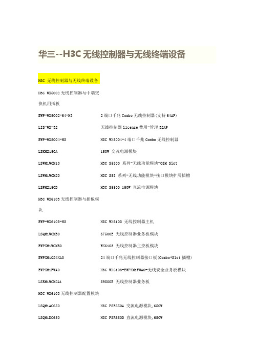
华三--H3C无线控制器与无线终端设备H3C WX5002无线控制器与中端交换机用插板EWP-WX5002-64-H32端口千兆Combo无线控制器(支持64AP)LIS-WX-32无线控制器license费用-管理32APEWP-WX5004-H3H3C WX5004-4端口千兆Combo无线控制器LSKM2150A150W 交流电源模块LSWM1WCM10H3C S5800 系列-无线功能模块-OSM SlotLSWM1WCM20H3C S58 系列-无线功能模块-接口模块扩展插槽LSPM2150D H3C S5500 150W 直流电源模块H3C WX6103无线控制器与插板模块EWP-WX6103-H3H3C WX6103 无线控制器主机LSQM1WCMB0S7500E 无线控制器业务板模块EWPXM1WCMB0WX6103 无线控制器主控板模块EWPXM1G24XA024端口千兆无线控制器接口板(Combo+Slot插槽) EWPXM1FWA0H3C WX6103-EWPXM1FWA0-无线安全业务板模块LSRM1WCM2A1S9500E 无线控制器业务板H3C WX6103无线控制器配置模块LSQM1AC650H3C PSR650A 交流电源模块,650WLSQM1DC650H3C PSR650D 直流电源模块,650WEWPXM1XP2P H3C WX6103-2端口万兆以太网XFP光接口模块EWPXM1XP1P H3C WX6103-1端口万兆以太网XFP光接口模块LIS-WX-128无线控制器license费用-管理128APH3C WA1208E-主机EWP-WA1208E-GP无线局域网单G模块大功率接入点EWP-WA1208E-GP-FIT无线局域网单G模块大功率接入点-FITH3C无线局域网接入点设备EWP-WA2110-AG-FIT H3C WA2110-AG-无线局域网AG双模单频可管理型接入点-FIT H3C WA2200-主机EWP-WA2210-AG H3C WA2210-AG 无线局域网室内型AG单频双模接入点EWP-WA2220-AG H3C WA2220-AG 无线局域网室内型AG双频双模接入点EWP-WA2220E-AG H3C WA2220E-AG 无线局域网增强型AG双频双模接入点H3C WA2220X-AGP 无线局域网室外型AG双频双模2.4GHz大功EWP-WA2220X-AGP率接入点EWP-WA2220E-AG-T H3C WA2220E-AG-T-车载无线接入点(MR)H3C WA2210X-GE-无线局域网室外增强型802.11b/g单频双模EWP-WA2210X-GE接入点EWP-WA2220X-AGE H3C WA2220X-AGE-无线局域网室外增强型AG双频双模接入点H3C WA2210E-GE,无线局域网增强型802.11b/g单频双模接入EWP-WA2210E-GE点EWP-WB2320X-AGE H3C WB2320X-AGE,无线网桥设备EWP-WA2200-WOU H3C WA2200-无线局域网接入点室外单元模块EWP-WA2210-AG-FIT H3C WA2210-AG 无线局域网室内型AG单频双模接入点-FIT EWP-WA2220-AG-FIT H3C WA2220-AG 无线局域网室内型AG双频双模接入点-FIT EWP-WA2210X-GE-FIT H3C WA2210X-GE-无线局域网室外增强型802.11b/g单频双模接入点-FITEWP-WA2220X-AGP-FITH3C WA2220X-AGP 无线局域网室外型AG双频双模2.4GHz大功率接入点-FITEWP-WA2220X-AGE-FITH3C WA2220X-AGE-无线局域网室外增强型AG双频双模接入点-FITEWP-WA2210E-GE-FITH3C WA2210E-GE-无线局域网增强型802.11b/g单频双模接入点-FITEWP-WA2220E-AG-FIT H3C WA2220E-AG 无线局域网增强型AG双频双模接入点-FIT EWP-WB2320X-AGE-FIT H3C WB2320X-AGE-无线网桥设备-FITEWP-WH2530X-DAG-FIT H3C WH2530X-DAG-无线Mesh设备-FITH3C 无线局域网2.4GHz天线组件-全向&定向天线-802.11b/gTQJ-SA800/2500-3全向天线-824~960/1710~2500MHz-3dBi-垂直-360DEG-50W-0r-N(F)-是TQJ-2400-11-T2全向天线-2400-2500MHz-11dBi-垂直极化-150W-2r-N型母头-自带支架TDJ-SA2400-11-90定向天线-2400~2500MHz-11dBi-90deg-Vertical--0r-300W-with support-N(female)-0.28mTQJ-2400BKF-Y定向天线-2.4~2.483GHz-8.5dBi-80度-垂直极化-50W-N-K-否SL13090A全向天线-2.4~2.5GHz-5dBi-垂直极化-全向-10W-N-K-否TQC-2400CI全向天线-2.4~2.483GHz-5.5dBi-垂直极化-50W-SMA-RP-否TDJ-2400IA(-45)定向天线,2.4~2.5GHz,15dBi,72deg,负45度,100W,N-K,是SL14011A定向天线,2.4~2.5GHz,15±1dBi,30±3deg,垂直极化,100W,N-K,否定向天线,2.4~2.5GHz,10±1dBi,55±3deg,垂直极SL14166A化,100W,N-K,否H3C 无线局域网5.8GHz天线组件-全向&定向天线-802.11a定向天线-5725~5850MHz-17dBi-25deg-垂直TDJ-DBS5800-17-50W-0r-N-Female-自带支架全向天线-5725~5850MHz-12dBi-垂直TQJ-5800-12-T0-12dBi-5W-0r-N(female)-自带支架定向天线-5.725~5.85GHz-29dBi-6度-垂直或水平-100W-N-K-TDJ-5800P6否全向天线-5.725~5.875GHz-5dBi-垂直极化-全向-100W-N-K-SL13089A否定向天线-2.4~2.5&5.15~5.85GHz-12&15dBi-45&20度-垂直极TDJ-2458BKC化-50W-N-K-否定向天线-2.4~2.5&5.15~5.85GHz-2.5&4.5dBi-360度-垂直极TQJ-2458XTJ1化-50W-N-K-否TDJ-5158BKT60-2定向天线-5150-5850MHz-17dBi-60°-垂直极化-50W-N型H3C 无线终端设备发货附件一次电源-0degC-40degC-100V-240V-48V/0.5A-AC电源线可拆FSP025-1AD207A卸CAB-PGND-Pwr-3m外部电源线-机箱PGND-12AWG-3m-(OT6-4)CAB-RF-0.2m-SMA射频电缆-0.2m-(SFF50-3)-(N50直公 to SMA50直母)CAB-RF-1.83m-(2*NSM+RG8/U)射频电缆-1.83m-50ohm-N50直公-(COAX-RG8/U)-N50直公CAB-RF-4.5m-(2*NSM+RG8/U)射频电缆-4.5m-50ohm-N50直公-(COAX-RG8/U)-N50直公CAB-RF-10m-(2*NSM+RG8/U)射频电缆-10m-50ohm-N50直公-(COAX-RG8/U)-N50直公射频电缆-1.83m-50ohm-N50直公-(COAX-RG8/U)-反极性SMA直CAB-RF-1.83m-(N+RG8+SMA)母射频电缆-6.1m-50ohm-N50直公-(COAX-RG8/U)-反极性SMA直CAB-RF-6.1m-(N+RG8+SMA)母射频同轴连接器-N-50ohm-直式-母-配接带N型头的电缆-双阴BNC-RF-N-50-KK转接器,外壳镀三元合金射频同轴连接器-N-50ohm-直式-公-配接N型接头的电缆-双阳N-50JJ转接器信号避雷器-2.5KA@8/20us-300V@Line-Earth-10/100MPOE-MHPoE-RJ45&48VDC JACKMHT6000-N-1天馈避雷器-10KA-20V-2.4~6.0GHz-100W-N-F/N-MSLPS-2504无源分路器-2G/3G-1分4功分器-800~2500MHz-N(F)-SLPS-2503无源分路器-一分三-微带线-800~2500MHz-N/female-无源SL21357B无源分路器-WLAN/3G-1分2功分器-1700~2500MHz-N(F)N-50JR负载-0~8GHz-50ohm-<1.25-2W-N MalePSMA-50KR负载-DC~12.4GHz-50ohm-<=1.25-1W-RSMA FemaleSFP-FE-BX15-U-SM1310SFP模块,-40~85℃,1310nm,15km,LCOP-DLC-10m-S光纤连接器-DLC(GM-8T)-SC*2-单模-7mm-10mEWPA-IM壁挂组件-WA2200OANT-2.4/5.8G H3C WA2200 室外天线安装套件OP-A H3C WA2200,室外电源安装套件EWP-WA2200-WOU H3C WA2200-无线局域网接入点室外单元模块CB-2412/2462MHz合路器-WLAN-2412/2462MHz-NFCAB-AC Pwr-5m-PS4M AC电源线-5m-(PI直公)-(227IEC53 RVV1.0^2(3C))-(PS4公) FSP025-1ADF07B一次电源--30℃-55℃-90VAC-264VAC-48V/0.52AH3C无线控制器用SFP模块SFP-GE-LH40-SM1310光模块-SFP-GE-单模模块-(1310nm,40km,LC)SFP-GE-LH40-SM1550光模块-SFP-GE-单模模块-(1550nm,40km,LC)SFP-GE-LH70-SM1550光模块-SFP-GE-单模模块-(1550nm,70km,LC)SFP-GE-SX-MM850-A光模块-SFP-GE-多模模块-(850nm,0.55km,LC)SFP-GE-LX-SM1310-A光模块-SFP-GE-单模模块-(1310nm,10km,LC)SFP-GE-LX-SM1310-BIDI光模块-SFP千兆BIDI光模块-TX1310/RX1490,10km,LCSFP-GE-LX-SM1490-BIDI光模块-SFP千兆BIDI光模块-TX1490/RX1310,10km,LCXFP-LX-SM1310光模块-XFP-10G-单模模块-(1310nm,10km,LC)XFP-SX-MM850光模块-XFP-10G-多模模块-(850nm,300m,LC)27,000.00XFP-LH40-SM1550-F1XFP万兆光模块(1550nm,40km,LC)H3C 有线无线一体化交换机设备H3C WX3024-PoEP-24端口千兆(4 SFP Combo+Slot插槽+PoE EWP-WX3024-POEP-H3Plus)有线无线一体化交换机LIS-WX-12有线无线一体化交换机license费用-管理12APH3C WX3010-PoEP-10端口千兆(8GE-T+2SFP)有线无线一体化交EWP-WX3010-POEP-H3换机1个WX3010有线无线一体化交换机捆绑10个WA2210-AG-FIT EWP-Z2-1无线局域网室内型AG单频双模接入点1个WX3024有线无线一体化交换机捆绑10个WA2210-AG-FIT EWP-Z2-2无线局域网室内型AG单频双模接入点3个WX3024有线无线一体化交换机捆绑10个WA2210-AG-FIT EWP-Z2-3无线局域网室内型AG单频双模接入点H3C WX3008-PoEP-8端口千兆(8GE-T+PoE Plus)有线无线一体EWP-WX3008-POEP-H3化交换机H3C 有线无线一体化交换机选配模块自带一个FLATPACK 1500电源模块和5根电缆的RPS冗余电源AC-RPS1000-A3(AC-RPS1000-A3,H3C面板),2个槽位可插2个电源模块CAB-RPS PoE-2m-JD5RPS电源线-2.0m-(大插头)-(SJTW2芯12AWG黑)-(大插头) LS5M1XP1PB H3C S5100EI 单端口万兆以太网光接口板(XFP)LS5-FL-B安装弯角组件H3C WA2600-主机H3C WA2610E-AGN 802.11n无线局域网增强型2.4/5GHz单频双EWP-WA2610E-AGN-FIT模接入点-FITH3C WA2620E-AGN 802.11n无线局域网增强型2.4&5GHz双频双EWP-WA2620E-AGN-FIT模接入点-FITH3C WA2610E-AGN 802.11n无线局域网增强型2.4/5GHz单频双EWP-WA2610E-AGN模接入点H3C WA2620E-AGN 802.11n无线局域网增强型2.4&5GHz双频双EWP-WA2620E-AGN模接入点H3C WA2620-AGN 802.11n无线局域网室内型2.4/5GH双频接入EWP-WA2620-AGN点H3C WA2620-AGN 802.11n无线局域网室内型2.4/5GH双频接入EWP-WA2620-AGN-FIT点-FITH3C WA2612-AGN 802.11n无线局域网室内型2.4/5GHz单频接EWP-WA2612-AGN-FIT入点-FITH3C WA2612-AGN 802.11n无线局域网室内型2.4/5GHz单频接EWP-WA2612-AGN入点EWP-WA2610-AGN-FITH3C WA2610-AGN 802.11n无线局域网室内型2.4/5GHz单频接入点-FITEWP-WA2610-AGNH3C WA2610-AGN 802.11n无线局域网室内型2.4/5GHz单频接入点H3C WA2600-天线TQJ-2458MIC×6全向天线-2.4G~2.5GHz,5.15G~5.85GHz-2.5dBi@2.4G,4.5dBi@5G-全向-50W-RPSMA-吸顶安装内置6天线TQJ-2458MIK×3全向天线-2.4G~2.483GHz,5.15G~5.85GHz-2.5dBi@2.4G,4dBi@5G-全向-50W-RPSMA-吸顶安装内置3天线H3C WA2600-发货附件POE-3信号避雷器-3KA@8/20us-350V@Line-Ground-33.6W-1000MPoE-RJ45&48VDC JACKH3C 11n无线网卡EWP-WN612H3C WN612-11n 双频USB无线网卡无线控制器选配电源线CAB-DC Pwr-5m直流电源线-5m-6mm^2-(2*OT6-4)-(227IEC02-6^2蓝+227IEC02-6^2黑)-(2*OT6-6)CAB-DC Pwr-10m直流电源线-10m-10mm^2-(2*OT10-4)-(227IEC02-10^2蓝+227IEC02-10^2黑)-(2*OT10-6)CAB-DC Pwr-20m-2*(OT+T6)外部直流电源线-20m-5.3mm^2-蓝/黑-(2*OT6-4)-(10UL10455蓝+10UL10455黑)-(2*T6^2B)。
高中生物教学仪器盘点表(高级中学)
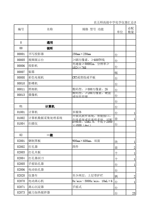
支 支 支 支 个 个 个 个 个 个 个 个 个 个 个 个 个 个 个 个 个
30 10 2 3 50 50 100 50 100 100 20 10 50 30 50 5 50 15 50 5
62 62001 62001 62001 62002 62003 62004 62005 62006 62007 酒精灯 酒精灯 酒精灯 干燥塔 气体洗瓶 抽滤瓶 抽气管 干燥器 气体发生器
金属酒精灯 酒精喷灯 电加热器 蒸馏水器 蒸馏水器 列管式烘干器 烘干箱 电冰箱 水浴锅 保温漏斗 注射器 注射器 注射器 塑料洗瓶 试剂瓶托盘 实验用品提篮 塑料水槽 碘升华凝华管 聚光小手电筒 ≥150L 铜制 铜制 5mL,塑料 50mL,塑料 100mL 250mL 座式,铜制 密封式
个 个 个 台 台 台 台 台 个 个 只 只 只 个 50 80 13 50 50 50 25 1 2 1 4 1
套 套
523 52340 52356 52357
多件 实验室管理用,网络版
套 套 套 套
6 60
玻璃仪器 计量
套
1
60001 60001 60001 60001 60001 60001 60012 60023 60023 60023 60023 60023 60041 60041 60041 60041 60041 60052 60052 60052 60052
套 套 套 套
1 1 1 1
包括金刚石、石墨、碳-60三 套 种结构模型;小型,球管式, 球直径不小于30mm 套 球直径不小于25mm 球直径不小于25mm 球直径不小于30mm S、SP、SP2、SP3、Px、Py、 Pz 套 套 套 套 个 个 个 个 个
- 1、下载文档前请自行甄别文档内容的完整性,平台不提供额外的编辑、内容补充、找答案等附加服务。
- 2、"仅部分预览"的文档,不可在线预览部分如存在完整性等问题,可反馈申请退款(可完整预览的文档不适用该条件!)。
- 3、如文档侵犯您的权益,请联系客服反馈,我们会尽快为您处理(人工客服工作时间:9:00-18:30)。
Product data sheet Supersedes data of 2003 Jun 172004 Nov 04PNP low V CEsat (BISS) transistorPBSS5250XFEATURES•SOT89 (SC-62) package•Low collector-emitter saturation voltage V CEsat •High collector current capability: I C and I CM •Higher efficiency leading to less heat generation •Reduced printed-circuit board requirements.APPLICATIONS •Power management –DC/DC converters –Supply line switching –Battery charger –LCD backlighting.•Peripheral drivers–Driver in low supply voltage applications (e.g. lamps and LEDs).–Inductive load driver (e.g. relays, buzzers and motors).DESCRIPTIONPNP low V CEsat transistor in a SOT89 plastic package. NPN complement: PBSS4250X.MARKINGNote1.* = p: Made in Hong Kong* = t: Made in Malaysia * = W: Made in China.TYPE NUMBER MARKING CODE (1)PBSS5250X *1LPINNINGPIN DESCRIPTION1emitter 2collector 3baseQUICK REFERENCE DATA SYMBOL PARAMETERMAX.UNIT V CEO collector-emitter voltage −50V I C collector current (DC)−2A I CM peak collector current −5A R CEsat equivalent on-resistance160m ΩPNP low V CEsat (BISS) transistorPBSS5250XORDERING INFORMATION LIMITING VALUESIn accordance with the Absolute Maximum Rating System (IEC 60134).Notes1.Device mounted on a FR4 printed-circuit board; single-sided copper; tin-plated; standard footprint.2.Device mounted on a FR4 printed-circuit board; single-sided copper; tin-plated; mounting pad for collector 1 cm 2.TYPE NUMBER PACKAGENAME DESCRIPTIONVERSION PBSS5250XSC-62plastic surface mounted package; collector pad for good heat transfer; 3 leadsSOT89SYMBOL PARAMETERCONDITIONSMIN.MAX.UNITV CBO collector-base voltage open emitter −−50V V CEO collector-emitter voltage open base −−50V V EBO emitter-base voltage open collector−−5V I C collector current (DC)−−2A I CM peak collector current T j(max)−−5A I B base current (DC)−−0.5A P tottotal power dissipationT amb ≤ 25 °C note 1−550mW note 2−1W T stg storage temperature −65+150°C T j junction temperature −150°C T amb ambient temperature−65+150°CPNP low V CEsat (BISS) transistorPBSS5250XTHERMAL CHARACTERISTICS Notes1.Device mounted on a FR4 printed-circuit board; single-sided copper; tin-plated; standard footprint.2.Device mounted on a FR4 printed-circuit board; single-sided copper; tin-plated; mounting pad for collector 1 cm 2.3.Device mounted on a FR4 printed-circuit board; single-sided copper; tin-plated; mounting pad for collector 6 cm 2.4.Device mounted on a ceramic printed-circuit board 7 cm 2, single-sided copper, tin-plated.SYMBOL PARAMETERCONDITIONS VALUEUNIT R th(j-a)thermal resistance from junction to ambientin free air note 1225K/W note 2125K/W note 390K/W note 480K/W R th(j-s)thermal resistance from junction to soldering point16K/WPBSS5250X PNP low V CEsat (BISS) transistorPNP low V CEsat (BISS) transistorPBSS5250XCHARACTERISTICST amb = 25 °C unless otherwise specified.Note1.Pulse test: t p ≤ 300 μs; δ ≤ 0.02.SYMBOL PARAMETERCONDITIONSMIN.MAX.UNIT I CBO collector-base cut-off current V CB = −50 V; I E = 0 A−−100nA V CB = −50 V; I E = 0 A; T j = 150 °C −−50μA I CES collector-emitter cut-off current V CE = −50 V; V BE = 0 V −−100nA I EBO emitter-base cut-off current V EB = −5 V; I C = 0 A −−100nAh FEDC current gainV CE = −2 V I C = −0.1 A 200−I C = −0.5 A 200−I C = −1 A; note 1200−I C = −2 A; note 1100−V CEsatcollector-emitter saturation voltageI C = −0.5 A; I B = −50 mA −−90mV I C = −1 A; I B = −50 mA −−250mV I C = −2 A; I B = −100 mA −−380mV I C = −2 A; I B = −200 mA; note 1−−320mV R CEsat equivalent on-resistance I C = −2 A; I B = −200 mA; note 1−160m ΩV BEsat base-emitter saturation voltage I C = −2 A; I B = −100 mA −−1.1V V BEon base-emitter turn-on voltage V CE = −2 V; I C = −1 A −1.1−V f T transition frequency I C = −100 mA; V CE = −5 V; f = 100 MHz100−MHz C c collector capacitanceV CB = −10 V; I E = i e = 0 A; f = 1 MHz−35pFPBSS5250X PNP low V CEsat (BISS) transistorPACKAGE OUTLINEPNP low V CEsat (BISS) transistorPBSS5250XDATA SHEET STATUSNotes1.Please consult the most recently issued document before initiating or completing a design.2.The product status of device(s) described in this document may have changed since this document was publishedand may differ in case of multiple devices. The latest product status information is available on the Internet at URL . DOCUMENT STATUS (1)PRODUCT STATUS (2)DEFINITIONObjective data sheet Development This document contains data from the objective specification for product development.Preliminary data sheet Qualification This document contains data from the preliminary specification. Product data sheet ProductionThis document contains the product specification.DISCLAIMERSGeneral ⎯ Information in this document is believed to be accurate and reliable. However, NXP Semiconductors does not give any representations or warranties,expressed or implied, as to the accuracy or completeness of such information and shall have no liability for the consequences of use of such information.Right to make changes ⎯ NXP Semiconductors reserves the right to make changes to informationpublished in this document, including without limitation specifications and product descriptions, at any time and without notice. This document supersedes and replaces all information supplied prior to the publication hereof.Suitability for use ⎯ NXP Semiconductors products are not designed, authorized or warranted to be suitable for use in medical, military, aircraft, space or life support equipment, nor in applications where failure or malfunction of an NXP Semiconductors product can reasonably be expected to result in personal injury, death or severe property or environmental damage. NXP Semiconductors accepts no liability for inclusion and/or use of NXP Semiconductors products in such equipment orapplications and therefore such inclusion and/or use is at the customer’s own risk.Applications ⎯ Applications that are described herein for any of these products are for illustrative purposes only. NXP Semiconductors makes no representation or warranty that such applications will be suitable for the specified use without further testing or modification.Limiting values ⎯ Stress above one or more limiting values (as defined in the Absolute Maximum Ratings System of IEC 60134) may cause permanent damage tothe device. Limiting values are stress ratings only and operation of the device at these or any other conditions above those given in the Characteristics sections of this document is not implied. Exposure to limiting values for extended periods may affect device reliability.Terms and conditions of sale ⎯ NXP Semiconductors products are sold subject to the general terms and conditions of commercial sale, as published at /profile/terms, including those pertaining to warranty, intellectual property rightsinfringement and limitation of liability, unless explicitly otherwise agreed to in writing by NXP Semiconductors. In case of any inconsistency or conflict between information in this document and such terms and conditions, the latter will prevail.No offer to sell or license ⎯ Nothing in this document may be interpreted or construed as an offer to sell products that is open for acceptance or the grant, conveyance or implication of any license under any copyrights, patents or other industrial or intellectual property rights.Export control ⎯ This document as well as the item(s) described herein may be subject to export controlregulations. Export might require a prior authorization from national authorities.Quick reference data ⎯ The Quick reference data is an extract of the product data given in the Limiting values and Characteristics sections of this document, and as such is not complete, exhaustive or legally binding.NXP SemiconductorsCustomer notificationThis data sheet was changed to reflect the new company name NXP Semiconductors, including new legal definitions and disclaimers. No changes were made to the technical content, except for package outlinedrawings which were updated to the latest version.Contact informationFor additional information please visit: For sales offices addresses send e-mail to: salesaddresses@© NXP B.V. 2009All rights are reserved. Reproduction in whole or in part is prohibited without the prior written consent of the copyright owner.The information presented in this document does not form part of any quotation or contract, is believed to be accurate and reliable and may be changed without notice. No liability will be accepted by the publisher for any consequence of its use. Publication thereof does not convey nor imply any license under patent- or other industrial or intellectual property rights.Printed in The Netherlands R75/02/pp9 Date of release: 2004 Nov 04 Document order number: 9397 750 13886分销商库存信息:NXPPBSS5250X,115PBSS5250X,135。