TENTEC气动泵
埃森·坦恩 Jockey Lite 泵控制器 BR124002EN 说明书

Pressure switch based jockey pump controller2 BR124002EN June 2018 Jockey Lite pump controllers Product descriptionAcross the lineJockey pump controllersThe JOCKEY Lite - Jockey Pump Controllers operate across-the-line. Full voltage is applied to the motor for starting bythe use of a single motor starter. Starting inrush current isapproximately 600% of rated full load amperes.Product featuresCombination Motor Controllers - All JOCKEY Lite controllersare supplied with EATON combination motor controllers,which combine the circuit breaker and overload inone device.Sealed rotary handleMechanismThe rotary handle mechanism can be padlocked in theOFF position. The rotary handle mechanism does not allowthe door to be opened when turned to the ON position.XT Power controlsThe JOCKEY Touch - Jockey PumpControllers incorporateEaton’s XT Power Controls which are designed for theglobal marketplace. The XT controls carry global ratings, aresmall in size and are available in a wide variety of operatingvoltages. They are easy to install and maintain, due to their modular, plug-in design.120V Control power transformer All JOCKEY Lite pump controllers are wired with a 120V control power transformer as standard.NEMA 2 enclosures Enclosures have an oven baked powder paint finish and are supplied with NEMA 2 rating, unless otherwise ordered. Available options include: NEMA 3R, 3, 4, 4X, 12.Starting methods There are two methods of starting the controller: Auto and Hand.Dual Setting Pressure Switch A dual setting 15-290 PSI pressure switch is used to sense a drop in pressure which actuates the jockey pump contac-tor. The setting adjustment screws are used for setting the pressure range and differential. There is one set of form-Coutput contacts rated at 10A.3Jockey Lite pump controllersBR124002EN June 2018 Technical dataAcross-the-line (direct on line)Jockey pump controllersLine voltage200-208V220-240V380-415V 440-480V 550-600V 120V-1Ph 240V-1Ph Motor horsepower 1/3-20Hp1/3-20Hp 1/3-40Hp 1/3-50Hp 1/3-50Hp 1/3-2Hp 1/3-5Hp Standards & certifi cationThe JOCKEY Lite - Jockey Pump Controllers meet the requirements of the latest edition of NFPA 20 as well as meeting CE mark requirements. They meet or exceed the requirements of UL 508 [Underwriters Laboratories (UL)] and are approved by [Canadian Standards Association (CSA)].200-208V220-240V380-415V440-480V550-600VMotor HP WithstandRating (kA)Motor HP WithstandRating (kA)Motor HP WithstandRating (kA)Motor HP WithstandRating (kA)Motor HP WithstandRating (kA)15 - 2010015 - 2010020 - 4010025 - 5010040 - 5025 120V 1ph208V 1ph240V 1ph Approx. WeightMotor HP WithstandRating (kA)Motor HP WithstandRating (kA)Motor HP WithstandRating (kA)Lbs (Kg)3 - 5100 5 - 101007.5 - 1010055 (25)200-208V220-240V380-415V440-480V550-600VMotor HP WithstandRating (kA)Motor HP WithstandRating (kA)Motor HP WithstandRating (kA)Motor HP WithstandRating (kA)Motor HP WithstandRating (kA)15 - 2010015 - 2010020 - 4010025 - 5010040 - 5025 120V 1ph208V 1ph240V 1ph Approx. WeightMotor HP WithstandRating (kA)Motor HP WithstandRating (kA)Motor HP WithstandRating (kA)Lbs (Kg)3 - 5100 5 - 101007.5 - 1010055 (25)Line terminals (incoming cables)Line voltage Qty. & cable sizes Qty. & cable sizes200 - 208220 - 240380 - 415*440 - 480550 - 600Ground lugMax HP1010152030(1) #14 - 6 (CU/AL)(4) #14 - 2 (CU/AL) 2020405050(1) #14 - 1/0 (CU/AL)(4) #14 - 2 (CU/AL)Load terminals (to motor)Line voltage Qty. & cable sizes200 - 208220 - 240380 - 415*440 - 480550 - 600Single Run Double RunMax HP23557.5(1) #18 - 14 (CU/AL)(2) #18 - 14 (CU/AL) 1010152030(1) #14 - 8 (CU/AL)(2) #14 - 8 (CU/AL)2020405050(1) #14 - 2 (CU/AL)For proper cable size, refer to the most recent edition of the National Electric Code (NEC - NFPA 70)Option Selection GuideTD124016ENXTJL Jockey pump controllersFeaturesPS124001ENXTJL Jockey pump controllersT ypical specificationsApprovalsThe Jockey Pump Controller shall meet the requirements of the latest edition of NFPA 20 as well as meetingCE mark requirements. It shall meet or exceed therequirements of UL 508 [Underwriters Laboratories(UL)] standards and approved by [Canadian StandardsAssociation (CSA)].Starting typeThe controller shall be Across-the-Line type for full voltage starting.RatingsThe Controller shall have a withstand rating of 10,000symmetrical amperes @ [208V] [240V] [380V] [400V][415V] [480V] [600V] [120V single phase] [240V singlephase]The horsepower rating of the controller shall not exceed 50Hp for three (3) phase units or 10Hp for single (1) phase units.ConstructionThe controller shall include a combination Circuit Breaker/ Overload Motor Protector.The motor circuit protector shall be mechanicallyinterlocked such that the enclosure door cannot be opened when the handle is in the ON position except by a tooloperated defeater mechanism.The controller manufacturer shall manufacture thecontactor, circuit breaker, pushbuttons, and enclosures.Brand labeled components will not be accepted.Supply VoltageThe jockey pump controller shall be available in following supply voltages:A 200-208V50/60HzB 220-240V50/60HzC 380V50/60HzD 440-480V50/60HzE 550-600V50/60HzF 415V50/60HzG1 120V single phaseG2 240V single phaseJ 400V50HzK400V60Hz EnclosureThe controller shall be housed in a NEMA Type 2 (IEC IP11) drip-proof, powder baked finish, freestanding enclosure.Optional Enclosures:NEMA 3R (IEC IP14) rain-tight enclosureNEMA 4 (IEC IP66) watertight enclosureNEMA 4X (IEC IP66) watertight 304 stainless steelenclosureNEMA 4X (IEC IP66) watertight 316 stainless steelenclosureNEMA 4X (IEC IP66) watertight corrosion resistantenclosureNEMA 12 (IEC IP52) dust-tight enclosureRun Period TimerAn optional Run Period Timer shall be available.LanguagesThe controller shall be available in a variety of languages including, but not limited to:English, French, Spanish, Portuguese, Turkish.OptionsThe jockey pump controller shall have provisions to besupplied with the following options:C1 Extra Contacts “Pump Run”C2 Extra Contacts “AC Power Failure”E1 NEMA 3R - Raintight EnclosureE2 NEMA 4 - Watertight EnclosureE3 NEMA 12 - Industrial Dust Tight EnclosureE5 NEMA 4X - 304 Stainless Steel EnclosureE8 TropicalizationE9 NEMA 4X - Painted SteelE10 NEMA 4X - 316 Stainless SteelEX Export CratingPOL “Power On” LightPRL “Pump Run” LightP7 Low Suction Pressure Switch and LightP8 Low Suction ShutdownR1 Space Heater (120/240V)R2 Space Heater c/w ThermostatR3 Space Heater c/w HumidistatS SequentialStartTimerT RunPeriodTimerZ ElapsedTimeMeterJockey Lite pump controllerFeaturesManufacturerThe controller shall be of the XT JL Across-the-Line type as manufactured by EATON.2 PS124001EN June 2018 。
派克精密流体微型泵说明书
您与运动和控制技术领域的先行者合作,就是希望促进您的业务发展和全球的发展。
从微型电磁阀到高集成型自动化系统,我们的产品对于用于药物研发和病原体检测的救生医疗设备和科学仪器至关重要。
并且对于缩短上市时间和降低总体拥有成本也十分关键。
因此,请与派克合作,准备改变这一切吧!/precisionfluidics 1 603 595-1500目录页T2-05Helix124高效和紧凑型 13.5mm 宽泵 – 高达 800 mLPM高压泵 – 超过5.5 LPM 和高达100 PSI 的压力T2-0320高性能与尺寸比率泵 – 高达2.5 LPMLTC 系列76液体系列传送泵 – 高达 650 mLPMEZ 底座92振动隔离安装系统小型活塞泵(空气)微型泵(空气/气体)微型泵(液体)T2-0494超紧凑型、高效泵 – 高达 7.5LPMBTC-IIS 系列62应用广泛的多功能双头泵系列产品 – 高达 11 LPMBTC 系列52应用广泛的多功能泵系列产品 – 高达6 LPMLTC-IIS 系列84液体系列双头传送泵 – 高达1.5 LPMCTS 系列BTX-Connect 2836高性能紧凑型 20 mm 宽泵 – 高达 2.5 LPM多功能双头和单头泵系列,适合多种应用-高达10 LPMTTC 系列74紧凑、高效、低压泵 – 高达 6 LPMTTC-IIS 系列84紧凑、高效、低压双头泵 - 高达 11 LPM附件4Helix 微型高压泵高达100 PSI (6.9 bar)压力Parker Helix 是一款紧凑型高压泵,旨在实现小型即时临床护理仪器。
Helix 可在挑战性的高海拔环境和无法使用外部压缩空气的应用中实现高压操作。
Helix 泵可提供5.5 LPM 以上的流量和高达100 PSI (6.9 bar)的压力,为性能至关重要且空间有限的台式诊断设备提供了出色的解决方案。
• 集成了用于卸荷的X 阀,可实现高压重启• 内部飞轮可在高压下低速运行• 无油活塞• 简单的安装特性• 带有推入式接头的快速流体连接• 符合RoHS 指令和REACH 标准产品特性• 液上空气• 气动驱动•微流控芯片• 即时临床护理检验• 分子诊断• 核酸纯化•基因组学典型应用典型市场产品规格物理特性电子5微型隔Helix 微型高压泵典型流量曲线• 曲线展示了0.080"偏移泵的流量性能• 使用5.0 Vdc 控制输入时,泵将以大约4400 RPM 的转速和高达8.5 LPM的流量的状态运行,但不建议连续工作。
01德国斯维因泵性能参数

4
4
动力
型式
柴油机
电动机
柴油机
功率(kW)
111
90
161
液压系统
型式
开式液压回路系统
主泵型号
A8V80SRH
2×A7V080
其它
操纵方式
手动或摇控操作
整机重量(带燃油,t)
5
5
7
(2)机构特性表
项目
BP2000RD-20
BP2000RE-20
BP3500HDR
-200/125D
混凝土泵送系统
泵送机构
BP系列混凝土泵
(德国SCHWING)
(1)主要技术性能表
项目
BP2000RD-20
BP2000RE-20
BP3500HDR
-200/125D
规格
混凝土输出量(m3/h)
51
87
51
87
52
89
最大泵送压力(Mpa)
10.0
5.6
10.0
5.6
13.5
8.0
泵送性能
输送管直径(mm)
100/125/150
(3)外形尺寸(mm)
符号
名称
单位
BP2000RDR
-200/125D
A
长度
mm
6000
6900
B
宽度
mm
1900
1950
C
高度
mm
1920
2000
D
接料斗离地高度
mm
E
轮距
mm
100/125/150
150
最大输送水平距离(m)
最大输送垂直距离(m)
全国隔膜泵十大品牌气动隔膜泵品牌前十排名

全国隔膜泵十大品牌气动隔膜泵品牌前十排名1.上海沈泉泵阀制造有限公司上海沈泉泵阀制造有限公司是一家专业生产,销售管道泵,排污泵,消防泵,化工泵等给排水设备的厂家,产品涉及工矿企业、农业、城市供水、石油化工、电站、船舶、冶金、高层建筑、消防供水、工业水处理和纯净水、食品、制药、锅炉、空调循环系统等行业领域。
2. 欧隆泵业股份有限公司欧隆泵业股份有限公司成立于2009年,本公司是一家专业生产泵类产品的企业;高品质的生产设备,完善的检测标准,专业的技术力量,形成了集研发设计、生产、销售和服务为一体的现代化企业。
公司主营污水泵、油浸泵、管道泵、潜水泵等产品。
产品广泛应用于农林灌溉、区域防汛、城市排水、建筑工程、污水处理的相关领域,深受客户好评。
3. 射阳县苏工泵阀厂射阳县苏工泵阀厂(始创于一九七五年)是一家专业制造泵类产品现代化企业,经过多年的创业发展,并拥有现代化最先进的电脑微机测试系统,现在是国内最先进单位。
技术力量雄厚,吸收国内外最先进的技术,采用国内和国外相结合的材料,铸铁、耐热耐腐钢、不锈钢、耐腐耐磨氟塑料合金、增强聚丙烯、耐腐蚀、耐高温、无泄露、研制成高效节能产品填补了国内外的空白。
替代了进口泵。
产品广泛用于:化工、冶金、制药、印染、电力、石油、食品、制冷、消防、暖通、国防军工、污水处理等。
并为国家一些重点工程、工业、农业、给排、环保、交通与能源开采等做出贡献。
专业生产FS型塑料离心泵、FP型增强聚炳烯离心泵、FSB-L型氟塑料合金离心泵、AFB型耐腐蚀离心泵、IHF、IH 型化工离心泵、UHB-ZK型耐腐耐磨砂浆泵、HTB-ZK型耐酸陶瓷泵、FYS型耐腐耐磨液下泵、W型旋涡泵、GC型多级离心泵、IS、IR型清水离心泵、NWL、GWL型立式泥浆泵等、泵用配件及泵用机械密封.。
开拓.奋进中的苏工泵阀厂坚持奉行以人为本的理念,诚实守信,以质取胜,薄利多销,供货及时的经营方针及完善的售后服务,深受广大客商的一致好评。
中国最新气动隔膜泵十大品牌排行榜
中国最新气动隔膜泵十大品牌排行榜
①上海沈泉泵业(中国水泵行业后起之秀,不锈钢泵品质好,在化工、市政、建筑、暖通、电厂等领域业绩不错,上海沈泉泵阀制造有限公司)
②连成 (中国驰名商标,上海市名牌产品,在市政、建筑、暖通、电厂等领域业绩不错,上海连成(集团)有限公司)
③凯泉(中国驰名商标,上海市著名商标,在市政、建筑、暖通、电梁禅轿厂等领域业绩不错,上海凯泉泵业(集团)有限公司)
④南方(中国驰名商标,浙江省著名商标,特泵、不锈钢多级泵做的很不错,南方泵业股份有限公司)
⑤东方(上海市著名商标,在建筑领域近两年销量很大,上海东方泵业(集团)有限公司)
⑥博山(驰名商标,山东省著名商标,在钢铁、电力、煤炭等领域业绩不错,山东博泵科技股份有限公司)
⑦新界(中国驰名商标,浙江名牌,农用水泵行业龙头企业,浙江新界泵业股份有限袭伍公司)
⑧熊猫(上海市著名商标,在建筑领域近两年销量很大,上海熊猫机械(集团)有限公司)
⑨双轮(中国驰名商标,山东省著名商标,在油田、石化、矿山、热电等领域业绩不错,上山东双轮股份有限公司)
⑩肯富来(广东省著名商标,广东省名牌,液环真空泵的始创者,广东省佛山水泵厂有限公司)
国产泵业其它品牌:广一、沈阳水泵厂、重庆水泵厂、湘电长沙水泵厂、利欧、化成HCH、凌霄、深蓝、开利、亚梅、安波、兴齐、奥利、石家庄泵业、大耐泵业、三鱼
世界十大水泵品牌
1、美国FLOWSERVE
2、德国威乐
3、美国滨特尔
4、德国凯士比(KSB)
5、日本荏原
6、德国普罗名特
7、美国ITT
8、意大利艾格尔集团
9、丹麦格兰富
10、德国耐驰集团。
芬士汽气阀门Tiger 2000说明书

Solenoid/pneumatic valves, Tiger 20002d Internet: /catalogue/...Subject to change – 2023/05Solenoid/pneumatic valves, Tiger 2000Key featuresGeneral• A complete and comprehensive range with 5/2-way and 5/3-way valves• Poppet valve for monostable func-tions or piston spool for more com-plex versions with air spring and 5/3-way valves• With flow-optimised internal func -tions for higher flow rates with the same width• Pneumatic connections G1/8, G1/4, G3/8• Diverse and flexible, side and front mounting• Pneumatic or electrical actuation • Versatile electrical connection tech-nology with F or V solenoid coil with low power consumption, can also be used with valve terminals• Functional and timeless design,enclosed front housingSolenoid coils F solenoid coilsVoltage:• 12 to 230 V DC• 12 to 240 V AC (50 to 60 Hz)Power consumption:• 4.1 to 5.5 W DC • 3.85 to 9 VA AC• For all MFH valves• Selected types conform to the ATEX Directive for potentially explosive atmospheres• Solenoid coil can be easily exchanged later• Solenoid coil not included in scope of deliveryV solenoid coils Voltage: • 24 V DCPower consumption:• 2.5 W • For all MVH valves • Low heating • Solenoid coil included in scope of deliveryManifold assembly With manifold rail PALWith manifold block PRSThe valves Tiger 2000 (without an ATEX category) can be mounted on manifold rails PAL with a common supply port or on manifold blocks PRS with a common supply port and common exhausts.The manifold rail and manifold block have 2 to 10 valve positions.H- -NoteValves for potentially explosiveatmospheres (ATEX category) are not suitable for mounting on manifold rails PAL or manifold blocks PRS.Block mounting of Tiger 2000 valves in potentially explosive atmospheres is only recommended in combination with PRS-... manifold rails.Solenoid/pneumatic valves, Tiger 2000 Product range overview3 2023/05 – Subject to change d Internet: /catalogue/...4d Internet: /catalogue/...Subject to change – 2023/05Solenoid valves, Tiger 2000Peripherals overviewMounting on manifold block14Variants MFH-5-...-BMVH-5-...-BSolenoid valves, Tiger 2000 Peripherals overview5 2023/05 – Subject to change d Internet: /catalogue/...6d Internet: /catalogue/...Subject to change – 2023/05Solenoid valves, Tiger 2000Peripherals overviewMounting on manifold rail14Variants MFH-5-...-BMVH-5-...-BSolenoid valves, Tiger 2000 Peripherals overview7 2023/05 – Subject to change d Internet: /catalogue/...Solenoid valves, Tiger 2000Type codes8d Internet: /catalogue/...Subject to change – 2023/05Solenoid valves MFH-B, Tiger 2000 Technical data – 5/2-way valves-M-Flow rate Array 750 ... 2000 l/min-P- Voltage12, 24, 42, 48 V DC24, 42, 48, 110, 230,240 V ACSets of wearing partspage 13a1)9 2023/05 – Subject to change d Internet: /catalogue/...10d Internet: /catalogue/...Subject to change – 2023/05Solenoid valves MFH-B, Tiger 2000Technical data – 5/2-way valves1)For non-reversible valves2)Corrosion resistance class CRC 1 to Festo standard FN 940070Low corrosion stress. Dry indoor application or transport and storage protection. Also applies to parts behind coverings, in the non-visible interior area, and parts which are covered in the application (e.g. drive trunnions).1)For reversible valvesMaterialsSectional view11) F solenoid coils a page 64-M-Flow rate1000 ... 2000 l/min -P- Voltage12, 24, 42, 48 V DC24, 42, 48, 110, 230,240 V AC1)ATEX valve1)Corrosion resistance class CRC 1 to Festo standard FN 940070Low corrosion stress. Dry indoor application or transport and storage protection. Also applies to parts behind coverings, in the non-visible interior area, and parts which are covered in the application (e.g. drive trunnions).1)For reversible valvesMaterialsSectional view11) F solenoid coils a page 64Technical data – 5/3-way valves -M-Flow rate1000 ... 2600 l/min-P- Voltage12, 24, 42, 48 V DC24, 42, 48, 110, 230,240 V AC1)ATEX valve1)Corrosion resistance class CRC 1 to Festo standard FN 940070Low corrosion stress. Dry indoor application or transport and storage protection. Also applies to parts behind coverings, in the non-visible interior area, and parts which are covered in the application (e.g. drive trunnions).1)With external pilot air supply and/or ATEX valves2)After long electrical actuation (> 16h), the switch-off time of 5/3-way valves can increase to max. 50 ms.3)After long electrical actuation (> 16h), the switch-off time of 5/3-way valves can increase to max. 100 ms.4)After long electrical actuation (> 16h), the switch-off time of 5/3-way valves can increase to max. 150 ms.MaterialsSectional view11) F solenoid coils a page 641) F solenoid coils a page 64-M-Flow rate750 ... 2000 l/min -P- Voltage24 V DCSets of wearing partsa page 381)Corrosion resistance class CRC 1 to Festo standard FN 940070Low corrosion stress. Dry indoor application or transport and storage protection. Also applies to parts behind coverings, in the non-visible interior area, and parts which are covered in the application (e.g. drive trunnions).1)Values for MVH-5-1/4-B-VI-XMaterialsSectional view1-M-Flow rate1000 ... 2000 l/min-P- Voltage24 V DCSets of wearing partsa page 371)Corrosion resistance class CRC 1 to Festo standard FN 940070Low corrosion stress. Dry indoor application or transport and storage protection. Also applies to parts behind coverings, in the non-visible interior area, and parts which are covered in the application (e.g. drive trunnions).MaterialsSectional view 1-M-Flow rate1000 ... 2600 l/min -P- Voltage24 V DC1)Solenoid valve MVH-5/3G-3/8-B1)Corrosion resistance class CRC 1 to Festo standard FN 940070Low corrosion stress. Dry indoor application or transport and storage protection. Also applies to parts behind coverings, in the non-visible interior area, and parts which are covered in the application (e.g. drive trunnions).1)With external pilot air2)After long electrical actuation (> 16h), the switch-off time of 5/3-way valves can increase to max. 50 ms.3)After long electrical actuation (> 16h), the switch-off time of 5/3-way valves can increase to max. 100 ms.4)After long electrical actuation (> 16h), the switch-off time of 5/3-way valves can increase to max. 150 ms.MaterialsSectional view 1Solenoid valves MVH-B, Tiger 2000 Technical data – 5/3-way valvesSolenoid valves MVH-B, Tiger 2000 Technical data – 5/3-way valvesSolenoid valves MVH-B, Tiger 2000 Technical data – 5/3-way valvesPneumatic valves, Tiger 2000Peripherals overviewMounting on manifold block Mounting on manifold rail5Pneumatic valves, Tiger 2000Type codesPneumatic valves VL, Tiger 2000 Technical data – 5/2-way valves -M-Flow rate750 ... 2000 l/minSets of wearing partsa page 49Pneumatic valves VL, Tiger 2000 Technical data – 5/2-way valves1)Corrosion resistance class CRC 1 to Festo standard FN 940070Low corrosion stress. Dry indoor application or transport and storage protection. Also applies to parts behind coverings, in the non-visible interior area, and parts which are covered in the application (e.g. drive trunnions).Pneumatic valves VL, Tiger 2000 Technical data – 5/2-way valvesPneumatic valves VL, Tiger 2000 Technical data – 5/2-way valvesPneumatic valves J, Tiger 2000Technical data – 5/2-way valves, double pilot valves-M-Flow rate1000 ... 2000 l/min1)Corrosion resistance class CRC 1 to Festo standard FN 940070Low corrosion stress. Dry indoor application or transport and storage protection. Also applies to parts behind coverings, in the non-visible interior area, and parts which are covered in the application (e.g. drive trunnions).。
气动泵用途

气动泵用途
气动泵是一种通过压缩空气进行工作的泵类设备,其工作原理是利用空气做动力源,通过压缩和弹性等特性实现液体输送。
气动泵广泛应用于化工、石化、制药、食品、污水处理和环保等领域。
具体来说,它可以泵送各种腐蚀性介质、高温介质、易燃介质和高粘度介质等。
同时,气动泵的安全性能比较高,由于其驱动部分不使用电动点火设备,因此在易燃易爆环境下使用更加安全可靠。
此外,气动泵还适用于矿井、隧道、水利、地铁、建筑、桥梁等施工地点的注浆堵水、填充空隙、加固破碎岩层等工程,配合多组分化工类系列产品进行施工。
请注意,气动泵的具体用途可能因实际的应用场景和需求而有所不同。
在选择和使用气动泵时,需要根据实际需求和用途选择合适的泵体材料、最大扬程、最大流量、供气压力和耐用性等参数。
气动泵的主要用途包括但不限于以下方面:
1. 工程应用:在矿井、隧道、水利、地铁、建筑和桥梁等施工地点,气动泵用于注浆堵水、填充空隙以及加固破碎岩层,配合专用的化学材料(如卡弗尼填充剂、尤卡尼岩层加固剂等)进行施工。
2. 废水处理:输送废水,进行固液分离操作。
3. 化工生产:在化工厂中,气动泵可以用于输送各种流体,例如在肥皂、清洁剂、粘合剂、油墨等产品的生产和加工过程中。
4. 汽配行业:用于输送密封剂、粘结剂和其他溶剂,以及在汽车制造和维修过程中排放液体。
5. 煤矿行业:在煤矿作业中,气动泵可用来输送稀泥浆或混水等物料。
6. 通用空气动力传输:由于气动泵利用压缩空气作为动力源,它们也可以适用于需要无火花环境或者需要远距离传输且无需电源的场合。
总之,气动泵以其安全可靠、防爆性能好、可在恶劣环境下工作等优点,在许多工业领域得到了广泛应用。
PHD, Inc. CT系列气动泵重组指南说明书
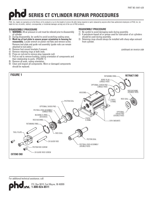
DISASSEMBLY PROCEDURE1)WARNING: All air pressure in unit must be relieved prior to disassemblyof cylinder.2)During disassembly, be careful to avoid scratching sealing areas.3)Mark top of tool plate to ensure proper orientation to housing forreassembly. Locate wrench on piston rod flats and remove screw.Remove tool plate and guide rod assembly (guide rods can remain attached to tool plate.)4)Remove foot mount brackets if present.5) Remove retaining rings at both ends.6) Press on rod end to remove plug (opposite rod).7) Pull on rod to remove bushing, noting orientation of components andtheir relationship to ports. (FIGURE 1)8) Remove all seals, noting orientation.9) Clean and inspect all components. Worn or damaged componentsshould be replaced.PHD, Inc. makes no warranty as to the fitness of its products or as to the length of service life after being repaired or parts replaced by anyone other than authorized employees of PHD, Inc. be liable for loss of profits, indirect, consequential, or incidental damages arising out of the use of PHD products.REASSEMBLY PROCEDURE1)Be careful to avoid damaging seals during assembly.2) A petroleum-based oil or grease used for lubrication of air cylindersshould be used during assembly.3)Retaining rings should always be installed with sharp edge outwardfrom cylinder.continued on reverse side1)Lubricate o-ring and place into second groove of body. (FIGURE 2)2) For standard units, place bore plug into body and secure withretaining ring.3) For shock pad units, place shock pad at bottom of cylinder grooves,making sure shock pad is flat and cannot slide into bore. Then install bore plug onto shock pad and secure with retaining ring.BUSHING1) Replace and lubricate seals. Care should be taken to ensure properorientation of rod seal and bushing. (FIGURE 3)PISTON1) Lubricate and replace piston seal.PISTON AND ROD TO BODY (single rod units only)1) Lubricate cylinder bore, piston rod, seals, and bushings.2) Lubricate o-ring and place into second groove in body for bushing end.(FIGURE 2)3) Assemble bushing onto rod using a turning motion to work rod sealover rod end. Check for proper orientation.4) Place piston rod assembly into cylinder bore and press bushing ontostatic o-ring seal and secure with retaining ring.PISTON AND ROD TO BODY (double rod units only)1) Lubricate cylinder bore, piston rod, seals, and bushings.2) Lubricate o-ring and place into second groove in body for bushing end.(FIGURE 2)3) Assemble one bushing onto rod using a turning motion to work rodseal over rod end. Check for proper orientation.4) Place piston rod assembly into cylinder bore and press bushing ontostatic o-ring seal and secure with retaining ring.5) Place the other bushing onto rod using a turning motion to work rodseal over rod end. Check for proper orientation.6) Press second bushing static o-ring seal and secure with retaining ring.PART NO: 6441-539SERIES CT CYLINDER REPAIR PROCEDURES (continued)TOOL PLATE TO ROD AND GUIDE RODS1)If used, ensure that foot mount brackets are attached to body prior to attaching the tool plate and guide rod assembly to the piston rod.2) Lubricate guide rod bushings in body (FIGURE 4).3) Apply thread locker to guide rod screws and loosely assemble guide rods to tool plate. Assemble guide rods and tool plate to body (ifrebuilding unit, tool plate and guide rods must be reassembled with the same orientation to body as when originally assembled at factory).4) Apply thread locker to piston rod screw and loosely assemble rod to tool plate.5) With tool plate in retracted position , torque guide rod screws to tool plate per CHART 1. Hand cycle unit to check for free movement. Loosen and re-torque guide rod screws if binding occurs.6) With tool plate in retracted position , torque piston rod screw to tool plate per CHART 1. Loosen and re-torque screw if binding prevents unit from cycling at 20 psi [1.4 bar].BORE SIZE 12/1620/2532/4050/63in-lb 416060130Nm 4.67715GUIDE ROD SCREW TORQUE in-lb 41110300450Nm 4.612.53451PISTON RODSCREW TORQUE CHART 1。
- 1、下载文档前请自行甄别文档内容的完整性,平台不提供额外的编辑、内容补充、找答案等附加服务。
- 2、"仅部分预览"的文档,不可在线预览部分如存在完整性等问题,可反馈申请退款(可完整预览的文档不适用该条件!)。
- 3、如文档侵犯您的权益,请联系客服反馈,我们会尽快为您处理(人工客服工作时间:9:00-18:30)。
超高压气动泵操作说明书
气动液压泵操作手册
最大工作压力=2275bar (33000 psi)
主要部件名称
1- 泵架 2- 出油口(快插母接头) 3- 卸压阀
4- 空气流量调节阀 5- 泵总成 6- 油箱
7- 空气滤清器 8- 气源入口
9- 气动两联件(压力表、压力调节和过滤器) 10- 液压表
超高压气动泵操作说明书
安全须知
始终确保回油阀完全开启,确保开关处于水平关闭状态。
请勿加压未连接装有快插公接头的管线。
压力不能超过压力表读数的90%。
时刻检查最大工作压力。
请勿把压力表最大读数作为最大安全压力值。
若对设备安装或使用有任何疑问,请勿尝试操作设备。
确保使用Tentec提供的设备,且确保设备运转正常
严禁使用非Tentec公司修改或加工的螺栓拉伸设备
随时佩带保护镜和保护手套。
确保施工现场附件人员都意识到正在进行高压作业
确保拉伸器和螺栓之间有足够的螺纹啮合长度,必要时可咨询TENTEC 确保压力值达到稳定时才能靠近已加压的拉伸器
加压时决不要解决泄露问题。
不能超过最大工作压力(参看工具表面数值)
不能超过最大活塞行程(参看工具表面数值)
不要站在正对拉伸器轴线方向,预料外的螺栓失效高度危险
超高压气动泵操作说明书
若对此操作说明有任何疑问,请及时联系TENTEC 公司。
简介
此操作维修保养手册旨在帮助操作者安全有效地使用设备。
预防措施
施工人员连接液压泵和任何螺栓拉伸设备之前,请务必确认:
·液压泵的工作压力应和拉伸工具相匹配
·油箱容积足够拉伸工具所需 ·液压油标号应与拉伸器相匹配
气动马达
海泰斯气动马达简便、高效。
由相对较大活塞驱动较小活塞,从而提供高压流量。
所有海泰斯气动泵钢管结构外观,便于携带。
此系列气动泵可配各种液压表,并配有空气调节器针对具体拉伸工具将泵设定为其所需压力值。
技术参数
海泰斯公司可提供各类压力和流量的气动液压泵,
此操作说明主要介绍拉伸器气动泵。
此标准气动泵最大工作压力为1500bar ,安装了合适的压力表和输出连接。
尺寸-36cm ×38cm ×38cm 重量(无油)-26kg 油箱容积---9L
液压活塞直径---6.35mm
液压活塞面积---31.67mm
2
每行程排量---999.6 mm
2
建议用油
粘度级别 ISO 10级,32级和68级 壳牌万利得10#润滑油
耗气量
当压力表盘读数从零到所需压力值时,气源压力为100PSI 时耗气量大概是28ft 3/Min.若减少气源压力,增加液压压力,耗气量将随流量成比例减少。
若对此操作说明有任何疑问,请及时联系
超高压气动泵操作说明书
TENTEC 公司
简介
此操作维修保养手册旨在帮助操作者安全有效地使用设备。
预防措施
施工人员连接液压泵和任何螺栓拉伸设备之前,请务必确认:
·液压泵的工作压力应和拉伸工具相匹配
·油箱容积足够拉伸工具所需 ·液压油标号应与拉伸器相匹配
气动马达
海泰斯气动马达简便、高效。
由相对较大活塞驱动较小活塞,从而提供高压流量。
所有海泰斯气动泵钢管结构外观,便于携带。
此系列气动泵可配各种液压表,并配有空气调压阀。
针对具体拉伸工具将泵设定为其所需压力值。
气压表
连接气源前
超高压气动泵操作说明书
强烈建议先将液压泵的压力设为拉伸器所
需的压力值。
调整空气调压阀来完成此操作。
注意
连接气源前,必须检查:
·卸压阀已完全开启。
·空气流量调节阀处于水平关闭状态。
·油箱有足够油量(液压油级别ISO10,32,68)
设定泵压力值
步骤1
连接泵和主气源。
缓慢打开空气流量调节阀,泵开始运转。
此时没有压力值显示因为回油阀出于开启状态。
泵输出的液压油又流回到油箱。
步骤2
调压前,将空气调压阀旋钮往上提,逆时针旋转,直到压力值降为零,气压降到零时泵停止运行。
步骤3
完全关闭回油阀。
液压表上有少量读数。
步骤4
顺时针旋转空气压力调压阀调节旋钮,缓慢增加气源压力供给。
此时液压表显示读数也随之增加。
当液压表显示已达到所需压力值时,则停止调节空气压力。
步骤5
关闭开关,缓慢打开泄压阀泄压。
压力表读数降为零,将空气压力调节阀调节旋钮往下摁锁紧。
若需要,再次运行泵并设定压力值,检测压力,再次调节。
当确定泵设定的压力值正确时,可进行拉伸操作。
准备工作
超高压气动泵操作说明书
步骤1
逆时针旋转泄压阀确保其处于开启状态。
。
步骤2
确保空气流量调节阀处于关闭状态
步骤3
将气管线与泵的进气口连接。
步骤4
将液压管线与母接头连接。
步骤5
确保油箱内油量足够。
超高压气动泵操作说明书
液压泵的操作
步骤1
顺时针旋转关闭回油阀。
注:不要拧得过紧(若持续拧紧会对回油阀造成损害)
步骤2
缓慢打开空气流量调节阀。
液压表将缓慢显示读数。
步骤3
一旦达到所需压力值则关闭开关。
压力表显示读数保持稳定(在靠近任何加压设备前请确保压力值已保持稳定)
超高压气动泵操作说明书
步骤4
拉伸器紧固完成后,缓慢打开(逆时针旋转)泄压阀泄压。
将压力值缓慢降到0。
注意事项
建议压力值不要超过油压表最大读数的90%。
关闭程序
切断主气源
打开泄压阀
打开空气流量调节阀(排掉系统内空气余压)
关闭空气流量调节阀
将空气过滤器中的水排尽
将油箱加满
妥善存放油泵。