利勃海尔220T参数
琴岛—利勃海尔BYD—220电冰箱的维修

琴岛—利勃海尔BYD—220电冰箱的维修
张春野
【期刊名称】《中外电器》
【年(卷),期】1995(000)002
【总页数】2页(P22-23)
【作者】张春野
【作者单位】无
【正文语种】中文
【中图分类】TM925.207
【相关文献】
1.琴岛—利勃海尔BCD—212A电子切换型电冰箱的控制原理及故障分析 [J], 茅志勇
2.西冷牌利勃海尔BCD—212电冰箱的制冷系统和电路 [J], 郑敏
3.琴岛—利勃海尔的成功之路——青岛电冰箱总厂引进先进技术设备和技术改造的调查报告 [J], 李更舟
4.白云牌BCD-220A电冰箱的制冷系统和电路——电冰箱维修技术参数资料 [J], 华卫平;赵华
5.琴岛海尔BCD-276W型风直冷电冰箱──电气控制原理及维修 [J], 高岩;喻子达
因版权原因,仅展示原文概要,查看原文内容请购买。
利勃海尔挖掘机参数
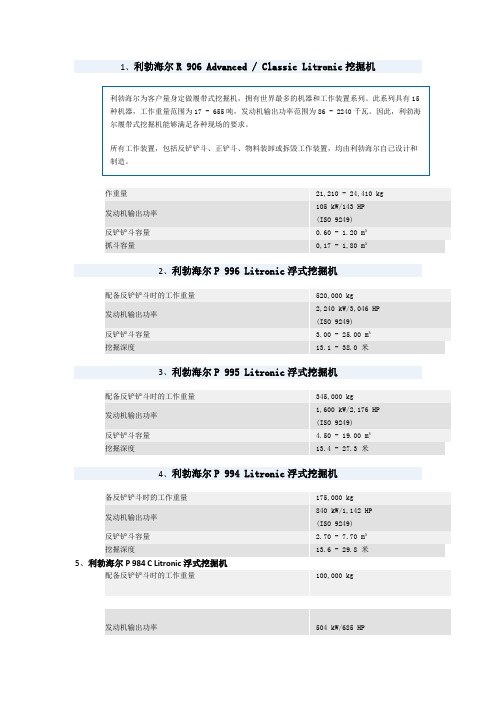
1、利勃海尔R 906 Advanced / Classic Litronic 挖掘机作重量 21,210 - 24,410 kg发动机输出功率 105 kW/143 HP (ISO 9249)反铲铲斗容量 0.60 - 1.20 m³抓斗容量 0,17 - 1,80 m³2、利勃海尔P 996 Litronic 浮式挖掘机配备反铲铲斗时的工作重量 520,000 kg发动机输出功率2,240 kW/3,046 HP(ISO 9249) 反铲铲斗容量 3.00 - 25.00 m³挖掘深度 13.1 - 38.0 米3、利勃海尔P 995 Litronic 浮式挖掘机配备反铲铲斗时的工作重量 345,000 kg发动机输出功率1,600 kW/2,176 HP(ISO 9249) 反铲铲斗容量 4.50 - 19.00 m³挖掘深度 13.4 - 27.3 米4、利勃海尔P 994 Litronic 浮式挖掘机备反铲铲斗时的工作重量 175,000 kg发动机输出功率840 kW/1,142 HP(ISO 9249) 反铲铲斗容量 2.70 - 7.70 m³挖掘深度 13.6 - 29.8 米5、利勃海尔P 984 C Litronic 浮式挖掘机 配备反铲铲斗时的工作重量 100,000 kg 发动机输出功率 504 kW/685 HP(ISO 9249)反铲铲斗容量 2.70 - 7.70 m³挖掘深度8.2 - 16.6 米6、利勃海尔P 974 B Litronic浮式挖掘机配备反铲铲斗时的工作重量68,000 kg发动机输出功率360 kW/490 HP (ISO 9249)反铲铲斗容量 2.60 - 5.60 m³挖掘深度7.5 - 14.3 米7、配备反铲铲斗时的工作重量52,000 kg发动机输出功率270 kW/367 HP (ISO 9249)反铲铲斗容量 2.10 - 4.0 m³挖掘深度8.4 - 13.8 米8、利勃海尔P 954 B Litronic浮式挖掘机配备反铲铲斗时的工作重量42,000 kg发动机输出功率 222 kW/302 HP(ISO 9249)反铲铲斗容量 1.60 - 3.10 m³挖掘深度 7.9 - 11.9 米9、利勃海尔R 9350履带式挖掘机工作重量 302,000 - 310,000 kg发动机输出功率 1,120 kW/1,500 HP (ISO 9249)反铲铲斗容量 18.00 m³ @ 1.8 t/m³正铲斗容量 18.00 m³ @ 1.8 t/m³10、利勃海尔R 9250履带式挖掘机工作重量 249,000 - 253,500 kg发动机输出功率 960 kW/1,287 HP(ISO 9249)反铲铲斗容量 15.00 m³ @ 1.8 t/m³正铲斗容量 15.00 m³ @ 1.8 t/m³ 11利勃海尔R 313 Litronic 挖掘机工作重量 14,200 - 16,700 kg发动机输出功率 74.9 kW/102 HP (ISO 9249)反铲铲斗容量 0.33 - 0.75 m³抓斗容量 0.17 - 0.80 m³12、利勃海尔A 900 C ZW Litronic 轮式挖掘机工作重量 19,650 - 22,000 kg发动机输出功率 105 kW/143 HP(ISO 9249)反铲铲斗容量 0.32 - 0.85 m³抓斗容量 0.10 - 0.48 m³13、利勃海尔R 996 Litronic 大型液压挖掘机工作重量 659.000 - 668.000 kg发动机输出功率 2240 kW/3046 HP (ISO 9249)反铲铲斗容量 33,00 m³ @ 1,8 t/m³正铲斗容量 34,00 m³ @ 1,8 t/m³14、利勃海尔R 995 Litronic 大型液压挖掘机工作重量 439.500 - 448,500 kg发动机输出功率 1600 kW/2176 HP(ISO 9249)反铲铲斗容量 26,50 m³ @ 1,8 t/m³正铲斗容量 26,50 m³ @ 1,8 t/m³15、利勃海尔R 994 B Litronic 大型液压挖掘机工作重量 296.000 - 300.500 kg发动机输出功率 1120 kW/1523 HP (ISO 9249)反铲铲斗容量 18,00 m³ @ 1,8 t/m³正铲斗容量 18,00 m³ @ 1,8 t/m³16、利勃海尔R 994 Litronic 大型液压挖掘机工作重量 229.000 - 226.400 kg发动机输出功率 973 kW/1323 HP(ISO 9249)反铲铲斗容量 13,00 m³ @ 1,8 t/m³正铲斗容量 13,50 m³ @ 1,8 t/m³17、利勃海尔R 984 C Litronic 履带式挖掘机工作重量 118.600 - 125.000 kg发动机输出功率 504 kW/685 HP (ISO 9249)反铲铲斗容量 7,0 m³ @ 1,8 t/m³正铲斗容量 7,0 m³ @ 1,8 t/m³18、利勃海尔R 974 B Litronic 履带式挖掘机工作重量 81 500 - 88 200 kg发动机输出功率 395 kW/537 HP(ISO 9249)反铲铲斗容量 2,20 - 7,00 m³正铲斗容量 4,40 - 7,50 m³抓斗容量1,20 - 2,80 m³19、利勃海尔R 964 B Litronic履带式挖掘机R 964 B Litronic 履带式挖掘机宽敞、舒适的操作员室,以及人机工程学优化工作区域,实现了无疲劳高效操作。
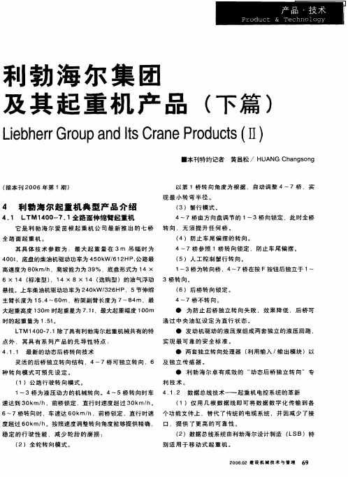
利勃海尔集团及其起重机产品(下篇)
( 6)标 准 辅 助 卷 扬 ( 穿绳 卷 扬 ) 装 在 配 重 架 上 。安
系统 和 起 重 臂 传 感 系统 。通 过 5条 利 勃 海 尔 数 据 总线 系 便 于 穿 绕 起 重 和 变 幅 钢 丝 绳 。
统 ( LSB) 相 互 连 接 。 ( 7)在 工 作场 地 受 限 制 的 情 况 下 可 用 悬 浮 法 装 配 副臂 。
( 2) 全 轮 转 向模 式 。 ( 2)数 据 总 线 系 统 由利 勃 海 尔 设 计 制造 ( SB)特 L
别 适用 于 移动 式起 重机 。
2 0 .2 建 设 机 械 技 术 与 管 理 6 0 60 9
维普资讯
( ) 上 、下 车 电气 系统 包 括 :驾驶 控 制 功 能 、支腿 3
4 1 1 最 新 的 动 态 后 桥 转 向技 术 ..
● 两套独立转 向处理器 ( 利用输入 / 出模块 )以 输
灵 活 的后 桥 独 立 转 向结 构 ,4~7桥 可 独 立 转 向 ,6 及 独 立 传 感 器 。 种 转 向模 式 可 预 先 设 定 。 ( 1)公 路 行 驶 转 向模 式 。 ● 利 勃 海 尔 卓 有 成 效 的 “ 态 后 桥 独 立 转 向 ” 专 动
( 5)人 工 控 制 蟹 行 转 向 。 1 ~3桥 为 转 向 桥 ,4~7桥 在 按 F按 钮 后 独 立于 1 ~
其具 体 技术 参数 为 :最 大起 重 量在 3m 吊幅 时 为
4 0 ,底 盘 的 柴 油机 驱 动功 率 为 4 0 W/ 1 HP 公 路 最 0t 5 k 62 , 高速 度为 8 k h,爬 坡 能 力为 3 % ,底 盘 形 式为 1 0 m/ 9 4X
4 1 3 进 一 步 改 进 伸缩 臂 技 术 .. ( )节 伸缩 臂 总长 6 m 采 用 F 1 0 EM ( 限 元 法 ) 重 有
挖掘机资料
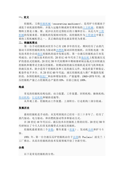
一、定义挖掘机,又称挖掘机械(excavating machinery),是用铲斗挖掘高于或低于承机面的物料,并装入运输车辆或卸至堆料场的土方机械。
挖掘的物料主要是土壤、煤、泥沙以及经过预松后的土壤和岩石。
从近几年工程机械的发展来看,挖掘机的发展相对较快,而挖掘机作为工程建设中最主要的工程机械机型之一,其正确的选型也就显得更为重要。
二、挖掘机简史第一台手动挖掘机问世至今已有130多年的历史,期间经历了由蒸汽驱动斗回转挖掘机到电力驱动和内燃机驱动回转挖掘机、应用机电液一体化技术的全自动液压挖掘机的逐步发展过程。
第一台液压挖掘机由日本发明成功。
由于液压技术的应用,20世纪40年代有了在拖拉机上配装液压反铲的悬挂式挖掘机,20世纪50年代初期和中期相继研制出拖式全回转液压挖掘机和履带式全液压挖掘机。
初期试制的液压挖掘机是采用飞机和机床的液压技术,缺少适用于挖掘机各种工况的液压元件,制造质量不够稳定,配套件也不齐全。
从20世纪60年代起,液压挖掘机进入推广和蓬勃发展阶段,各国挖掘机制造厂和品种增加很快,产量猛增。
1968-1970年间,液压挖掘机产量已占挖掘机总产量的83%,目前已接近100%。
构成常见的挖掘机结构包括,动力装置,工作装置,回转机构,操纵机构,传动机构,行走机构和辅助设施等。
从外观上看,挖掘机由工作装置,上部转台,行走机构三部分组成。
发展历史最初挖掘机是手动的,从发明到现在已经有一百三十多年了,经历了蒸汽驱动,电力驱动,和内燃机驱动等多种驱动方式。
在20世纪40年代以后,液压技术在挖掘机上得到应用,20世纪50年代研制出了今天人们常见的履带式全液压挖掘机。
挖掘机最重要的三个参数:整车重量(质量),发动机功率和铲斗斗容。
1951 年,第一台全液压反铲挖掘机由位于法国的 Poclain( 波克兰 ) 工厂推出,从而在挖掘机的技术发展领域开创了全新空间。
分类以下是常见挖掘机的分类:挖掘机分类一:常见的挖掘机按驱动方式有内燃机驱动挖掘机和电力驱动挖掘机两种。
SAC2200营销培训资料

21
三、 SAC2200产品介绍
制动系统
行车制动器:双回路制动系统,鼓式制动器; 驻车制动器:在第二至第五桥上由蓄压器驱动 作用; 辅助制动器:发动机制动及排气制动; 液力缓速器制动; ABS系统:1、3桥,2、4(5)桥分别采用一 套WABCO 4S/4M ABS系统。
22
三、 SAC2200产品介绍
二、全地面起重机的发展概况
1、国内全地面起重机发展现状 (1)徐重:国内最早研制全地面起重机的厂家,全地面起重 机型谱齐全,国内第一品牌。 (2)中联重科:在全地面起重机的关键技术上(分体式单缸 插销式吊臂伸缩机构、油气悬挂、多轮转向多桥驱动技术 等)取得重大突破,形成了160~500吨的全地面起重机。 (3)三一:在全地面起重机的关键技术研究上取得突破,研 制出五桥QAY220、QAY180、QAY160以及SAC303等型 谱,五桥200吨级的全地面起重机为国内第一。
上车发动机 • BENZ OM906LA 6 缸水冷柴油机 • 额定功率: 170kW/2200rpm • 最大扭矩: 810Nm/12001600rpm
23
三、 SAC2200产品介绍
液压系统
2个主变量泵,控制主卷扬、副卷扬、 变幅、伸缩; 1 个双向变量泵及2个回转马达构成 回转闭式系统 ; 2个辅助油泵做为辅助系统及液压油 散热系统。
15
全路面起重机各吨位段的市场情况(国内情况)
以160T以上全路面起重机为主,200T级产品销量最大;
国产品牌全路面起重机产品开始被用户接受;
大吨位起重机产品需求旺盛;
国内企业加大了全路面起重机产品的开发力度; 国外主要品牌企业通过不同方式加强在中国的竞争力。
16
220t汽车吊参数表

220t汽车吊参数表
参数数值
最大起重量220吨
配重110吨
尺寸(长 * 宽)20m * 7m
高度5m
起重臂长度13m
最大起重高度40m
最大起重半径34m
回转半径 3.5m
起重速度
- 升降速度 1.4m/s
- 回转速度 2.4rpm
行驶速度
- 最高速度35km/h
- 最小转弯半径18m
- 接近角度18°
- 通过角度22°
载重时的挂载高度≤ 11.5m
载重时的挂载半径≤ 4m
发动机型号
- 品牌柴油发动机
- 功率220kW
车速模式汽车/吊车
以上是220t汽车吊的参数表,包括吊车的基本尺寸、重量、起重能力、机械性能和动力性能等。
这款220吨汽车吊的最大起重量为220吨,配重为110吨,整个吊车的尺寸为长20米、宽7米、高5米。
起重臂的长度为13米,最大起重高度为40米,最大起重半径为34米。
吊车底盘可以回转半径为3.5米。
在起重速度方面,升降速度为1.4米/秒,回转速度为2.4rpm。
车辆的行驶速度为35km/h,在最小转弯半径条件下,转弯半径为18米。
吊车的接近角度为18°,通过角度为22°。
载重时的挂载高度不超过11.5米,挂载半径不超过4米。
吊车使用柴油发动机,功率为220kW。
该款吊车具备汽车/吊车两种工作模式,可根据需求进行切换。
以上是220t汽车吊的参数表,该吊车具备较大的起重能力,适用于各种工程施工、装卸货物等重型作业。
世界上最大最小的机械

世界上最大的机械世界上最大的卡车,它的重量为203吨,长47英尺6英寸( 14.5米),高24英尺3英寸( 7.4米)。
LTM11200-9.1在市场上是起重能力最强大的一款伸缩臂起重机,它的伸缩臂长度达到世界之最。
8节主臂能全自动伸缩并锁定在想要达到的长度。
此外,还有多种桁架臂可供选择。
Y型伸缩臂超起装置显著的提高了起重性能。
9桥底盘结合了由利勃海尔研发的独立的、根据速度调节的后轮转向系统及碟式制动确保了行驶过程中安全性和经济性。
最大起重能力:1,200 t at 2.5 m 半径;伸缩臂:18.3 m - 100 m;桁架副臂:24 m - 126 m;底盘发动机/输出功率:利勃海尔,8缸,涡轮柴油发动机,500 kW;起重机发动机/输出功率:利勃海尔,6缸,涡轮柴油发动机,240 kW;传动/转向:18 x 8 x 18;行走速度:75 km/h;工作重量96 t;总配重:202 t。
美国特雷克斯公司日前在北京正式签署了关于CC8800-1双臂履带式起重机的定购协议。
据悉,这台合同金额超过2亿元人民币的CC8800-1“巨无霸”起重机将首先被用在山东省海阳县海阳核电站建造项目工地。
该起重机是目前国际最先进的起重设备,最大起重单位达到3200吨,是迄今为止起重能力最大的移动式起重机,目前在全球范围内实际应用不超过10台。
世界上最大的推土机——推土机由于通常单独作业,不需与矿用卡车等配合,因而其功率就相对于矿用卡车、挖掘机和装载机等功率要小一些,世界上生产特大型推土机的厂商也很少,当前生产超过650kW的推土机的厂商只有Komatsu[小松]和Caterpillar[卡特彼勒]。
下面介绍几个公司的顶级机型,也是到目前为止全球最大的推土机。
Acco的巨型推土机是Acco公司在1980年制造,配备卡特彼勒的V8柴油引擎,功率1300hp,机重183吨,铲刀宽7米,高2.74米,它也使用了卡特开发的“高架链轮驱动”技术。
矿车历史
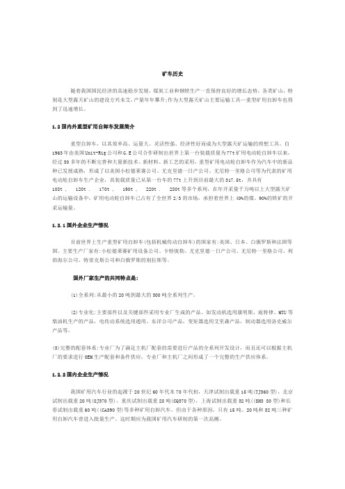
矿车历史随着我国国民经济的高速稳步发展,煤炭工业和钢铁生产一直保持良好的增长态势,各类矿山,特别是大型露天矿山的建设方兴未艾,产量年年攀升;作为大型露天矿山主要运输工具—重型矿用自卸车也得到了迅速增长。
1.2国内外重型矿用自卸车发展简介重型自卸车,以其效率高、运量大、灵活性强、经济性好而成为大型露天矿运输的理想工具。
自1963年由美国Unit-Rig公司和G.E公司合作研制出世界上第一台装载质量为77t矿用电动轮自卸车以来,经过30多年的不断完善和大量新技术、新材料、新工艺的采用,重型矿用电动轮自卸车作为汽车中的新品种已发展成熟,形成了以美国小松德莱赛公司、尤克里德一日产公司、尤尼特一里格公司等为代表的矿用电动轮自卸车生产企业,其装载质量已从第一台车的77t上升到目前最大的317.5t,并具有108t , 120t . 170t , 190t , 220t . 280t等多个系列,在年开采量千万吨以上大型露天矿山的运输设备中,矿用电动轮自卸车己占有了全世界2/3的市场,承担着世界上40%的煤、90%的铁矿的开采运输量。
1.2.1国外企业生产情况目前世界上生产重型矿用自卸车(包括机械传动自卸车)的国家有:美国、日本、白俄罗斯和法国等国。
主要生产厂家有:小松德莱赛矿用设备公司、卡特彼勒、尤克里德一日产公司、尤尼特一里格公司、利勃海尔公司、特雷克斯公司和白俄罗斯的别拉斯等。
国外厂家生产的共同特点是:(1)全系列:从最小的20吨到最大的300吨全系列生产。
(2)专业化:主要部件以及关键部件采用专业厂生成的产品。
如发动机选用康明斯、底特律、MTU等柴油机生产的产品,电传动系统选用通用、东洋公司产品,变矩器选用艾里森产品,制动器选用洛克威尔产品等。
(3)完整的配套体系:专业厂为了满足主机厂配套的需要进行产品的全系列开发设计,而且还可以根据主机厂的要求进行OEM生产配套和备件供应,专业厂和主机厂之间形成了一个完整的生产供应体系。
- 1、下载文档前请自行甄别文档内容的完整性,平台不提供额外的编辑、内容补充、找答案等附加服务。
- 2、"仅部分预览"的文档,不可在线预览部分如存在完整性等问题,可反馈申请退款(可完整预览的文档不适用该条件!)。
- 3、如文档侵犯您的权益,请联系客服反馈,我们会尽快为您处理(人工客服工作时间:9:00-18:30)。
Compact, maneuverable and weight-optimized•Powerful, 6-cylinder Liebherr turbo-charged diesel engine type D846 A7, 370 kW/503 hp, exhaust gas emissions correspond to the directives 97/68/EC Stage 3 and EPA/CARB Tier 3, robust and reliable, modern and electronically-controlled engine management•ZF power shift gear with automated AS-TRONIC control system. ZF intarder fitted directly to the gear unit, 12 forward and 2 reverse gears, automated control, reduced fuel consumption due to a high number of gears•2-stage, robust transfer case with lockable transfer differential,creeping speed 0.78 km/h•Drive 10 x 6, axles 2, 4 and 5 driven•Drive 10 x 8 (optional), axles 2, 4 and 5 driven, axle 1 can be activated for off-road displacement•Weight-optimized, robust, low-maintenance axles, perfect track keeping and lateral stability due to special arrangement of the steering knuckles; maintenance-free axle struts, steel and rubber mounted•Maintenance-free drive shafts; quick and easy fitting due to 70° diagonal toothing•Hydropneumatic ”Niveaumatik” suspension, program-controlled for ”setting crane on outriggers”, ”cranedisplacement with equipment” and "crane displacement on the road", suspension travel +150/-150mm•Lateral force released and maintenance-free suspension rams, piston rods protected against damage by synthetic pipes•Sustained-action brakes:Engine brake as exhaust retarder with Liebherr additional brake system (ZBS), intarder on gear, optional T elma-type eddy current brake •Service brake:All axles fitted with air disc brakes, high braking performance,long maintenance intervals, rapid-change brake liningsModern drive concept•Overall length 15.52 m, carrier length 13.3 m •Large overhang angles of up to 20°•Smallest turning radius of 11.01 m with all-wheel steering •Rear counterweight radius only 4.85 m •60 t total weight (axle load 5 x 12 t)•Choice of 3 tyre sizes14.00R 25 carrier width 3 m 16.00R 25 carrier width 3 m 20.5R 25 carrier width 3.1 mAxles 3, 4 and 5 set up as …active rear-axle steering, 5 steering methods are preselectable by fixed programs (P):P1: On-road steeringAxles 1 and 2 are steered mechanically with hydraulic assistance by the steering wheel. Axles 3, 4 and 5 are steered …actively“speed-dependent, subject to the cramp of the front axles,and over 30 km/h, axles 3 and 4 are set to straight displacement and fixed, from 60 km/h, axle 5 is fixed equally to straight displacement. The change of the steering angle in accordance with the speed, results in a precise and stable driving quality during higher speeds, tyre abrasion is reduced and the maneuverability clearly improved.P2: All-wheel steeringAxles 3, 4 and 5, dependent on the steering angle of axle 1are cramped by means of the steering wheel so that the smallest turning radii can be performed.P3: Crab steeringAxles 3, 4 and 5 are cramped into the same direction as axles 1 and 2 by means of the steering wheel.P4: Steering without swervingAxles 3, 4 and 5 are cramped in accordance with axle 1 so that no swerve out of the rear of the carrier takes place.P5: Independent rear-axle steeringAxles 1 and 2 are cramped by the steering wheel, axles 3, 4and 5 steered independent of the cramp of axles 1 and 2 by momentary-contact buttons, whereby the cramp of axle 3 is adapted to the required situation.•A failure in the rear-axle steering makes it ineffective and the rear axles are set to straight displacement by the centering rams•T wo independent hydraulic circuits with wheel- and engine-driven hydraulic pump, thus maximum safety standard •T wo independent control processors (by existing E/A modules)and diversified sensoriel system•Entire know-how of the …active rear-axle steering“ by LiebherrVariable steering concept with…active rear-axle steering“•Variable support basis outriggers retractedSupport basis 5.5 m x 8.9 m Support basis 8.3 m x 8.9 m•Fix-mounted supporting pads with splash guard •Supporting ram travel of up to 700 mm•Level control of the outriggers, all-automatic push-button crane levelling during the supporting procedure•2 x 9° lateral inclination of crane and crane superstructure •Control panels at either side of the carrier with membrane keyboard and electronic inclination indicator, push-buttons for ENGINE/START/STOP and speed control are illuminated and lockable•Operation of the outrigger system in accordance with accident-prevention legislation•Illumination of the supporting area by 4 incorporated projectorsSetting crane on outriggers –quick, convenient and safe•Modern, comfortable driver’s cab of high functionality and convincing design, corrosion-resistant, sheet steel version,cataphoretic dip-primed, front mounted on rubber shock absorbers, rear cushioned hydraulically, internal sound and heat absorbing panelling•Safety glass all-round, greenish tinted front and side windows for heat absorption, electric window lifters•Arrangement of the control elements and displays according to ergonomical aspects for safe and convenient handling during continuous operation•Digital display and keyboard units interconnected with the functional blocks by data bus technology•Driver’s seat cushioned pneumatically, with pneumatic lumber support, headrest•Steering wheel adjustable in height and inclination •Heatable and electrically adjustable rear mirrors •Safety belts for driver and co-driver•3 windscreen wipers with automatic wipe/wash system and intermittent control•Delayed switch-off of the interior lights •Various racks and stackers •Radio preparationComfortable driver’s cab of high functionality54 t•Crane engine: 4-cylinder Liebherr turbo-charged diesel engine type D934L A6 with 180 kW/245 hp, exhaust gas emissions in accordance with the directives 97/68/EC Stage 3 and EPA/CARB Tier 3, robust and reliable, located opposite the crane cab, thus lower noise emissions, electronic engine management, optimized fuel consumption, stainless steel exhaust gas system•Hydraulic system with 5 axial-piston variable displacement pumps with servo control and capacity regulation,electronically-controlled oil cooler as standard•Highly-efficient noise abatement of the diesel-hydraulic crane drive as standardCrane drive withfield-proven components•Liebherr-built winches (hoist gear 1 and 2) with special grooving, with integrated planetary gears and spring-mounted multi-disc brakes as static brakes•Liebherr-built axial-piston constant-output engine, speciallydesigned for crane operation, exposed successfully to tough fatigue tests•Display of the winch rotation on the LICCON screen •Non-rotating hoist ropeLiebherr winch technology•Counterweight variants 12 t, 22 t, 34 t, 44 t, 54 t and 74 t •Control of ballasting from the crane cab •Quick ballasting by “key-hole” method•Ballasting cylinder permanently mounted to superstructure •Compact counterweight dimensions, e.g. 54-t counterweight of only 3.6-m widthBallasting –in a matter of minutesoviform boom profile•6-section, 60-m-long telescopic boom with rounded, oviform bottom shell for high lateral stability•Optimal utilisation of the telescopic boom due to a multitude of telescoping variants•12.2-m – 22-m-long biparted swing-away jib extendable to 29 m and 36 m•Swing-away jib mountable at 0°, 22.5° and 45°, hydraulic fitting aid, hydraulic ram for continuous variation of the swing-away jib from 0° – 45° (optional)•T elescopic boom extension 7 m, resulting in a 7-m higher attachment point for the swing-away jib•Quick and easy re-reeving of the hoist rope by rope dead end connection•Load hook with rope dead end connection, cylindrical load hook shape for easy displacement by rolling on the groundLifting of loads -precise and safeThe Liebherr mobile cranes are entirely equipped with databus transfer systems. The digital system is the basis for thedata bus. It permits the transfer of a multitude of informationalmost parallel and faultless via one only cable. Liebherr hasdeveloped its own system bus (LSB) which corresponds tothe manifold requirements in respect to all possible mobilecrane operations. All important electrical and electronicalcomponents on the superstructure, such as length sensors,angle sensors, load cells, proximity switches, master switchesand hoist limit switch are equipped with their ownmicroprocessors and communicate via various data busnetworks. The keyboard and display units, the outrigger controlas well as the engine and transmission control on the vehicleare intelligent function blocks and equipped with bus interfaces.A continuous self-test of the sensors during operationguarantees a high functional reliability. The internetworking ofthe LICCON computer system with the system bus establishesentirely new and comprehensive diagnostic facilities in respectto the crane.Data bus techniquerevolutionises thecrane electric system•Reduction of the operating costs due to a modern engineand transmission management (CAN bus system); increasedeconomy due to improved endurance of the individual units•Improved reliability due to a considerably reduced numberof electrical cables and contacts•A continuous self-test of the …intelligent sensors“ guaranteesa maximum of reliability•Comprehensive diagnostic facilities - quick error detection•Self-manufactured bus systems, specially adapted to therequirements of a mobile crane•The data bus technique increases the comfort and safetyduring driving and crane operationThe advantages of thedata bus technique at a glance•Standard application programs: Safe load indicator (LMB),configuration program with configuration picture, operation program with operating picture, telescoping program with telescoping picture, test parameter program, test system;supporting force indication and work area limitation as an optional feature•Setting of the configuration program by convenient interactive functions•Safe and reliable acknowledgement of the configuration set •Representation of all essential data by graphic symbols on the operation picture•With integrated wind force test (optional)•Reliable cut-off device when exceeding the admissible load moments•Load capacity values for any boom intermediate length •Winch indications for precise lifting/lowering of the loadLICCON configuration and operation program•T elescoping by single-stage hydraulic ram with hydraulic driving tenons (patented internal interlocking system)•T elescoping procedure controllable by convenient operator’s guide on the monitor, precise approach of the interlocking positions•T elescopable loads are displayed on the LICCON operating picture•Rapid-cycle telescoping system with …automatic mode“, i.e.all-automatic telescoping to the required boom length •Very compact and light-weight telescoping system, thus increased load capacities, especially with long booms and large radii•Automatic cushioning in end positions during telescoping and retracting for the preservation of the structural membersLICCON-assisted telescoping system11LTM 1220-5.2The LICCON test system•The test system assists the servicing personnel in quickly localizing failures of the crane sensory system without the need of measuring instruments •The service starts on the display screen, troubleshooting becomes a matter of seconds •Occurring errors are indicated by error codes and error descriptions on the display screen •Convenient interactive functions permit the observation of all inputs and outputs of the entire system by different representations on the display screen even during crane operation. It equally visualizes the allocation of the individual sensors and actuators of the system and their functions.The LICCON work area limitation system•It relieves the crane operator, especially in situations where the handling of loads requires his full attention, by controlling the work area limits. Work areas can be restricted by buildings,bridges, roofs, high-tension power lines, pipelines or adjacent cranes. The automatic work area limitation system (optional),can easily be programmed. Four different limitation functions are practicable:• Height limitation of the pulley head • Radius limitation • Slewing angle limitation • Limitation of edgesThe LICCON work planner•The LICCON work planner consists of a software program on CD for planning, simulation and documentation of crane applications on the display screen (optional)•The 2D planner program enables the drawing of buildings,to write texts and to represent a crane model true to scale including the entire motions within a fictional construction site •The work planner permits the preparation of more transparent offers, facilitates the briefing of crane operators and can be run on a Laptop at the construction siteSubject to modifications.PN 172.00.E08.2006Liebherr-Werk Ehingen GmbH Postfach 1361, 89582 Ehingen, Germany ట +49 7391 502-0, Fax +49 7391 502-33 , E-Mail: info.lwe@ Electronic SPS crane control with test system•Control of the winches, slewing gear and the luffing and telescoping motions by the LICCON computer system (PLC control)•Four working motions can be performed independently of one another •Speeds for lifting/lowering, luffing and slewing are pre-selectable in 5 steps •Very short response rates at the activation of crane motions •Hoist gear and slewing gear operate within a "closed oil circuit". This enables very sensitive lifting/lowering of loads,or slewing. Moreover , during lowering of the load, the potential energy generated is not converted into heat but can be re-employed for a second motion. This saves fuel and the oil does not reach as high a temperature as during operation within an open circuit.•Functional test of all essential components by means of the LICCON test systemOn the carrier •Additional heater with engine preheating •Eddy-current brake •Supporting force indicator on the carrier and in the operator’s cab •Rope box •Air-conditioning system •Trailer coupling D12/D19•Radio preparation •Seat heating for driver’s and co-driver’s seat •CD radio set On the crane superstructure •Additional heater with engine preheating •2nd hoist gear •Air-conditioning system •Seat heating •Work area limitation •Aircraft warning light •XENON working projector on base section, electrically adjustable •T ele-diagnostic with installed GSM module •CD radio set •Emergency actuationFurther optional features by request.Optional features contribute to an expension of the application spectrum and increase comfort and safetyLiebherr slewing gear Liebherr slewing gear。