ECE R13H 第1版 第5次修订
ecer13h标准

ecer13h标准
ECER13H标准是欧洲标准化委员会(CEN)制定的一个标准,专门用于评
估汽车内饰材料的挥发性有机化合物的释放。
这个标准主要用于评估汽车内饰材料在高温和高湿度环境下的挥发性有机化合物的释放量,以保护驾驶员和乘客的健康。
ECER13H的标准主要包括以下几点:
1. 测试环境:测试需要在温度为40摄氏度,相对湿度为50%的环境中进行。
2. 测试样品:测试需要使用尺寸为300mm x 300mm的样品,样品表面应平整、无气泡、无划痕。
3. 测试方法:将样品放置在测试环境中,持续加热一定时间(通常为24小时),测量释放的挥发性有机化合物浓度。
4. 结果判定:根据测试结果,将内饰材料分为A、B、C、D四个等级,其
中A级表示释放量最小,对健康影响最小。
通过ECER13H标准的测试,可以判断汽车内饰材料对驾驶员和乘客健康的潜在影响,从而为消费者提供更加安全和健康的汽车内饰材料选择。
ECE R13H 第1版 第2次修订

}Rev.2/Add.12H/Rev.1/Amend.2E/ECE/324E/ECE/TRANS/50511 November 2009AGREEMENTCONCERNING THE ADOPTION OF UNIFORM TECHNICAL PRESCRIPTIONS FOR WHEELED VEHICLES, EQUIPMENT AND PARTS WHICH CAN BE FITTED AND/OR BE USED ON WHEELED VEHICLES AND THE CONDITIONS FOR RECIPROCAL RECOGNITION OF APPROVALS GRANTED ON THE BASIS OFTHESE PRESCRIPTIONS ∗/(Revision 2, including the amendments that entered into force on 16 October 1995)_________Addendum 12H: Regulation No. 13-HRevision 1 - Amendment 2Supplement 7 to the original version of the Regulation: Date of entry into force: 22 July 2009UNIFORM PROVISIONS CONCERNING THE APPROVAL OF PASSENGER CARSWITH REGARD TO BRAKING_________UNITED NATIONS∗/ Former title of the Agreement:Agreement Concerning the Adoption of Uniform Conditions of Approval and Reciprocal Recognition of Approval for Motor Vehicle Equipment and Parts, done at Geneva on 20 March 1958.GE.09-}Rev.2/Add.12H/Rev.1/Amend.2E/ECE/324E/ECE/TRANS/505Regulation No. 13-Hpage 2Insert new paragraphs 2.24. to 2.32., to read:angle" means the angle whose tangent is the wheelbase divided by "2.24. "Ackermansteerthe radius of the turn at a very low speed.2.25. "Electronic Stability Control System" or "ESC System" means a system that has allof the following attributes:2.25.1. That improves vehicle directional stability by at least having the ability toautomatically control individually the braking torques of the left and right wheels oneach axle 1/ to induce a correcting yaw moment based on the evaluation of actualvehicle behaviour in comparison with a determination of vehicle behaviourdemanded by the driver;2.25.2. That is computer controlled with the computer using a closed-loop algorithm to limitvehicle oversteer and to limit vehicle understeer based on the evaluation of actualvehicle behaviour in comparison with a determination of vehicle behaviourdemanded by the driver;2.25.3. That has a means to determine directly the value of the vehicle's yaw rate and toestimate its side-slip or side-slip derivative with respect to time;2.25.4. That has a means to monitor driver steering inputs; and2.25.5. That has an algorithm to determine the need, and a means to modify propulsiontorque, as necessary, to assist the driver in maintaining control of the vehicle.acceleration" means the component of the acceleration vector of a point in 2.26. "Lateralthe vehicle perpendicular to the vehicle x axis (longitudinal) and parallel to the roadplane.2.27. "Oversteer" means a condition in which the vehicle's yaw rate is greater than the yawrate that would occur at the vehicle's speed as a result of the Ackerman steer angle. 2.28. "Side-slip or side-slip angle" means the arctangent of the ratio of the lateral velocityto the longitudinal velocity of the centre of gravity of the vehicle.2.29. "Understeer" means a condition in which the vehicle's yaw rate is less than the yawrate that would occur at the vehicle's speed as a result of the Ackerman steer angle.rate" means the rate of change of the vehicle's heading angle measured in 2.30. "Yawdegrees/second of rotation about a vertical axis through the vehicle's centre ofgravity.1/ An axle group shall be treated as a single axle and dual wheels shall be treated as a single wheel.E/ECE/324}Rev.2/Add.12H/Rev.1/Amend.2E/ECE/TRANS/505Regulation No. 13-Hpage 32.31. "Peak braking coefficient (PBC)": means the measure of tyre to road surface frictionbased on the maximum deceleration of a rolling tyre.space" means an area on which more than one tell-tale, indicator, 2.32. "Commonidentification symbol, or other message may be displayed but not simultaneously.factor" means one-half the track width of a vehicle divided by the 2.33. "Staticstabilityheight of its center of gravity, also expressed as SSF = T/2H, where: T = track width(for vehicles with more than one track width the average is used; for axles with dualwheels, the outer wheels are used when calculating "T") and H = height of the centerof gravity of the vehicle.Insert new paragraphs 4.4.3. and 4.4.4., to read:"4.4.3. In the case of a vehicle complying with the Electronic Stability Control requirements of Annex 9 to this Regulation, the additional letters "ESC" shall be placedimmediately to the right of the letter 'R' mentioned in paragraph 4.4.2.4.4.4. In the case of a vehicle complying with the Vehicle Stability Function requirementsof Annex 21 to Regulation No. 13, the additional letters "VSF" shall be placedimmediately to the right of the letter 'R' mentioned in paragraph 4.4.2."Insert new paragraphs 5.2.24. and 5.2.24.1., to read:"5.2.24. Subject to the requirements of paragraphs 12.2. and 12.3., any vehicle fitted with an ESC system complying with the definition of paragraph 2.25. shall meet theequipment, performance and test requirements contained in Annex 9 to thisRegulation.5.2.24.1. As an alternative to the requirement of paragraph 5.2.24., vehicles of categoriesM1 and N1 with a mass in running order > 1,735 kg may be equipped with a vehiclestability function which includes roll-over control and directional control and meetsthe technical requirements of Annex 21 to Regulation No. 13."Insert new paragraphs 12.2. to 12.3., to read:"12.2. As from 1 November 2011, Contracting Parties applying this Regulation may refuse to grant national or regional type approval if the vehicle type does not meet the requirements of this Regulation as amended by Supplement 7 and is not fitted with anElectronic Stability Control System meeting the requirements of Annex 9 to this Regulation.12.3. As from 1 November 2013, Contracting Parties applying this Regulation may refusefirst national registration of a vehicle which does not meet the requirements of thisRegulation as amended by Supplement 7 and is not fitted with an Electronic StabilityControl System meeting the requirements of Annex 9 to this Regulation."E/ECE/324E/ECE/TRANS/505} Rev.2/Add.12H/Rev.1/Amend.2 Regulation No. 13-Hpage 4Annex 1 Insert a new item 21, to read:"21The vehicle is equipped with an ESC system:........................................... Yes/No If yes:The ESC system has been tested according to and fulfilsthe requirements of Annex 9...................................................................... Yes/No or: The vehicle stability function has been tested according toand fulfils the requirements of Annex 21 to Regulation No. 13................ Yes/No" Items 21 to 30 (former), renumber as items 22 to 31. Annex 2, model "A" and the accompanying text, amend to read:"a= 8mm. min.The above approval mark ... in its original form. The additional marking "ESC"indicates that the vehicle meets the Electronic Stability Control requirements of Annex 9 to this Regulation." 13HRESC-002439 ¯R a/3E/ECE/324}Rev.2/Add.12H/Rev.1/Amend.2E/ECE/TRANS/505Regulation No. 13-Hpage 5Insert a new Annex 9, to read (see next pages):"Annex 9ELECTRONIC STABILITY CONTROL SYSTEMSREQUIREMENTS1. GENERALVehicles equipped with an ESC system shall meet the functional requirementsspecified in paragraph 2. and the performance requirements in paragraph 3. under thetest procedures specified in paragraph 4. and under the test conditions specified inparagraph 5. of this annex.2. FUNCTIONALREQUIREMENTSEach vehicle to which this annex applies shall be equipped with an electronicstability control system that:2.1. Is capable of applying braking torques individually to all four wheels 1/ and has acontrol algorithm that utilizes this capability;2.2. Is operational over the full speed range of the vehicle, during all phases of drivingincluding acceleration, coasting, and deceleration (including braking), except:2.2.1. When the driver has disabled ESC;2.2.2. When the vehicle speed is below 20 km/h;2.2.3. While the initial start-up self test and plausibility checks are completed, not toexceed 2 minutes when driven under the conditions of paragraph 5.10.2.;2.2.4. When the vehicle is being driven in reverse.2.3. Remains capable of activation even if the antilock braking system or traction controlsystem is also activated.REQUIREMENTS3. PERFORMANCEDuring each test performed under the test conditions of paragraph 4. and the testprocedure of paragraph 5.9., the vehicle with the ESC system engaged shall satisfythe directional stability criteria of paragraphs 3.1. and 3.2., and it shall satisfy theresponsiveness criterion of paragraph 3.3. during each of those tests conducted with a1/ An axle group shall be treated as a single axle and dual wheels shall be treated as a single wheel.E/ECE/324}Rev.2/Add.12H/Rev.1/Amend.2E/ECE/TRANS/505Regulation No. 13-Hpage 6commanded steering wheel 2/ angle of 5A or greater but limited as perparagraph 5.9.4., where A is the steering wheel angle computed in paragraph 5.6.1.Where a vehicle has been physically tested in accordance with paragraph 4., thecompliance of versions or variants of that same vehicle type may be demonstrated bya computer simulation, which respects the test conditions of paragraph 4. and the testprocedure of paragraph 5.9. The use of the simulator is defined in Appendix 1 to thisannex.3.1. The yaw rate measured 1 second after completion of the Sine with Dwell steeringinput (time T0 + 1 in Figure 1) shall not exceed 35 percent of the first peak value ofyaw rate recorded after the steering wheel angle changes sign (between first andψ&in Figure 1) during the same test run.second peaks) (PeakFigure 1. Steering wheel position and yaw velocity information used to assess lateral stability.2/ The text in this annex assumes that the vehicle steering is controlled by means of a steering wheel. Vehicles using other types of steering control may also be approved to this annex provided the manufacturer is able to demonstrate to the technical service that the performance requirements of this annex can be met using equivalent steering inputs to the steering inputs stipulated under paragraph 5. of this annex.E/ECE/324E/ECE/TRANS/505} Rev.2/Add.12H/Rev.1/Amend.2 Regulation No. 13-Hpage 73.2. The yaw rate measured 1.75 seconds after completion of the Sine with Dwellsteering input shall not exceed 20 percent of the first peak value of yaw rate recordedafter the steering wheel angle changes sign (between first and second peaks) duringthe same test run.3.3. The lateral displacement of the vehicle centre of gravity with respect to its initialstraight path shall be at least 1.83 m for vehicles with a GVM of 3,500 kg or less,and 1.52 m for vehicles with a maximum mass greater than 3,500 kg when computed 1.07 seconds after the Beginning of Steer (BOS). BOS is defined in paragraph 5.11.6.3.3.1.The computation of lateral displacement is performed using double integration withrespect to time of the measurement of lateral acceleration at the vehicle centre ofgravity, as expressed by the formula:An alternative measuring method may be allowed for type approval testing, providedit demonstrates at least an equivalent level of precision as the double integration method.3.3.2. Time t = 0 for the integration operation is the instant of steering initiation, known asthe Beginning of Steer (BOS). BOS is defined in paragraph 5.11.6.3.4. ESC malfunction detectionThe vehicle shall be equipped with a tell-tale that provides a warning to the driver ofthe occurrence of any malfunction that affects the generation or transmission of control or response signals in the vehicle's electronic stability control system. 3.4.1. The ESC malfunction tell-tale:3.4.1.1.Shall be displayed in direct and clear view of the driver, while in the driver's designated seating position with the driver's seat belt fastened; 3.4.1.2.Shall appear perceptually upright to the driver while driving; 3.4.1.3. Shall be identified by the symbol shown for "ESC Malfunction Tell-tale" below orthe text "ESC":3.4.1.4. Shall be yellow or amber in colour; dt a nt Displaceme Lateral .G .C y ∫∫=E/ECE/324}Rev.2/Add.12H/Rev.1/Amend.2E/ECE/TRANS/505Regulation No. 13-Hpage 83.4.1.5. When illuminated must be sufficiently bright to be visible to the driver under bothdaylight and night-time driving conditions, when the driver has adapted to theambient roadway light conditions;3.4.1.6. Except as provided in paragraph 3.4.1.7., the ESC malfunction tell-tale shallilluminate when a malfunction exists and shall remain continuously illuminatedunder the conditions specified in paragraph 3.4. for as long as the malfunction exists,whenever the ignition locking system is in the "On" ("Run") position;3.4.1.7. Except as provided in paragraph 3.4.2., each ESC malfunction tell-tale shall beactivated as a check of lamp function either when the ignition locking system isturned to the "On" ("Run") position when the engine is not running, or when theignition locking system is in a position between "On" ("Run") and "Start" that isdesignated by the manufacturer as a check position;3.4.1.8. Shall extinguish at the next ignition cycle after the malfunction has been corrected inaccordance with paragraph 5.10.4.;3.4.1.9. May also be used to indicate the malfunction of related systems/functions, includingtraction control, trailer stability assist, corner brake control, and other similarfunctions that use throttle and/or individual torque control to operate and sharecommon components with ESC.3.4.2. The ESC malfunction tell-tale need not be activated when a starter interlock is inoperation.3.4.3. The requirement of paragraph 3.4.1.7. does not apply to tell-tales shown in acommon space.3.4.4. The manufacturer may use the ESC malfunction tell-tale in a flashing mode toindicate ESC operation.3.5. ESC Off and other system controlsThe manufacturer may include an "ESC Off" control, which shall be illuminatedwhen the vehicle's headlamps are activated, and which has a purpose to place theESC system in a mode in which it will no longer satisfy the performancerequirements of paragraphs 3., 3.1., 3.2. and 3.3. Manufacturers may also providecontrols for other systems that have an ancillary effect upon ESC operation. Controlsof either kind that place the ESC system in a mode in which it may no longer satisfythe performance requirements of paragraphs 3., 3.1., 3.2. and 3.3. are permitted, providedthat the system also meets the requirements of paragraphs 3.5.1., 3.5.2. and 3.5.3.3.5.1. The vehicle's ESC system shall always return to the manufacturer's original defaultmode that satisfies the requirements of paragraphs 2. and 3. at the initiation of eachnew ignition cycle, regardless of what mode the driver had previously selected.E/ECE/324}Rev.2/Add.12H/Rev.1/Amend.2E/ECE/TRANS/505Regulation No. 13-Hpage 9However, the vehicle's ESC system need not return to a mode that satisfies therequirements of paragraphs 3. through 3.3. at the initiation of each new ignition cycle if: 3.5.1.1. The vehicle is in a four-wheel drive configuration which has the effect of locking thedrive gears at the front and rear axles together and providing an additional gearreduction between the engine speed and vehicle speed of at least 1.6, selected by thedriver for low-speed, off-road driving; or3.5.1.2. The vehicle is in a four-wheel drive configuration selected by the driver that isdesigned for operation at higher speeds on snow-, sand-, or dirt-packed roads andthat has the effect of locking the drive gears at the front and rear axles together,provided that in this mode the vehicle meets the stability performance requirementsof paragraphs 3.1. and 3.2. under the test conditions specified in paragraph 4.However, if the system has more than one ESC mode that satisfies the requirementsof paragraphs 3.1. and 3.2. within the drive configuration selected for the previousignition cycle, the ESC shall return to the manufacturer's original default ESC modefor that drive configuration at the initiation of each new ignition cycle.3.5.2. A control, whose only purpose is to place the ESC system in a mode in which it willno longer satisfy the performance requirements of paragraphs 3., 3.1., 3.2. and 3.3.,shall be identified by the symbol shown for "ESC Off" below or the text "ESC OFF".3.5.3. A control for an ESC system whose purpose is to place the ESC system in differentmodes, at least one of which may no longer satisfy the performance requirements ofparagraphs 3., 3.1., 3.2., and 3.3., shall be identified by the symbol below with thetext "OFF" adjacent to the control position for this mode.]Alternatively, in the case where the ESC system mode is controlled by a multi-functional control, the driver display shall identify clearly to the driver the controlposition for this mode using either the symbol in paragraph 3.5.2. or the text"ESC OFF".3.5.4. A control for another system that has the ancillary effect of placing the ESC systemin a mode in which it no longer satisfies the performance requirements ofparagraphs 3., 3.1., 3.2. and 3.3. need not be identified by the "ESC Off" symbol ofparagraph 3.5.2.E/ECE/324}Rev.2/Add.12H/Rev.1/Amend.2E/ECE/TRANS/505Regulation No. 13-Hpage 103.6. ESC OFF tell-taleIf the manufacturer elects to install a control to turn off or reduce the performance ofthe ESC system under paragraph 3.5., the tell-tale requirements of paragraphs 3.6.1.to 3.6.4. shall be met in order to alert the driver to the inhibited or reduced state ofESC system functionality. This requirement does not apply for the driver-selectedmode referred to in paragraph 3.5.1.2.3.6.1. The vehicle manufacturer shall provide a tell-tale indicating that the vehicle has beenput into a mode that renders it unable to satisfy the requirements of paragraphs 3.,3.1., 3.2. and 3.3., if such a mode is provided.3.6.2. The "ESC Off" tell-tale:3.6.2.1. Shall be displayed in direct and clear view of the driver while in the driver'sdesignated seating position with the driver's seat belt fastened;3.6.2.2. Shall appear perceptually upright to the driver while driving;3.6.2.3. Shall be identified by the symbol shown for "ESC Off" below or the text"ESC OFF";orShall be identified with the English word "OFF" adjacent to either the controlreferred to in paragraph 3.5.2. or 3.5.3. or the illuminated malfunction tell-tale;3.6.2.4. Shall be yellow or amber in colour;3.6.2.5. When illuminated, shall be sufficiently bright to be visible to the driver under bothdaylight and night time driving conditions, when the driver has adapted to theambient roadway light conditions;3.6.2.6. Shall remain continuously illuminated for as long as the ESC is in a mode thatrenders it unable to satisfy the requirements of paragraphs 3., 3.1., 3.2. and 3.3;3.6.2.7. Except as provided in paragraphs 3.6.3. and 3.6.4. each "ESC Off" tell-tale shall beactivated as a check of lamp function either when the ignition locking system isturned to the "On" ("Run") position when the engine is not running, or when theignition locking system is in a position between "On" ("Run") and "Start" that isdesignated by the manufacturer as a check position.3.6.2.8. Shall extinguish after the ESC system has been returned to the manufacturer’soriginal default mode.Regulation No. 13-Hpage 113.6.3. The "ESC Off" telltale need not be activated when a starter interlock is in operation. 3.6.4. The requirement of paragraph 3.6.2.7. of this annex does not apply to tell-talesshown in a common space.3.6.5. The manufacturer may use the ״ESC Off" telltale to indicate an ESC level of functionother than the manufacturer’s original default mode even if the vehicle would meetparagraphs 3., 3.1., 3.2. and 3.3. of this annex at that level of ESC function.3.7. ESC system technical documentationFurther to the requirements defined in Annex 8 to this Regulation the documentationpackage shall, as confirmation that the vehicle is equipped with an ESC system thatmeets the definition of an "ESC System" as in paragraph 2.25. to this Regulation,include the vehicle manufacturer's documentation as specified in paragraphs 3.7.1.to 3.7.4. below.3.7.1. System diagram identifying all ESC system hardware. The diagram shall identifythose components that are used to generate brake torques at each wheel, determinevehicle yaw rate, estimated side-slip or the side-slip derivative and driver steeringinputs.3.7.2. A brief written explanation sufficient to describe the ESC system's basic operationalcharacteristics. This explanation shall include the outline description of the system'scapability to apply braking torques at each wheel and how the system modifiespropulsion torque during ESC system activation, and show that the vehicle yaw rateis directly determined even under the conditions where no wheel speed informationis available. The explanation shall also specify the vehicle speed range and thedriving phases (acceleration, deceleration, coasting, during activation of the ABS ortraction control) under which the ESC system can activate.diagram. This diagram supports the explanation provided under 3.7.3. Logicparagraph 3.7.2.information. An outline description of the pertinent inputs to the 3.7.4. Understeercomputer that control ESC system hardware and how they are used to limit vehicleundersteer.CONDITIONS4. TESTconditions4.1. Ambient4.1.1. The ambient temperature is between 0 °C and 45 °C.4.1.2. The maximum wind speed is no greater than 10 m/s for vehicles with SSF > 1.25,and 5 m/s for vehicles with SSF ≤ 1.25.page 12testsurface4.2. Road4.2.1. Tests are conducted on a dry, uniform, solid-paved surface. Surfaces withirregularities and undulations, such as dips and large cracks, are unsuitable.4.2.2. The road test surface has a nominal 3/ peak braking coefficient (PBC) of 0.9, unlessotherwise specified, when measured using either:4.2.2.1. The American Society for Testing and Materials (ASTM) E1136 standard referencetest tyre, in accordance with ASTM Method E1337-90, at a speed of 40 mph; or4.2.2.2. The k-test method specified in Appendix 2 to Annex 6 of this Regulation.4.2.3. The test surface has a consistent slope between level and 1 per cent.conditions4.3. Vehicle4.3.1. The ESC system is enabled for all testing.mass. The vehicle is loaded with the fuel tank filled to at least 90 per cent of 4.3.2. Vehiclecapacity, and a total interior load of 168 kg comprised of the test driver,approximately 59 kg of test equipment (automated steering machine, data acquisitionsystem and the power supply for the steering machine), and ballast as required tomake up for any shortfall in the weight of test drivers and test equipment. Whererequired, ballast shall be placed on the floor behind the passenger front seat or ifnecessary in the front passenger foot well area. All ballast shall be secured in a waythat prevents it from becoming dislodged during testing.4.3.3. Tyres. The tyres are inflated to the vehicle manufacturer's recommended coldinflation pressure(s) e.g. as specified on the vehicle's placard or the tyre inflationpressure label. Tubes may be installed to prevent tyre de-beading.4.3.4. Outriggers. Outriggers may be used for testing if deemed necessary for test drivers'safety. In this case, the following applies for vehicles with a Static Stability Factor(SSF) ≤ 1.25:4.3.4.1. Vehicles with a mass in running order under 1,588 kg shall be equipped with"lightweight" outriggers. Lightweight outriggers shall be designed with a maximummass of 27 kg and a maximum roll moment of inertia of 27 kg·m2.4.3.4.2. Vehicles with a mass in running order between 1,588 kg and 2,722 kg shall beequipped with "standard" outriggers. Standard outriggers shall be designed with amaximum mass of 32 kg and a maximum roll moment of inertia of 35.9 kg·m2.3/The "nominal" value is understood as being the theoretical target value.Regulation No. 13-Hpage 134.3.4.3. Vehicles with a mass in running order equal to or greater than 2,722 kg shall beequipped with "heavy" outriggers. Heavy outriggers shall be designed with amaximum mass of 39 kg and a maximum roll moment of inertia of 40.7 kg·m2.4.3.5. Automatedmachine. A steering robot programmed to execute the required steeringsteering pattern shall be used in paragraphs 5.5.2., 5.5.3., 5.6. and 5.9. The steeringmachine shall be capable of supplying steering torques between 40 to 60 Nm. Thesteering machine shall be able to apply these torques when operating with steeringwheel velocities up to 1,200 degrees per second.Procedure5. Test5.1. Inflate the vehicles' tyres to the manufacturer's recommended cold inflationpressure(s) e.g. as provided on the vehicle's placard or the tyre inflation pressurelabel.5.2. Tell-tale bulb check. With the vehicle stationary and the ignition locking system inthe "Lock" or "Off" position, switch the ignition to the "On" ("Run") position or,where applicable, the appropriate position for the lamp check. The ESC malfunctiontell-tale shall be illuminated as a check of lamp function, as specified inparagraph 3.4.1.7., and if equipped, the "ESC Off" tell-tale shall also be illuminatedas a check of lamp function, as specified in paragraph 3.6.2.7. The tell-tale bulbcheck is not required for a tell-tale shown in a common space as specified inparagraphs 3.4.3. and 3.6.4.5.3. "ESC Off" control check. For vehicles equipped with an "ESC Off" control, with thevehicle stationary and the ignition locking system in the "Lock" or "Off" position,switch the ignition locking system to the "On" ("Run") position. Activate the "ESCOff" control and verify that the "ESC Off" tell-tale is illuminated, as specified inparagraph 3.6.2. Turn the ignition locking system to the "Lock" or "Off" position.Again, switch the ignition locking system to the "On" ("Run") position and verifythat the "ESC Off" tell-tale has extinguished indicating that the ESC system has beenrestored as specified in paragraph 3.5.1.5.4. BrakeconditioningCondition the vehicle brakes in the manner described in paragraphs 5.4.1. to 5.4.4. 5.4.1. Ten stops are performed from a speed of 56 km/h, with an average deceleration ofapproximately 0.5g.5.4.2. Immediately following the series of ten 56 km/h stops, three additional stops areperformed from 72 km/h at higher deceleration.5.4.3. When executing the stops in paragraph 5.4.2., sufficient force is applied to the brakepedal to bring the vehicle's antilock braking system (ABS) into operation for amajority of each braking event.。
ECE R13H 第1版 第1次修订
}Rev.2/Add.12H/Rev.1/Amend.1E/ECE/324E/ECE/TRANS/5056 November 2008AGREEMENTCONCERNING THE ADOPTION OF UNIFORM TECHNICAL PRESCRIPTIONS FOR WHEELED VEHICLES, EQUIPMENT AND PARTS WHICH CAN BE FITTED AND/OR BE USED ON WHEELED VEHICLES AND THE CONDITIONS FOR RECIPROCAL RECOGNITION OF APPROVALS GRANTED ON THE BASIS OFTHESE PRESCRIPTIONS /(Revision 2, including the amendments that entered into force on 16 October 1995)_________Addendum 12H: Regulation No. 13-HRevision 1 - Amendment 1Supplement 6 to the original version of the Regulation - Date of entry into force: 15 October 2008UNIFORM PROVISIONS CONCERNING THE APPROVAL OF PASSENGER CARSWITH REGARD TO BRAKING_________UNITED NATIONS∗/ Former title of the Agreement:Agreement Concerning the Adoption of Uniform Conditions of Approval and Reciprocal Recognition of Approval for Motor Vehicle Equipment and Parts, done at Geneva on 20 March 1958.GE.08-E/ECE/324}Rev.2/Add.12H/Rev.1/Amend.1E/ECE/TRANS/505Regulation No. 13-Hpage 2Paragraph 5.2.19.2.1., amend to read:"5.2.19.2.1. A break in the wiring ... ON (activated) position.However, if the parking braking system detects correct clamping of the parkingbrake, the flashing of the red warning signal may be suppressed and the non-flashing red signal shall be used to indicate "parking brake applied".Where actuation of the parking brake is normally indicated by a separate redwarning signal ……."Annex 1Insert a title, to read (including the insertion of a new footnote */):"COMMUNICATION */_____________*/ At the request of (an) applicant(s) for Regulation No. 90 approval, the information shall be provided by the Type Approval Authority as contained in Appendix 1 to this annex. However, this information shall not be provided for purposes other than Regulation No. 90 approvals." Add a new Appendix 1, to read:"Annex 1 – Appendix 1LIST OF VEHICLE DATA FOR THE PURPOSE OF REGULATION No. 90 APPROVALS 1. Description of the vehicle type...................................................................................1.1. Trade name or mark of the vehicle, if available..........................................................1.2. Vehicle category.........................................................................................................1.3. Vehicle type according to Regulation No. 13-H approval...........................................1.4. Models or trade names of vehicles constituting the vehicle type, if available................................................................................................................................................1.5. Manufacturer’s name and address...............................................................................2. Make and type of brake linings...................................................................................2.1. Brake linings tested to all relevant prescriptions of Annex 3 ......................................2.2. Brake linings tested to Annex.....................................................................................3. Minimum mass of vehicle...........................................................................................3.1. Distribution of mass of each axle (maximum value)...................................................}Rev.2/Add.12H/Rev.1/Amend.1E/ECE/324E/ECE/TRANS/505Regulation No. 13-Hpage 34. Maximum mass of vehicle.......................................................................................... 4.1. Distribution of mass of each axle (maximum value)....................................................5. Maximum vehicle speed.............................................................................................6. Tyre and wheel dimensions.........................................................................................7. Brake circuit configuration (e.g. front/rear or diagonal split).......................................8. Declaration of which is the secondary braking system.................................................9. Specifications of brake valves (if applicable).............................................................. 9.1. Adjustment specifications of the load sensing valve....................................................9.2. Setting of pressure valve.............................................................................................10. Designed brake force distribution................................................................................11. Specification of brake................................................................................................. 11.1. Disc brake type (e.g. number of pistons with diameter(s), ventilated or solid disc)................................................................................................................................... 11.2. Drum brake type (e.g. duo servo, with piston size and drum dimensions)....................................................................................................................................................... 11.3. In case of compressed air brake systems, e.g. type and size of chambers, levers, etc....................................................................................................................................12. Master cylinder type and size......................................................................................13. Booster type and size.................................................................................................."-----。
ECE R13H 第1版

}Rev.2/Add.12H/Rev.1E/ECE/324E/ECE/TRANS/50517 January 2008AGREEMENTCONCERNING THE ADOPTION OF UNIFORM TECHNICAL PRESCRIPTIONSFOR WHEELED VEHICLES, EQUIPMENT AND PARTS WHICH CAN BE FITTED AND/OR BE USED ON WHEELED VEHICLES AND THE CONDITIONS FOR RECIPROCAL RECOGNITION OF APPROVALS GRANTED ON THE BASIS OF THESE PRESCRIPTIONS / (Revision 2, including the amendments which entered into force on 16 October 1995)_________Addendum 12H: Regulation No. 13-HRevision 1Incorporating all valid text up to:Corrigendum 1 to the original version of the Regulation, subject of Depositary NotificationC.N.708.1999.TREATIES-1 dated 6 August 1999Corrigendum 2 to the original version of the Regulation, subject of Depositary NotificationC.N.897.2000.TREATIES-1 dated 27 September 2000Corrigendum 3 to the original version of the Regulation, subject of Depositary NotificationC.N.784.2002.TREATIES-1 dated 1 August 2002Corrigendum 4 to the original version of the Regulation, subject of Depositary NotificationC.N.364.2003.TREATIES-1 dated 8 May 2003Supplement 1 to the original version of the Regulation - Date of entry into force: 27 December 2000 Supplement 2 to the original version of the Regulation - Date of entry into force: 20 February 2002 Corrigendum 1 to Supplement 2 to the original version of the Regulation, subject of Depositary NotificationC.N.440.2004.TREATIES-1 dated 13 May 2004Supplement 3 to the original version of the Regulation - Date of entry into force: 4 April 2005Supplement 4 to the original version of the Regulation - Date of entry into force: 11 June 2007Supplement 5 to the original version of the Regulation - Date of entry into force: 10 November 2007 UNIFORM PROVISIONS CONCERNING THE APPROVAL OF PASSENGER CARSWITH REGARD TO BRAKING_________UNITED NATIONS∗/ Former title of the Agreement:Agreement Concerning the Adoption of Uniform Conditions of Approval and Reciprocal Recognition of Approval for Motor Vehicle Equipment and Parts, done at Geneva on 20 March 1958.GE.08-}Rev.2/Add.12H/Rev.1E/ECE/324E/ECE/TRANS/505Regulation No. 13-Hpage 3Regulation No. 13-HUNIFORM PROVISIONS CONCERNING THE APPROVAL OF PASSENGER CARSWITH REGARD TO BRAKINGCONTENTSREGULATION Page1. Scope (5)2. Definitions (5)3. Application for approval (9)4. Approval (9)5. Specifications (11)6. Tests (26)7. Modification of vehicle type or braking systemand extension of approval (26)8. Conformity of production (26)9. Penalties for non-conformity of production (27)10. Production definitely discontinued (27)11. Names and addresses of Technical Servicesresponsible for conducting approval tests,and of Administrative Departments (27)12. Transitional provisions (27)ANNEXESAnnex 1 - Communication concerning the approval or extension or refusal or withdrawal of approval or production definitely discontinued of a vehicle type with regard tobraking pursuant to Regulation No. 13-HAnnex 2 - Arrangements of approval marksE/ECE/324}Rev.2/Add.12H/Rev.1E/ECE/TRANS/505Regulation No. 13-Hpage 4CONTENTS (continued)Annex 3 - Braking tests and performance of braking systemsAppendix - Procedure for monitoring the state of battery changeAnnex 4 - Provisions relating to energy sources and energy storage devices (energy accumulators)Annex 5 - Distribution of braking among the axles of vehiclesAppendix 1 - Wheel-lock sequence test procedureAppendix 2 - Torque wheel test procedureAnnex 6 - Test requirements for vehicles fitted with anti-lock systemsAppendix 1 - Symbols and definitionsAppendix 2 - Utilisation of adhesionAppendix 3 - Performance on differing adhesion surfacesAppendix 4 - Method of selection of the low adhesion surfaceAnnex 7 - Inertia dynamometer test method for brake liningsAnnex 8 - Special requirements to be applied to the safety aspects of complex electronic vehicle control systems}Rev.2/Add.12H/Rev.1E/ECE/324E/ECE/TRANS/505Regulation No. 13-Hpage 51. SCOPE1.1. This Regulation applies to the braking of vehicles of categories M1 and N1 1/.1.2 This Regulation does not cover:1.2.1. vehicles with a design speed not exceeding 25 km/h;1.2.2. vehicles fitted for invalid drivers.2. DEFINITIONSFor the purposes of this Regulation,2.1. "Approval of a vehicle" means the approval of a vehicle type with regard tobraking.2.2. "Vehicle type" means a category of vehicles which do not differ in such essentialrespects as:2.2.1. the maximum mass, as defined in paragraph 2.11. below;2.2.2. the distribution of mass among the axles;2.2.3. the maximum design speed;2.2.4. a different type of braking equipment, with more particular reference to thepresence or otherwise of equipment for braking a trailer or any presence ofelectric braking system;2.2.5. the engine type;2.2.6. the number and ratios of gears;2.2.7. the final drive ratios;2.2.8. the tyre dimensions.1/ This Regulation offers an alternative set of requirements for category N1 vehicles to those contained in Regulation No. 13. Contracting Parties that apply both Regulation No. 13 and this Regulation recognize approvals to either Regulation as equally valid. M1 and N1 categories of vehicles are defined in Annex 7 to the Consolidated Resolution on the Construction of Vehicles (R.E.3) (TRANS/WP.29/78/Rev.1/Amend.2, as last amended by Amend.4).E/ECE/324}Rev.2/Add.12H/Rev.1E/ECE/TRANS/505Regulation No. 13-Hpage 62.3. "Braking equipment" means the combination of parts whose function isprogressively to reduce the speed of a moving vehicle or bring it to a halt, or tokeep it stationary if it is already halted; these functions are specified inparagraph 5.1.2. below. The equipment consists of the control, the transmission,and the brake proper.2.4. "Control" means the part actuated directly by the driver to furnish to thetransmission the energy required for braking or controlling it. This energy may bethe muscular energy of the driver, or energy from another source controlled by thedriver, or a combination of these various kinds of energy.2.5. "Transmission" means the combination of components comprised between thecontrol and the brake and linking them functionally. The transmission may bemechanical, hydraulic, pneumatic, electric or mixed. Where the braking power isderived from or assisted by a source of energy independent of the driver, thereserve of energy in the system is likewise part of the transmission.The transmission is divided into two independent functions: the controltransmission and the energy transmission. Whenever the term "transmission" isused alone in this Regulation, it means both the "control transmission" and the"energy transmission":2.5.1. "Control transmission" means the combination of the components of thetransmission which control the operation of the brakes, including the controlfunction and the necessary reserve(s) of energy;2.5.2. "Energy transmission" means the combination of the components which supply tothe brakes the necessary energy for their function, including the reserve(s) ofenergy necessary for the operation of the brakes.2.6. "Brake" means the part in which the forces opposing the movement of the vehicledevelop. It may be a friction brake (when the forces are generated by frictionbetween two parts of the vehicle moving relatively to one another); an electricalbrake (when the forces are generated by electro-magnetic action between twoparts of the vehicle moving relatively to but not in contact with one another); afluid brake (when the forces are generated by the action of a fluid situatedbetween two parts of the vehicle moving relatively to one another); or an enginebrake (when the forces are derived from an artificial increase in the brakingaction, transmitted to the wheels, of the engine).2.7. "Different types of braking equipment" means equipment which differ in suchessential respects as:2.7.1. components having different characteristics;}Rev.2/Add.12H/Rev.1E/ECE/324E/ECE/TRANS/505Regulation No. 13-Hpage 72.7.2. a component made of materials having different characteristics, or a componentdiffering in shape or size;2.7.3. a different assembly of the components.2.8. "Component of the braking equipment" means one of the individual parts which,when assembled, constitutes the braking equipment.2.9. "Progressive and graduated braking" means braking during which, within thenormal operating range of the device, and during actuation of the brakes (seeparagraph 2.16. below):2.9.1. the driver can at any moment increase or decrease the braking force by acting onthe control;2.9.2. the braking force varies proportionally as the action on the control (monotonicfunction);2.9.3. the braking force can be easily regulated with sufficient precision.2.10. "Laden vehicle" means, except where otherwise stated, a vehicle so laden as toattain its "maximum mass".2.11. "Maximum mass" means the maximum mass stated by the vehicle manufacturerto be technically permissible (this mass may be higher than the "permissiblemaximum mass" laid down by the national administration).2.12. "The distribution of mass among the axles" means the distribution of the effect ofthe gravity on the mass of the vehicle and/or its contents among the axles.2.13. "Wheel/axle load" means the vertical static reaction (force) of the road surface inthe contact area on the wheel/wheels of the axle.2.14. "Maximum stationary wheel/axle load" means the stationary wheel/axle loadachieved under the condition of the laden vehicle.2.15. "Hydraulic braking equipment with stored energy" means a braking equipmentwhere energy is supplied by a hydraulic fluid under pressure, stored in one ormore accumulator(s) fed from one or more pressure pump(s), each fitted with ameans of limiting the pressure to a maximum value. This value shall be specifiedby the manufacturer.2.16. "Actuation" means both application and release of the control.E/ECE/324}Rev.2/Add.12H/Rev.1E/ECE/TRANS/505Regulation No. 13-Hpage 82.17. "Electric regenerative braking" means a braking system which, duringdeceleration, provides for the conversion of vehicle kinetic energy into electricalenergy.2.17.1. "Electric regenerative braking control" means a device which modulates theaction of the electric regenerative braking system;2.17.2. "Electric regenerative braking system of category A" means an electricregenerative braking system which is not part of the service braking system;2.17.3. "Electric regenerative braking system of category B" means an electricregenerative braking system which is part of the service braking system;2.17.4. "Electric state of charge" means the instantaneous ratio of electric quantity ofenergy stored in the traction battery relative to the maximum quantity of electricenergy which could be stored in this battery;2.17.5. "Traction battery" means an assembly of accumulators constituting the storage ofenergy used for powering the traction motor(s) of the vehicle.2.18. "Phased braking" is a means which may be used where two or more sources ofbraking are operated from a common control, whereby one source may be givenpriority by phasing back the other source(s) so as to make increased controlmovement necessary before they begin to be brought into operation.2.19. "Nominal value" definitions for braking reference performance are required to puta value on the transfer function of the braking system, relating output to input forvehicles individually.2.19.1. "Nominal value" is defined as the characteristic which can be demonstrated attype approval and which relates the braking rate of the vehicle on its own to thelevel of the braking input variable.2.20. "Automatically commanded braking" means a function within a complexelectronic control system where actuation of the braking system(s) or brakes ofcertain axles is made for the purpose of generating vehicle retardation with orwithout a direct action of the driver, resulting from the automatic evaluation ofon-board initiated information.2.21. "Selective braking" means a function within a complex electronic control systemwhere actuation of individual brakes is made by automatic means in whichvehicle retardation is secondary to vehicle behaviour modification.2.22. "Braking signal": logic signal indicating brake activation as specified inparagraph 5.2.22.}Rev.2/Add.12H/Rev.1E/ECE/324E/ECE/TRANS/505Regulation No. 13-Hpage 92.23. "Emergency braking signal": logic signal indicating emergency braking asspecified in paragraph 5.2.23.3. APPLICATION FOR APPROVAL3.1. The application for approval of a vehicle type with regard to braking shall besubmitted by the vehicle manufacturer or by his duly accredited representative.3.2. It shall be accompanied by the under-mentioned documents in triplicate and bythe following particulars:3.2.1. a description of the vehicle type with regard to the items specified inparagraph 2.2. above. The numbers and/or symbols identifying the vehicle typeand the engine type shall be specified;3.2.2. a list of the components, duly identified, constituting the braking equipment;3.2.3. a diagram of assembled braking equipment and an indication of the position of itscomponents on the vehicle;3.2.4. detailed drawings of each component to enable it to be easily located andidentified.3.3. A vehicle, representative of the vehicle type to be approved, shall be submitted tothe Technical Service conducting the approval tests.4. APPROVAL4.1. If the vehicle type submitted for approval pursuant to this Regulation meets therequirements of paragraphs 5. and 6. below, approval of that vehicle type shall begranted.4.2. An approval number shall be assigned to each type approved, its first two digitsshall indicate the series of amendments incorporating the most recent majortechnical amendments made to the Regulation at the time of issue of the approval.The same Contracting Party shall not assign the same number to the same vehicletype equipped with another type of braking equipment, or to another vehicle type.4.3. Notice of approval or of refusal of approval of a vehicle type pursuant to thisRegulation shall be communicated to the Parties to the Agreement which applythis Regulation by means of a form conforming to the model in Annex 1 to thisRegulation and of a summary of the information contained in the documentsreferred to in paragraphs 3.2.1. to 3.2.4. above, the drawings supplied by theE/ECE/324}Rev.2/Add.12H/Rev.1E/ECE/TRANS/505Regulation No. 13-Hpage 10applicant for approval being in a format not exceeding A4 (210 x 297 mm), orfolded to that format, and on an appropriate scale.4.4. There shall be affixed, conspicuously and in a readily accessible place specifiedon the approval form, to every vehicle conforming to a vehicle type approvedunder this Regulation, an international approval mark consisting of:4.4.1. a circle surrounding the letter "E" followed by the distinguishing number of thecountry which has granted approval 2/, and of4.4.2. the number of this Regulation, followed by the letter "R", a dash and the approvalnumber to the right of the circle prescribed in paragraph 4.4.1. above.4.5. If the vehicle conforms to a vehicle type approved under one or more otherRegulations, annexed to the Agreement, in the country which has grantedapproval under this Regulation, the symbol prescribed in paragraph 4.4.1. above,need not be repeated; in such a case, the Regulation and approval numbers and theadditional symbols of all the regulations under which approval has been grantedin the country which has granted approval under this Regulation shall be placed invertical columns to the right of the symbol prescribed in paragraph 4.4.1. above.4.6. The approval mark shall be clearly legible and be indelible.4.7. The approval mark shall be placed close to or on the vehicle data plate.4.8. Annex 2 to this Regulation gives examples of arrangements of approval marks.2/ 1 for Germany, 2 for France, 3 for Italy, 4 for the Netherlands, 5 for Sweden, 6 for Belgium, 7 for Hungary, 8 for the Czech Republic, 9 for Spain, 10 for Serbia, 11 for the United Kingdom, 12 for Austria, 13 for Luxembourg, 14 for Switzerland, 15 (vacant), 16 for Norway, 17 for Finland, 18 for Denmark, 19 for Romania, 20 for Poland, 21 for Portugal, 22 for the Russian Federation, 23 for Greece, 24 for Ireland, 25 for Croatia, 26 for Slovenia, 27 for Slovakia, 28 for Belarus, 29 for Estonia, 30 (vacant), 31 for Bosnia and Herzegovina, 32 for Latvia, 33 (vacant), 34 for Bulgaria, 35 (vacant), 36 for Lithuania, 37 for Turkey, 38 (vacant), 39 for Azerbaijan, 40 for The former Yugoslav Republic of Macedonia, 41 (vacant), 42 for the European Community (Approvals are granted by its Member States using their respective ECE symbol), 43 for Japan, 44 (vacant), 45 for Australia, 46 for Ukraine, 47 for South Africa, 48 for New Zealand, 49 for Cyprus, 50 for Malta, 51 for the Republic of Korea, 52 for Malaysia, 53 for Thailand, 54 and 55 (vacant) and 56 for Montenegro. Subsequent numbers shall be assigned to other countries in the chronological order in which they ratify or accede to the Agreement Concerning the Adoption of Uniform Technical Prescriptions for Wheeled Vehicles, Equipment and Parts which can be Fitted and/or be Used on Wheeled Vehicles and the Conditions for Reciprocal Recognition of Approvals Granted on the Basis of these Prescriptions, and the numbers thus assigned shall be communicated by the Secretary-General of the United Nations to the Contracting Parties to the Agreement.page 115. SPECIFICATIONS5.1. General5.1.1. Braking equipment5.1.1.1. The braking equipment shall be so designed, constructed and fitted as to enablethe vehicle in normal use, despite the vibration to which it may be subjected, tocomply with the provisions of this Regulation.5.1.1.2. In particular, the braking equipment shall be so designed, constructed and fitted asto be able to resist the corroding and ageing phenomena to which it is exposed. 5.1.1.3. Brake linings shall not contain asbestos.5.1.1.4. The effectiveness of the braking equipment shall not be adversely affected bymagnetic or electrical fields. (This shall be demonstrated by compliance withRegulation No. 10, 02 series of amendments.)5.1.1.5. A failure detection signal may interrupt momentarily (< 10 ms) the demand signalin the control transmission, provided that the braking performance is thereby notreduced.5.1.2. Functions of the braking equipmentThe braking equipment defined in paragraph 2.3. must fulfil the followingfunctions:5.1.2.1. Service braking systemThe service braking system must make it possible to control the movement of thevehicle and to halt it safely, speedily and effectively, whatever its speed and load,on any up or down gradient. It must be possible to graduate this braking action.The driver must be able to achieve this braking action from his driving seatwithout removing his hands from the steering control.5.1.2.2. Secondary braking systemThe secondary braking system must make it possible by application of the servicebrake control to halt the vehicle within a reasonable distance in the event offailure of the service braking system. It must be possible to graduate this brakingaction. The driver must be able to obtain this braking action from his driving seatwithout removing his hands from the steering control. For the purposes of thesepage 12provisions it is assumed that not more than one failure of the service brakingsystem can occur at one time.5.1.2.3. Parking braking systemThe parking braking system must make it possible to hold the vehicle stationaryon an up or down gradient even in the absence of the driver, the working partsbeing then held in the locked position by a purely mechanical device. The drivermust be able to achieve this braking action from his driving seat.5.1.3. The requirements of Annex 8 shall be applied to the safety aspects of all complexelectronic vehicle control systems which provide or form part of the controltransmission of the braking function included those which utilize the brakingsystem(s) for automatically commanded braking or selective braking.However, systems or functions, which use the braking system as the means ofachieving a higher level objective, are subject to Annex 8 only insofar as theyhave a direct effect on the braking system. If such systems are provided, theymust not be deactivated during type approval testing of the braking system.5.1.4. Provisions for the periodic technical inspection of braking systems5.1.4.1. It shall be possible to assess the wear condition of the components of the servicebrake that are subject to wear e.g. friction linings and drums/discs (in the case ofdrums or discs, wear assessment may not necessarily be carried out at the time ofperiodic technical inspection). The method by which this may be realized isdefined in paragraphs 5.2.11.2. of this Regulation.5.1.4.2. It shall be possible to verify, in a simple way, the correct operational status ofthose complex electronic systems which have control over braking. If specialinformation is needed, this shall be made freely available.5.1.4.2.1. At the time of type approval, the means implemented to protect against simpleunauthorized modification of the operation to the verification means chosen bythe manufacturer (e.g. warning signal) shall be confidentially outlined.Alternatively, this protection requirement is fulfilled when a secondary means ofchecking the correct operational status is available.5.1.4.3. It shall be possible to generate maximum braking forces under static conditions ona rolling road or roller brake tester.5.2. Characteristics of braking systems5.2.1. The set of braking systems with which a vehicle is equipped must satisfy therequirements laid down for service, secondary and parking braking systems.page 135.2.2. The systems providing service, secondary and parking braking may have commoncomponents so long as they fulfil the following conditions:5.2.2.1. there must be at least two controls, independent of each other and readilyaccessible to the driver from his normal driving position. Every brake controlshall be designed such that it returns to the fully off position when released. Thisrequirement shall not apply to a parking brake control when it is mechanicallylocked in an applied position;5.2.2.2. the control of the service braking system must be independent of the control of theparking braking system;5.2.2.3. the effectiveness of the linkage between the control of the service braking systemand the different components of the transmission systems must not be liable todiminish after a certain period of use;5.2.2.4. the parking braking system must be so designed that it can be actuated when thevehicle is in motion. This requirement may be met by the actuation of thevehicle's service braking system, even partially, by means of an auxiliary control;5.2.2.5. without prejudice to the requirements of paragraph 5.1.2.3. of this Regulation, theservice braking system and the parking braking system may use commoncomponents in their transmission(s), provided that in the event of a failure in anypart of the transmission(s) the requirements for secondary braking are stillensured;5.2.2.6. in the event of breakage of any component other than the brakes (as defined inparagraph 2.6. above) and the components referred to in paragraph 5.2.2.10.below, or of any other failure of the service braking system (malfunction, partialor total exhaustion of an energy reserve), that part of the service braking systemwhich is not affected by the failure, must be able to bring the vehicle to a halt inthe conditions prescribed for secondary braking;5.2.2.7. if service braking is ensured by the action of the driver's muscular energy assistedby one or more energy reserves, secondary braking must, in the event of failure ofthat assistance, be capable of being ensured by the driver's muscular energyassisted by the energy reserves, if any, which are unaffected by the failure, theforce applied to the service brake control not exceeding the prescribed maximum;5.2.2.8. if the service braking force and transmission depend exclusively on the use,controlled by the driver, of an energy reserve, there must be at least twocompletely independent energy reserves, each provided with its own transmission,likewise independent; each of them may act on the brakes of only two or morewheels so selected as to be capable of ensuring by themselves the prescribedpage 14degree of secondary braking without endangering the stability of the vehicleduring braking; in addition, each of the aforesaid energy reserves must beequipped with a warning device as defined in paragraph 5.2.14. below;5.2.2.9. if the service braking force and transmission depend exclusively on the use of anenergy reserve, one energy reserve for the transmission is deemed to be sufficient,provided that the prescribed secondary braking is ensured by the action of thedriver's muscular energy acting on the service brake control and the requirementsof paragraph 5.2.5. are met;5.2.2.10. certain parts, such as the pedal and its bearing, the master cylinder and its pistonor pistons, the control valve, the linkage between the pedal and the mastercylinder or the control valve, the brake cylinders and their pistons, and the lever-and-cam assemblies of brakes, shall not be regarded as liable to breakage if theyare amply dimensioned, are readily accessible for maintenance, and exhibit safetyfeatures at least equal to those prescribed for other essential components (such asthe steering linkage) of the vehicle. Any such part as aforesaid whose failurewould make it impossible to brake the vehicle with a degree of effectiveness atleast equal to that prescribed for secondary braking must be made of metal or of amaterial with equivalent characteristics and must not undergo notable distortion innormal operation of the braking systems.5.2.3. The failure of a part of a hydraulic transmission system shall be signalled to thedriver by a device comprising a red tell-tale signal lighting up before or uponapplication of a differential pressure of not more than 15.5 bar between the activeand failed brake equipment, measured at the master cylinder outlet and remaininglit as long as the failure persists and the ignition (start) switch is in the "on" (run)position. However, a device comprising a red tell-tale signal lighting up when thefluid in the reservoir is below a certain level specified by the manufacturer ispermitted. The tell-tale signal must be visible even by daylight; the satisfactorycondition of the signal must be easily verifiable by the driver from the driver'sseat. The failure of a component of the device must not entail total loss of thebraking equipment's effectiveness. Application of the parking brake must also beindicated to the driver. The same tell-tale signal may be used.5.2.4. Where use is made of energy other than the muscular energy of the driver, thereneed not be more than one source of such energy (hydraulic pump, aircompressor, etc.), but the means by which the device constituting that source isdriven must be as safe as practicable.5.2.4.1. In the event of failure in any part of the transmission of a braking system, the feedto the part not affected by the failure must continue to be ensured if required forthe purpose of halting the vehicle with the degree of effectiveness prescribed forsecondary braking. This condition must be met by means of devices which caneasily be actuated when the vehicle is stationary, or by automatic means.。
ECE R13H 第1版 第5次修订

GE.11-AgreementConcerning the Adoption of Uniform Technical Prescriptions forWheeled Vehicles, Equipment and Parts which can be Fitted and/or be Used on Wheeled Vehicles and the Conditions for ReciprocalRecognition of Approvals Granted on the Basis of these Prescriptions * (Revision 2, including the amendments which entered into force on 16 October 1995)Addendum 12H: Regulation No. 13H Revision 1 – Amendment 5Supplement 10 to the original version of the Regulation - Date of entry into force: 9 December 2010Uniform provisions concerning the approval of passenger cars withregard to brakingUNITED NATIONS* Former title of the Agreement: Agreement Concerning the Adoption of Uniform Conditions ofApproval and Reciprocal Recognition of Approval for Motor Vehicle Equipment and Parts, done at Geneva on 20 March 1958.E /ECE/324/Rev.2/Add.12H/Rev.1/Amend.5−E /ECE/TRANS/505/Rev.2/Add.12H/Rev.1/Amend.512 January 2011E/ECE/324/Rev.2/Add.12H/Rev.1/Amend.5E/ECE/TRANS/505/Rev.2/Add.12H/Rev.1/Amend.52Paragraph 5.2.13., the reference to "ISO 9128:1987", amend to read "ISO 9128:2006" Paragraphs 5.2.23. to 5.2.23.2., amend to read:"5.2.23. When a vehicle is equipped with the means to indicate emergency braking, activation and de-activation of the emergency braking signal shall only begenerated by the application of the service braking system when thefollowing conditions are fulfilled6:5.2.23.1. The signal shall not be activated when the vehicle deceleration is below6 m/s² but it may be generated at any deceleration at or above this value, theactual value being defined by the vehicle manufacturer.The signal shall be de-activated at the latest when the deceleration has fallenbelow 2.5 m/s².5.2.23.2. The following conditions may also be used:(a) The signal may be generated from a prediction of the vehicledeceleration resulting from the braking demand respecting theactivation and de-activation thresholds defined in paragraph 5.2.23.1above;or(b) The signal may be activated at a speed above 50 km/h when theantilock system is fully cycling (as defined in paragraph 2 ofAnnex 6).The signal shall be deactivated when the antilock system is no longer fully cycling."。
ece法规r13h解读

ece法规r13h解读
欧洲汽车电子法规R13H解读
欧洲汽车电子法规R13H是欧洲委员会制定的关于车辆电子系统的规定。
该法规旨在确保车辆电子设备的安全和合规性,以保护交通参与者的生命和财产安全。
R13H法规的内容主要涵盖了车辆电子设备的相关要求和测试程序。
其中,测试程序主要包括电磁兼容性测试、电气安全测试和机械强度测试等方面。
对于电磁兼容性测试,R13H法规要求车辆电子设备应具备抗干扰能力,不会因为其他电子设备的干扰而影响其正常功能。
这意味着车辆电子设备在设计和制造过程中需要采取措施,保证其能在不同的电磁环境下正常工作。
电气安全测试是另一个重要的方面。
R13H法规要求车辆电子设备不仅需要满足正常工作的要求,还需要具备安全性能,确保使用过程中不会对车辆或乘坐人员造成危险。
这一测试包括对电子设备的绝缘性能、防电击能力等方面的检验。
此外,R13H法规还强调了对车辆电子设备的机械强度要求。
这意味着车辆电子设备需要具备足够的抗冲击、抗振动、防水、防尘等能力,以担保其在车辆运行时的稳定性和可靠性。
总之,欧洲汽车电子法规R13H的制定旨在确保车辆电子设备的安全和合规性。
遵守这一法规将有助于提高车辆电子系统的可靠性,保障交通参与者的安全。
给予这一法规的重要性,汽车制造商和相关企业应当严格遵守相关要求,并进行必要的测试和认证,以确保车辆电子设备的符合法规标准。
欧洲法规项目与我国标准的对比
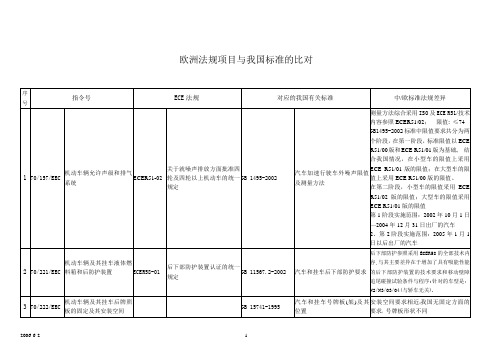
76/761/EEC
机动车辆远光和/或近光前照灯以及这些前照灯装用的白炽灯泡
ECER1-01
ECER2
关于批准发射不对称近光和/或远光并装有R2或HS1类灯丝灯泡的机动车前照灯的统一规定
GB4599-1994
GB 4599-XXXX
汽车前照灯配光性能
《汽车用灯丝灯泡前照灯》
(报批稿)
GB4599-1994为采用标准欧洲光束制定的标准
第1阶段实施范围:2002年10月1日—2004年12月31日出厂的汽车
2、第2阶段实施范围:2005年1月1日以后出厂的汽车
2
70/221/EEC
机动车辆及其挂车液体燃料箱和后防护装置
ECER58-01
后下部防护装置认证的统一规定
GB11567.2-2002
汽车和挂车后下部防护要求
后下部防护参照采用ECER58的全部技术内容,与其主要差异在于增加了具有吸能性能的后下部防护装置的技术要求和移动壁障追尾碰撞试验条件与程序;针对的车型是:N2/N3/O3/O4(与轿车无关).
ECE R112-2001
考虑到快速发展的交通运输对汽车照明的要求,本标准还参考ECE R112的2004版增加有关弯道照明的内容。
ECER5-02
关于批准发射不对称近光和远光机动车封闭型(SB单元)前照灯的统一规定
ECER8-04
关于批准发射不对称近光或远光且装有卤素灯(H1、H2、H3、HB3、HB4、H7、H8、H9、HIR1、HIR2和/或H11)的机动车前照灯的统一规定
GB1495-2002标准中限值要求共分为两个阶段,在第一阶段,标准限值以ECE R51/00版和ECE R51/01版为基础,结合我国情况,在小型车的限值上采用ECE R51/01版的限值;在大型车的限值上采用ECE R51/00版的限值。
ECE系列标准

ECE系列标准ECE系列标准序号代号法规名称1 ECE R1 关于批准发射不对称近光和/或远光并装有R2/或HS1类灯丝灯泡的机动车前照灯的统⼀规定2 ECE R2 关于批准发射不对称近光和/或远光的前照灯⽤⽩炽电灯泡的统⼀规定3 ECE R3 关于批准机动车辆及其挂车回复反射装置的统⼀规定4 ECE R4 关于批准机动车辆(摩托车除外)及其挂车后牌照板照明装置的统⼀规定5 ECE R5 关于批准发射欧洲型不对称近光和/或远光机动车封闭式前照灯(SB) 的统⼀规定6 ECE R6 关于批准机动车及其挂车转向指⽰器的统⼀规定7 ECE R7 关于批准机动车(不含摩托车)及其挂车前后位置(侧边)灯、制动灯和⽰廓灯的统⼀规定8 ECE R8 关于批准发射不对称近光和/或远光并装有卤素灯丝灯泡(H1、H2、H3、HB3、HB4、H7、H8、H9、HIR1、HIR2和/或H11)的机动车前照灯的统⼀规定9 ECE R9 关于就噪声⽅⾯批准L2、L4和L5类车辆的统⼀规定10 ECE R10 关于就电磁兼容性⽅⾯批准车辆的统⼀规定11 ECE R11 关于就门锁和车门保持件⽅⾯批准车辆的统⼀规定12 ECE R12 关于就碰撞中防⽌转向机构伤害驾驶员⽅⾯批准车辆的统⼀规定13 ECE R13 关于就制动⽅⾯批准M类、N类和O类车辆的统⼀规定14 ECE R13--H 关于就制动⽅⾯批准乘⽤车的统⼀规定(欧美⽇协调版)15 ECE R14 关于就安全带固定点⽅⾯批准车辆的统⼀规定16 ECE R15 关于就发动机⽓体污染物排放⽅⾯批准装有点⽕式发动机或压燃式发动机的车辆的统⼀规定--点⽕式发动机的功率测量⽅法---车辆的油耗测量⽅法17 ECE R16 关于:1批准机动车成年乘客⽤安全带和约束系统;2批准装⽤安全带的车辆的统⼀规定18 ECE R17 关于就座椅、座椅固定点和头枕⽅⾯批准车辆的统⼀规定19 ECE R18 关于就防盗⽅⾯批准机动车的统⼀规定20 ECE R19 关于批准机动车前雾灯的统⼀规定21 ECE R20 关于批准发射⾮对称近光和/或远光并装有卤素灯丝灯泡(H4)的机动车前照灯的统⼀规定22 ECE R21 关于就内饰件⽅⾯批准车辆的统⼀规定23 ECE R22 关于批准摩托车轻便摩托车驾驶员及乘客⽤头盔和⾯罩的统⼀规定24 ECE R23 关于批准机动车辆及其挂车的倒车灯的统⼀规定25 ECE R24 关于1.就可见污染物排放⽅⾯批准压燃式(C.I)发动机; 2.就已获得型式批准的C.I.发动机的安装⽅⾯批准机动车; 3.就发动机可见污染物排放⽅⾯批准装⽤C.I.发动机的车辆; 4 .C.I.发动机的功率测量的统⼀规定26 ECE R25 关于批准与车辆座椅⼀体或⾮⼀体的头枕的统⼀规定27 ECE R26 关于就外部凸出物⽅⾯批准车辆的统⼀规定28 ECE R27 关于批准提前三⾓警告牌的统⼀规定29 ECE R28 关于就声响信号⽅⾯批准声报警装置和机动车辆的统⼀规定30 ECE R29 关于就商⽤车辆驾驶室乘员防护⽅⾯批准车辆的统⼀规定31 ECE R30 关于批准机动车及其挂车⽓压轮胎的统⼀规定32 ECE R31 关于批准发射⾮对称近光和/或远光的卤素封闭式(HSB)机动车前照灯的统⼀规定33 ECE R32 关于就追尾碰撞中被撞车辆的结构特性⽅⾯批准车辆的统⼀规定34 ECE R33 关于就正⾯冲撞中被撞的结构特性⽅⾯批准车辆的统⼀规定35 ECE R34 关于就⽕灾预防⽅⾯批准车辆的统⼀规定36 ECE R35 关于就脚控制件的布置⽅⾯批准车辆的统⼀规定37 ECE R36 关于就⼀般结构⽅⾯批准⼤型客车的统⼀规定38 ECE R37 关于批准⽤于已经批准的机动车和挂车灯具中的⽩炽灯的统⼀规定39 ECE R38 关于批准机动车和挂车后雾灯的统⼀规定40 ECE R39 关于就车速表及其安装⽅⾯批准车辆的统⼀规定41 ECE R40 关于就发动机⽓体污染物的排放⽅⾯批准装有点⽕式发动机的摩托车的统⼀规定42 ECE R41 关于就噪声⽅⾯批准摩托车的统⼀规定43 ECE R42 关于就车辆前、后保护装置(保险杠等)批准车辆的统⼀规定44 ECE R43 关于批准安全玻璃材料的统⼀规定45 ECE R44 关于批准机动车⼉童乘客约束装置(⼉童约束系统)的统⼀规定46 ECE R45 关于就前照灯清洗器⽅⾯批准机动车辆和批准前照灯清洗器的统⼀规定47 ECE R46 关于批准后视镜和就后视镜的安装⽅⾯批准机动车辆的统⼀规定48 ECE R47 关于就发动机的⽓体污染物排放⽅⾯批准装有点⽕发动机的轻便摩托车的统⼀规定49 ECE R48 关于就灯光和光信号装置的安装⽅⾯批准车辆的统⼀规定50 ECE R49 关于就发动机污染物排放⽅⾯批准压燃式发动机、天然⽓发动机和燃⽤液化⽯油⽓的点燃式发动机以及装有这些发动机的车辆的统⼀规定51 ECE R50 关于批准轻便摩托车、摩托车及其类似车辆前后位置灯、制动灯、转向信号灯和后牌照板照明装置的统⼀规定52 ECE R51 关于就噪声排放⽅⾯批准四轮及四轮以上机动车的统⼀规定53 ECE R52 关于就⼀般结构⽅⾯批准⼩型公共运输车辆(M2、M3)的统⼀规定54 ECE R53 关于就灯光及光信号装置的安装⽅⾯批准L3类车辆(摩托车)的统⼀规定55 ECE R54 关于批准商⽤车辆及其挂车⽓压轮胎的统⼀规定56 ECE R55 关于批准汽车列车机械联结件的统⼀规定57 ECE R56 关于批准轻便摩托车以及类似车辆前照灯的统⼀规定58 ECE R57 关于批准摩托车以及类似车辆前照灯的统⼀规定59 ECE R58 关于1.批准后下部防护装置;2.就已批准的后下部防护装置的安装⽅⾯批准车辆;3.就后下部防护装置⽅⾯批准车辆的统⼀规定60 ECE R59 关于批准备⽤消声系统的统⼀规定61 ECE R60 关于就驾驶员操纵的控制件,包括控制件、信号装置和指⽰器的识别⽅⾯批准两轮摩托车的统⼀规定62 ECE R61 关于就驾驶室后挡板之前的外部凸出物⽅⾯批准商⽤车的统⼀规定63 ECE R62 关于就防盗⽅⾯批准带有操纵把的机动车的统⼀规定64 ECE R63 关于就噪声⽅⾯批准两轮轻便摩托车的统⼀规定65 ECE R64 关于批准装有应急备⽤车轮/轮胎的车辆的统⼀规定66 ECE R65 关于批准机动车特别警告灯的统⼀规定67 ECE R66 关于就上部结构强度⽅⾯批准⼤型客车的统⼀规定68 ECE R67 关于:1批准在其驱动系统中使⽤液化⽯油⽓的机动车辆特殊装置;2 在这⼀装置的安装⽅⾯批准装⽤使其驱动系统使⽤液化⽯油⽓的特殊装置的车辆的统⼀规定69 ECE R68 关于就最⼤车速的测量⽅⾯批准包括纯电动车辆在内的机动车的统⼀规定70 ECE R69 关于批准低速车辆及其挂车后标志牌的统⼀规定71 ECE R70 关于批准重,长型车辆后标志牌的统⼀规定72 ECE R71 关于就驾驶员视野⽅⾯批准农⽤拖拉机的统⼀规定73 ECE R72 关于批准发射⾮对称近光和远光并装有卤素灯(HS1灯)的摩托车前⼤灯统⼀规定74 ECE R73 关于就侧防护⽅⾯批准货车、挂车和半挂车的统⼀规定75 ECE R74 关于就灯光和光信号装置⽅⾯批准L1类车辆的统⼀规定76 ECE R75 关于批准摩托车和轻便摩托车⽓压轮胎的统⼀规定77 ECE R76 关于批准发射远光和近光的轻便摩托车前照灯的统⼀规定78 ECE R77 关于批准机动车驻车灯的统⼀规定79 ECE R78 关于就制动⽅⾯批准L类车辆的统⼀规定80 ECE R79 关于就转向装置⽅⾯批准车辆的统⼀规定81 ECE R80 关于就座椅及其固定点⽅⾯批准⼤型客车座椅和车辆的统⼀规定82 ECE R81 关于就车把上后视镜的安装⽅⾯批准后视镜及带与不带边⽃的⼆轮机动车的统⼀规定83 ECE R82 关于批准装有卤素灯丝灯泡(HS2)的轻便摩托车前照灯的统⼀规定84 ECE R83 关于根据发动机燃油要求就污染物排放⽅⾯批准车辆的统⼀规定85 ECE R84 关于就油耗测量⽅⾯批准装有内燃机的机动车的统⼀规定86 ECE R85 关于就净功率和最⼤30分钟电传动系功率的测量⽅⾯批准⽤于驱动M和N类机动车辆的内燃机或电传动系的统⼀规定87 ECE R86 关于就灯光和光信号装置的安装⽅⾯批准农林拖拉机的统⼀规定88 ECE R87 换向批准机动车⽩天⾏车灯的统⼀规定89 ECE R88 关于批准摩托车反光轮胎的统⼀规定90 ECE R89 关于1.就最⾼车速限制或其可调车速限制功能⽅⾯批准车辆;2.就已批准型式的最⾼车速限制装置或可调车速限制装置的安装⽅⾯批准车辆;3.批准车速限制装置或可调车速限制装置的统⼀规定91 ECE R90 关于批准机动车辆及其挂车⽤可更替制动衬⽚总成和⿎式制动器衬⽚的统⼀规定92 ECE R91 关于批准机动车及其挂车侧标志灯的统⼀规定93 ECE R92 关于批准摩托车、轻便摩托车和三轮车辆⾮原装可更换排⽓消声系统的统⼀规定94 ECE R93 关于1.批准前下部防护装置;2.就已批准型式的前下部防护装置的安装⽅⾯批准车辆; 3.就前下部防护⽅⾯批准车辆的统⼀规定95 ECE R94 关于就前碰撞中乘员防护⽅⾯批准车辆的统⼀规定96 ECE R95 关于就侧碰撞中乘员防护⽅⾯批准车辆的统⼀规定97 ECE R96 关于就发动机污染物排放⽅⾯批准农林拖拉机和⾮道路机动机械装⽤的压燃式发动机的统⼀规定98 ECE R97 关于批准车辆报警系统和就报警系统⽅⾯批准机动车辆的统⼀规定99 ECE R98 关于批准装⽤⽓体放电光源的机动车前照灯的统⼀规定100 ECE R99 关于批准⽤于已获得型式批准的机动车⽓体放电灯具的⽓体放电光源的统⼀规定101 ECE R100 关于就结构、功能安全性和氢排放的特殊要求⽅⾯批准蓄电池电动车辆的统⼀规定102 ECE R101 关于就CO2排放和油耗的测量⽅⾯批准装⽤内燃机的乘⽤车和就电能消耗量和范围的测量⽅⾯批准装⽤电传动系的M1和N1类车辆的统⼀规定103 ECE R102 关于1.批准紧耦合装置;2.就已批准的紧耦合装置的安装⽅⾯批准车辆的统⼀规定。
- 1、下载文档前请自行甄别文档内容的完整性,平台不提供额外的编辑、内容补充、找答案等附加服务。
- 2、"仅部分预览"的文档,不可在线预览部分如存在完整性等问题,可反馈申请退款(可完整预览的文档不适用该条件!)。
- 3、如文档侵犯您的权益,请联系客服反馈,我们会尽快为您处理(人工客服工作时间:9:00-18:30)。
GE.11-
Agreement
Concerning the Adoption of Uniform Technical Prescriptions for
Wheeled Vehicles, Equipment and Parts which can be Fitted and/or be Used on Wheeled Vehicles and the Conditions for Reciprocal
Recognition of Approvals Granted on the Basis of these Prescriptions * (Revision 2, including the amendments which entered into force on 16 October 1995)
Addendum 12H: Regulation No. 13H Revision 1 – Amendment 5
Supplement 10 to the original version of the Regulation - Date of entry into force: 9 December 2010
Uniform provisions concerning the approval of passenger cars with
regard to braking
UNITED NATIONS
* Former title of the Agreement: Agreement Concerning the Adoption of Uniform Conditions of
Approval and Reciprocal Recognition of Approval for Motor Vehicle Equipment and Parts, done at Geneva on 20 March 1958.
E /ECE/324/Rev.2/Add.12H/Rev.1/Amend.5−E /ECE/TRANS/505/Rev.2/Add.12H/Rev.1/Amend.5
12 January 2011
E/ECE/324/Rev.2/Add.12H/Rev.1/Amend.5
E/ECE/TRANS/505/Rev.2/Add.12H/Rev.1/Amend.5
2Paragraph 5.2.13., the reference to "ISO 9128:1987", amend to read "ISO 9128:2006" Paragraphs 5.2.23. to 5.2.23.2., amend to read:
"5.2.23. When a vehicle is equipped with the means to indicate emergency braking, activation and de-activation of the emergency braking signal shall only be
generated by the application of the service braking system when the
following conditions are fulfilled6:
5.2.23.1. The signal shall not be activated when the vehicle deceleration is below
6 m/s² but it may be generated at any deceleration at or above this value, the
actual value being defined by the vehicle manufacturer.
The signal shall be de-activated at the latest when the deceleration has fallen
below 2.5 m/s².
5.2.23.2. The following conditions may also be used:
(a) The signal may be generated from a prediction of the vehicle
deceleration resulting from the braking demand respecting the
activation and de-activation thresholds defined in paragraph 5.2.23.1
above;
or
(b) The signal may be activated at a speed above 50 km/h when the
antilock system is fully cycling (as defined in paragraph 2 of
Annex 6).
The signal shall be deactivated when the antilock system is no longer fully cycling."。