s3esk_rotary_encoder_interface
LTE_3GPP_36.213-860(中文版)
3GPP
Release 8
3
3GPP TS 36.213 V8.6.0 (2009-03)
Contents
Foreword ...................................................................................................................................................... 5 1 2 3
Internet
Copyright Notification No part may be reproduced except as authorized by written permission. The copyright and the foregoing restriction extend to reproduction in all media.
© 2009, 3GPP Organizational Partners (ARIB, ATIS, CCSA, ETSI, TTA, TTC). All rights reserved. UMTS™ is a Trade Mark of ETSI registered for the benefit of its members 3GPP™ is a Trade Mark of ETSI registered for the benefit of its Members and of the 3GPP Organizational Partners LTE™ is a Trade Mark of ETSI currently being registered for the benefit of i ts Members and of the 3GPP Organizational Partners GSM® and the GSM logo are registered and owned by the GSM Association
S3M4-HSI上网业务配置
All Rights Reserved © Alcatel-Lucent 2010 1x Issue 1x Section 3 · Module 4 · Page 5
Table of Contents [cont.]
Switch to notes view!
3·4·6
配置 · HSI上网业务配置 7342 FTTU EPON · 7342 FTTU EPON R4.6.5x操作维护
Table of Contents
Switch to notes view!
1 Name of Level 1 1.1 Name of Level 2 1.1.1 Name of Level 3 1.1.1.1 Name of Level 4 No Level Text Boxes Symbols (mentioned in Front-Matter Part of Course) Tables Numbered Lists Unnumbered List Presentation of Animation Settings on Slide Master Animation Sequence Complete Text and Graphic Annotations Oversized Screen Snapshots (1) Detail 1 (2) Detail 2 Notes Page only (Standard Notes Text Field Extended) Notes Page only (Active X Word Text Field) Main Colors Splash Pictures (Samples) How to Do It Discover Answer the Questions All Rights Reserved © Alcatel-Lucent 2010 3·4·5 Exercise 配置 · HSI上网业务配置 7342 FTTU EPON · 7342 FTTU EPON R4.6.5x操作维护 Summary Self-Assessment on the Objectives Abbreviations and Acronyms Glossary References End of Module Page 7 8 9 10 11 13 14 15 16 17 18 19 20 21 22 23 24 25 26 27 28 29 30 31 32 33 34 35 37 39 40
ECE R120

}Rev.2/Add.119E/ECE/324E/ECE/TRANS/50521 April 2005AGREEMENTCONCERNING THE ADOPTION OF UNIFORM TECHNICAL PRESCRIPTIONS FOR WHEELED VEHICLES, EQUIPMENT AND PARTS WHICH CAN BE FITTED AND/OR BE USED ON WHEELED VEHICLES AND THE CONDITIONS FOR RECIPROCAL RECOGNITION OF APPROVALS GRANTED ON THE BASIS OFTHESE PRESCRIPTIONS ∗/(Revision 2, including the amendments which entered into force on 16 October 1995)_________Addendum 119: Regulation No. 120Date of entry into force: 6 April 2005UNIFORM PROVISIONS CONCERNING THE APPROVAL OF INTERNAL COMBUSTION ENGINES TO BE INSTALLED IN AGRICULTURAL ANDFORESTRY TRACTORS AND IN NON-ROAD MOBILE MACHINERY, WITHREGARD TO THE MEASUREMENT OF THE NET POWER, NET TORQUEAND SPECIFIC FUEL CONSUMPTION_________UNITED NATIONS∗/Former title of the Agreement:Agreement Concerning the Adoption of Uniform Conditions of Approval and Reciprocal Recognition of Approval for Motor Vehicle Equipment and Parts, done at Geneva on 20 March 1958.}Rev.2/Add.119E/ECE/324E/ECE/TRANS/505Regulation No. 120page 3Regulation No. 120UNIFORM PROVISIONS CONCERNING THE APPROVAL OF INTERNAL COMBUSTION ENGINES TO BE INSTALLED IN AGRICULTURAL AND FORESTRY TRACTORS AND IN NON-ROAD MOBILE MACHINERY, WITH REGARD TO THE MEASUREMENT OF THE NET POWER, NET TORQUE AND SPECIFIC FUEL CONSUMPTIONCONTENTSREGULATION Page1. Scope (5) (5)2. Definitions3. Application for approval (6)4. Approval (6)5. Specifications and tests (8)6. Conformity of production (11)7. Penalties for non-conformity of production (11)8. Modification and extension of approvalof an engine type or engine family (11)9. Production definitely discontinued (12)10. Names and addresses of technical servicesresponsible for conducting approval tests,and of administrative departments (12)ANNEXESAnnex 1: Essential characteristics of the internal combustion engine and general information concerning the conduct of testsAnnex 1 - Appendix 1: Essential characteristics of the engine/parent engineAnnex 1 - Appendix 2: Essential characteristics of the engine familyAnnex 1 - Appendix 3: Essential characteristics of engine type within the familyE/ECE/324}Rev.2/Add.119E/ECE/TRANS/505Regulation No. 120page 4CONTENTS (continued)Annex 2: Communication concerning the approval or extension or refusal or withdrawal of approval or production definitely discontinued of an engine or engine familypursuant to Regulation No. 120Annex 3: Arrangements of approval marksAnnex 4: Method for measuring internal combustion engine net powerAnnex 4 - Appendix: Results of tests for measuring net power engineAnnex 5: Essential characteristics of the engine familyAnnex 6: Checks on conformity of productionAnnex 7: Technical data of reference fuels}Rev.2/Add.119E/ECE/324E/ECE/TRANS/505Regulation No. 120page 51. SCOPE1.1. This Regulation applies to the representation of the curves as a function of enginespeed of the power, torque and specific fuel consumption at full load, indicated bythe manufacturer for internal combustion engines to be used:1.1.1. in category T vehicles1/,1.1.2. in machinery intended and suited to move, or to be moved on the ground, with orwithout road, operated under intermittent or constant speed.1.2. The internal combustion engines belong to one of the following categories:1.2.1. Reciprocating internal combustion engines (positive-ignition or compression-ignition), but excluding free piston engines;1.2.2. Rotary piston engines (positive-ignition or compression-ignition).2. DEFINITIONS2.1. "Approval of an engine" means the approval of an engine type with regard to its netpower measured in accordance with the procedure specified in Annex 4 to thisRegulation;2.2. "Approval of an engine family" means the approval of the members of an enginefamily with regard to their net power in accordance with the procedure specified inAnnexes 5 or 6 to this Regulation;type" means a category of engines which do not differ in such essential 2.3. "Engineengine characteristics as defined in Annex 1 - Appendix 3;family" means a manufacturer's grouping of engines which, through their 2.4. "Enginedesign, fulfil the grouping criteria laid down in Annex 5 to this Regulation;engine" means an engine selected from an engine family in such a way that it 2.5. "Parentcomplies with requirements set out in Annex 5 of this Regulation;power" means the power obtained on a test bench at the end of the crankshaft or 2.6. "Netits equivalent at the corresponding engine speed with the auxiliaries and equipmentlisted in Table 1 of Annex 4 to this Regulation, determined under referenceatmospheric conditions;1/ As described in Annex 7 to the Consolidated Resolution on the Construction of Vehicles (R.E.3) (TRANS/WP.29/78/Rev.1/Amend. 2).E/ECE/324}Rev.2/Add.119E/ECE/TRANS/505Regulation No. 120page 62.7. "Rated net power" means engine net power as declared by the manufacturer at ratedspeed;power" means the maximum value of the net power measured at full 2.8. "Maximumnetengine load;2.9. "Ratedspeed" means the maximum full load speed allowed by the governor, as specified by the manufacturer;2.10. "Maximum net power speed" means the engine speed at which the maximum netpower is obtained, as specified by the manufacturer;2.11. "Maximumspeed" means the engine speed at which the maximum torque istorqueobtained, as specified by the manufacturer;torque" means the maximum value of the net torque measured at full 2.12. "Maximumengine load.3. APPLICATION FOR APPROVAL3.1. The application for approval of an engine type or an engine family with regard to themeasurement of the net power shall be submitted by the manufacturer or by his dulyaccredited representative.3.2. It shall be accompanied by the following documents in triplicate: description of theengine type or engine family comprising all the relevant particulars referred to inAnnex 1 to this Regulation.3.3. An engine representative of the engine type to be approved, or the parent engine, incase of an engine family, fitted with the equipment prescribed in Annex 4 to thisRegulation, shall be submitted to the technical service conducting the approval tests.4. APPROVAL4.1. If the power of the engine submitted for approval pursuant to this Regulation wasmeasured according to the specifications of paragraph 5. below, approval of theengine type or family shall be granted.4.2. An approval number shall be assigned to each engine type or family approved. Itsfirst two digits (at present 00 for the Regulation in its original form) shall indicatethe series of amendments incorporating the most recent major technical amendmentsmade to the Regulation at the time of issue of the approval. The same ContractingParty shall not assign the same number to another engine type or family.}Rev.2/Add.119E/ECE/324E/ECE/TRANS/505Regulation No. 120page 74.3. Notice of approval or of extension or of refusal of approval of an engine type or anengine family pursuant to this Regulation shall be communicated to the Parties to the1958 Agreement applying this Regulation by means of a form conforming to themodel in Annex 2 to this Regulation.4.4. There shall be affixed, conspicuously and in a readily accessible place as specifiedon the approval form, to every engine conforming to an engine type or an enginefamily approved under this Regulation an international approval mark consisting of:4.4.1. A circle surrounding the letter "E" followed by the distinguishing number of thecountry which has granted approval; 2/4.4.2. The number of this Regulation, followed by the letter "R", a dash and the approvalnumber to the right of the circle prescribed in paragraph 4.4.1.Alternatively, instead of affixing these approval marks and symbols to the engine,the manufacturer may decide that engine approved under this Regulation shall beaccompanied by a document giving this information in order to enable the approvalmarks and symbol to be attached to the vehicle.4.5. If the engine conforms to an approved type or family under one or more otherRegulations annexed to the Agreement, in the country which has granted approvalunder this Regulation, the symbol prescribed in paragraph 4.4.1. need not berepeated; in such a case the Regulation and approval numbers and the additionalsymbols of all the Regulations under which approval has been granted underthis Regulation shall be placed in vertical columns to the right of the symbolprescribed in paragraph 4.4.1.2/ 1 for Germany, 2 for France, 3 for Italy, 4 for the Netherlands, 5 for Sweden, 6 for Belgium, 7 for Hungary, 8 for the Czech Republic, 9 for Spain, 10 for Serbia and Montenegro, 11 for the United Kingdom, 12 for Austria, 13 for Luxembourg, 14 for Switzerland, 15 (vacant), 16 for Norway, 17 for Finland, 18 for Denmark, 19 for Romania, 20 for Poland, 21 for Portugal, 22 for the Russian Federation, 23 for Greece, 24 for Ireland, 25 for Croatia, 26 for Slovenia, 27 for Slovakia, 28 for Belarus, 29 for Estonia, 30 (vacant), 31 for Bosnia and Herzegovina, 32 for Latvia, 33 (vacant), 34 for Bulgaria, 35 (vacant), 36 for Lithuania, 37 for Turkey, 38 (vacant), 39 for Azerbaijan, 40 for The former Yugoslav Republic of Macedonia, 41 (vacant), 42 for the European Community (Approvals are granted by its Member States using their respective ECE symbol), 43 for Japan, 44 (vacant), 45 for Australia, 46 for Ukraine, 47 for South Africa, 48 for New Zealand, 49 for Cyprus, 50 for Malta and 51 for the Republic of Korea. Subsequent numbers shall be assigned to other countries in the chronological order in which they ratify or accede to the Agreement Concerning the Adoption of Uniform Technical Prescriptions for Wheeled Vehicles, Equipment and Parts which can be Fitted and/or be Used on Wheeled Vehicles and the Conditions for Reciprocal Recognition of Approvals Granted on the Basis of these Prescriptions, and the numbers thus assigned shall be communicated by the Secretary-General of the United Nations to the Contracting Parties to the Agreement.E/ECE/324}Rev.2/Add.119E/ECE/TRANS/505Regulation No. 120page 84.6. The approval mark shall be placed close to or on the data plate affixed by themanufacturer to the approved type.4.7. Annex 3 to this Regulation gives examples of arrangements of approval marks.4.8. Every engine conforming to an engine type or an engine family approved underthis Regulation must bear, in addition to the approval mark:4.8.1. the trademark or trade name of the manufacturer of the engine;4.8.2. the manufacturer’s engine code.5. SPECIFICATIONS AND TESTS5.1. GeneralThe components liable to affect the power of the engine shall be so designed,constructed and assembled as to enable the engine in normal use, despite thevibrations to which it may be subjected, to comply with the provisions of thisRegulation.5.2. Description of tests for internal combustion engines5.2.1. The net power test shall consist of a run at full throttle for positive-ignition enginesand at fixed full-load fuel injection pump setting for compression-ignition engines,the engine being equipped as specified in Table 1 of Annex 4 to this Regulation.5.2.2. Measurements shall be taken at a sufficient number of engine speeds to definecorrectly the power, torque and specific fuel consumption curves between thelowest and the highest engine speeds recommended by the manufacturer.This range of speeds must include the rotational speeds at which the engineproduces its rated net power, its maximum power and its maximum torque.5.2.3. The fuel used shall be the following:5.2.3.1. For positive-ignition engines fuelled with petrol:The fuel used shall be the reference fuel specified in Annex 7.5.2.3.2. For positive-ignition engines fuelled with LPG:5.2.3.2.1. In the case of an engine with self-adaptive fuelling:}Rev.2/Add.119E/ECE/324E/ECE/TRANS/505Regulation No. 120page 9The fuel used shall be the one available on the market. In any case of dispute thefuel shall be one of the reference fuels specified in Annex 7;5.2.3.2.2. In the case of an engine without self-adaptive fuelling:The fuel used shall be the reference fuel specified in Annex 7 with the lowestC3-content, or5.2.3.2.3. In the case of an engine labelled for one specific fuel composition:The fuel used shall be the fuel for which the engine is labelled.5.2.3.2.4. The fuel used shall be specified in the test report.5.2.3.3. For positive-ignition engines fuelled with natural gas:5.2.3.3.1. In the case of an engine with self-adaptive fuelling:The fuel used shall be the one available on the market. In any case of dispute thefuel shall be one of the references fuels specified in Annex 7;5.2.3.3.2. In the case of an engine without self-adaptive fuelling:The fuel used shall be the one available on the market with the Wobbe Index atleast 52.6 MJm-3 (20 °C, 101.3 kPa). In case of dispute the fuel used shall be thereference fuel GR specified in Annex 7, i.e. the fuel with the highest WobbeIndex, or5.2.3.3.3. In the case of an engine labelled for a specific range of fuels:The fuel used shall be the one available on the market with the Wobbe Index atleast 52.6 MJm-3 (20 °C, 101.3 kPa) if the engine is labeled for the H-range ofgases, or at least 47.2 MJm-3 (20 °C, 101.3 kPa) if the engine is labelled for the L-range of gases. In case of dispute the fuel used shall be the reference fuel GRspecified in Annex 7 if the engine is labelled for the H-range of gases, or thereference fuel G23 if the engine is labelled for the L-range of gases, i.e. the fuelwith the highest Wobbe Index for the relevant range, or 3/3/ "Wobbe Index (lower Wl; or upper Wu)" means the ratio of the corresponding calorific value of a gas per unit volume and the square root of its relative density under the same reference conditions:=ρ/ρW H xgas air gasE/ECE/324}Rev.2/Add.119E/ECE/TRANS/505Regulation No. 120page 105.2.3.3.4. In the case of an engine labelled for one specific fuel composition:The fuel used shall be the fuel for which the engine is labelled.5.2.3.3.5. The fuel used shall be specified in the test report.5.2.3.4. For compression-ignition engines:The fuel used shall be the reference fuel specified in Annex 7.5.2.4. Measurements shall be carried out according to the provisions of Annex 5 to thisRegulation.5.2.5. The test report shall contain the results and all the calculations required to determinethe net power, as listed in the appendix to Annex 4 to this Regulation together withthe characteristics of the engine, as listed in Annex 1 to this Regulation.5.3. Interpretation of ResultsPower5.3.1. NetThe net power declared by the manufacturer for the type of engine (or parent engine)shall be accepted if it does not differ by more than ± 2 per cent for rated net powerand more than ± 4 per cent at the other measurement points on the curve with atolerance of ± 1.5 per cent for engine speed, from the values measured bythe technical service on the engine submitted for testing.5.3.2. RatedspeedThe rated speed declared by the manufacturer shall not deviate by more than 100min-1 from the declared value.consumption5.3.3. FuelThe specific fuel consumption curve declared by the manufacturer for the type ofengine (or parent engine) shall be accepted if it does not differ by more than ± 8 percent at all measurement points from the values measured for the same points bythe technical service on the engine submitted for testing.family5.3.4. EngineIn case of compliance of the parent engine to the conditions in paragraphs 5.3.1. and5.3.2., the acceptance is automatically extended to all the declared curves of thefamily members.}Rev.2/Add.119E/ECE/324E/ECE/TRANS/505Regulation No. 120page 116. CONFORMITY OF PRODUCTIONThe conformity of production procedures shall comply with those set out in theAgreement, Appendix 2 (E/ECE/324-E/ECE/TRANS/505/Rev.2), with the followingrequirements:6.1. Engines approved under this Regulation shall be so manufactured as to conform tothe type approved.6.2. The minimum requirements for conformity of production control procedures setforth in Annex 6 to this Regulation shall be complied with.7. PENALTIES FOR NON-CONFORMITY OF PRODUCTION7.1. The approval granted in respect of an engine type or an engine family pursuant tothis Regulation may be withdrawn if the requirements set forth in paragraph 6.1.above are not met or if an engine or an engine family bearing the approval mark doesnot conform to the type approved.7.2. If a Contracting Party to the 1958 Agreement applying this Regulation withdraws anapproval it has previously granted, it shall forthwith so notify the other ContractingParties applying this Regulation, by means of a communication form conformingto the model in Annex 2 to this Regulation.8. MODIFICATION AND EXTENSION OF APPROVAL OF AN ENGINE TYPEOR ENGINE FAMILY8.1. Every modification of an engine type or an engine family with regard to thecharacteristics in Annex 1, shall be notified to the administrative department whichapproved the engine type or engine family. The department may then either:8.1.1. Consider that the modifications made are unlikely to have any appreciable adverseeffect and that in any case the engine still complies with the requirements; or8.1.2. Require a further test report from the technical service responsible for conducting thetests.8.2. Confirmation or refusal of approval, specifying the alterations shall becommunicated by the procedure specified in paragraph 4.3. above to the Parties tothe Agreement applying this Regulation.8.3. The competent authority issuing the extension of approval shall assign a seriesnumber for such an extension and inform thereof the other Parties to the1958 Agreement applying this Regulation by means of a communication formconforming to the model in Annex 2 to this Regulation.E/ECE/324}Rev.2/Add.119E/ECE/TRANS/505Regulation No. 120page 12DEFINITELY DISCONTINUED9. PRODUCTIONIf the holder of an approval completely ceases to manufacture an engine type or anengine family approved in accordance with this Regulation, he shall so inform theauthority which granted the approval. Upon receiving the relevant communicationthat authority shall inform thereof the other Parties to the 1958 Agreement applyingthis Regulation by means of a communication form conforming to the model inAnnex 2 to this Regulation.10. NAMES AND ADDRESSES OF TECHNICAL SERVICES RESPONSIBLE FORCONDUCTING APPROVAL TESTS, AND OF ADMINISTRATIVEDEPARTMENTSThe Parties to the Agreement which apply this Regulation shall communicate to theUnited Nations Secretariat the names and addresses of the technical servicesresponsible for conducting approval tests, and/or the administrative departmentswhich grant approval, and to which forms certifying approval or extension or refusalof approval, issued in other countries, are to be sent.}Rev.2/Add.119E/ECE/324E/ECE/TRANS/505Regulation No. 120page 13Annex 1Annex 1ESSENTIAL CHARACTERISTICS OF THE INTERNAL COMBUSTION ENGINEAND GENERAL INFORMATION CONCERNING THE CONDUCT OF TESTSParent engine/engine type 1/:......................................................................................... 1. General1.1. Make (name of undertaking):.........................................................................................1.2. Type and commercial description of the parent - and (if applicable) of the familyengine(s) 1/:.................................................................................................................... ........................................................................................................................................ 1.3. Manufacturer's type coding as marked on the engine(s) 1/:........................................... ........................................................................................................................................ 1.4. Specification of machinery to be propelled by the engine 2/:........................................ ........................................................................................................................................ 1.5. Name and address of manufacturer:............................................................................... ........................................................................................................................................ 1.6. Name and address of manufacturer's authorized representative (if any):...................... ........................................................................................................................................ 1.7. Location, coding and method of affixing of the engine identification: ........................................................................................................................................ 1.8. Location and method of affixing of the approval mark:................................................ ........................................................................................................................................plant(s):..................................................................................assembly1.9. Address(es)of ........................................................................................................................................E/ECE/324}Rev.2/Add.119E/ECE/TRANS/505Regulation No. 120page 14Annex 12. Attachments2.1. Essentialcharacteristics of the parent engine(s) (see Appendix 1)................................ ........................................................................................................................................characteristics of the engine family (see Appendix 2)....................................2.2. Essential ........................................................................................................................................of engine types within the family (see Appendix 3)...............2.3. Essentialcharacteristics ........................................................................................................................................3. Characteristics of engine-related parts of the mobile machinery (if applicable)........... ........................................................................................................................................4. Photographs of the parent engine...................................................................................5. List of further attachments:5.1. Appendix 1 / Appendix 2 / Appendix 3 1/5.2. Declared power, torque and specific fuel consumption curves for engine/parent engineand engines within the family 1/5.3. Any further attachments, if any:..................................................................................... ____________________1/ Strike out what does not apply.2/ List the types and models.}Rev.2/Add.119E/ECE/324E/ECE/TRANS/505Regulation No. 120page 15Annex 1 - Appendix 1Annex 1 - Appendix 1ESSENTIAL CHARACTERISTICS OF THE ENGINE / PARENT ENGINE 1/1. DESCRIPTION OF ENGINE1.1. Manufacturer:........................................................................................................1.1.2. Manufacturer's engine code:.................................................................................1.1.3. Working principle: positive-ignition/compression-ignition,four-stroke/two-stroke 1/3/:.................................................................................................................mm 1.4. Bore3/:...............................................................................................................mm 1.5. Stroke1.6. Number, layout and firing order of cylinders:......................................................1.7. Engine capacity 4/:................................................................................................cm3 1.8. Volumetric compression ratio 2/:.........................................................................1.9. Combustion system description:...........................................................................combustionchamber and piston crown:........................................of1.10. Drawing(s)1.11. Minimum cross-sectional area of inlet and outlet ports:.......................................1.12. Cooling system: liquid/air 1/1.12.1. Liquid1.12.1.1. Nature of liquid:....................................................................................................1.12.1.2. Circulating pump(s): yes/no 1/1.12.1.3. Characteristics or make(s) and type(s) (if applicable):......................................... ..............................................................................................................................1.12.1.4. Drive ratio(s) (if applicable):................................................................................E/ECE/324E/ECE/TRANS/505}Rev.2/Add.119 Regulation No. 120 page 16Annex 1 - Appendix 11.12.2. Air1.12.2.1. Blower: yes/no 1/1.12.2.2. Characteristics or make(s) and type(s) (if applicable):......................................... ..............................................................................................................................1.12.2.3. Drive ratio(s) (if applicable):................................................................................1.13. Temperature permitted by the manufacturer1.13.1. Liquid cooling: maximum temperature at outlet:.................................................K1.13.2. Air cooling: reference point:.................................................................................1.13.3. Maximum temperature at reference point:............................................................K1.13.4. Maximum charge air outlet temperature at the inlet inter-cooler (if applicable):..............................................................................................................................K1.13.5. Maximum exhaust temperature at the point in the exhaust pipe(s) adjacent to theouter flange(s) of the exhaust manifold(s):...........................................................K1.13.6. Lubricant temperature: minimum:............................................................K maximum:...........................................................K 1.14. Pressure charger: yes/no 1/1.14.1. Make:....................................................................................................................1.14.2. Type:.....................................................................................................................1.14.3. Description of the system (e.g. max. charge pressure, waste-gate, if applicable):1.14.4. Inter-cooler: yes/no 1/1.15. Intake system: maximum allowable intake depression at rated engine speed and at100 % load:...........................................................................................................kPa1.16. Exhaust system: maximum allowable exhaust back-pressure at rated engine speedand at 100 % load:................................................................................................kPa。
STM32固件库使用手册的中文翻译版
因为该固件库是通用的,并且包括了所有外设的功能,所以应用程序代码的大小和执行速度可能不是最优 的。对大多数应用程序来说,用户可以直接使用之,对于那些在代码大小和执行速度方面有严格要求的应 用程序,该固件库驱动程序可以作为如何设置外设的一份参考资料,根据实际需求对其进行调整。
1.3.1 变量 ................................................................................................................................................ 28 1.3.2 布尔型 ............................................................................................................................................ 28 1.3.3 标志位状态类型 ........................................................................................................................... 29 1.3.4 功能状态类型 .............................................................................................................
亚马逊 AWS CloudFormation 用户指南
AWS CloudFormation 用户指南
欢迎 ......................................................................................................................................................... 1 介绍 ......................................................................................................................................................... 2 堆栈 ........................................................................................................................................................ 2 模板 ......................................................................................................................................................... 3 参数 ......................................................................................................................................................... 5 映像 ......................................................................................................................................................... 6 条件 ......................................................................................................................................................... 7 伪参数 ..................................................................................................................................................... 8 资源 ......................................................................................................................................................... 8 资源属性 .................................................................................................................................................. 9 参考 ......................................................................................................................................................... 9 固有功能 ................................................................................................................................................ 10 输出 ....................................................................................................................................................... 11 入门 ....................................................................................................................................................... 12 注册 AWS 账户 ...................................................................................................................................... 12 试用 ....................................................................................................................................................... 12 了解模板基础知识 ................................................................................................................................. 19 演练:更新堆栈 ..................................................................................................................................... 28 演练:自定义资源 ................................................................................................................................. 45 使用 CloudFormer 创建模板 .................................................................................................................. 51 使用 IAM 控制访问 ................................................................................................................................ 58 更新堆栈 ................................................................................................................................................ 62 防止更新堆栈资源 ................................................................................................................................. 67 使用控制台 ............................................................................................................................................ 76 登录控制台 ............................................................................................................................................ 76 创建堆栈 ................................................................................................................................................ 77
华为S3500系列端口命令
i
Quidway S3500 系列以太网交换机 命令手册 端口
第 3 章 端口隔离配置命令 .......................................................................................................3-1 3.1 端口隔离配置命令 .............................................................................................................. 3-1 3.1.1 port-isolate enable................................................................................................... 3-1 3.1.2 port-isolate uplink-port vlan ..................................................................................... 3-1
Infoprint 250 導入と計画の手引き 第 7 章ホスト
SUBNETMASK
255.255.255.128
Type of service...............: TOS
*NORMAL
Maximum transmission unit.....: MTU
*LIND
Autostart.....................:
AUTOSTART
*YES
: xx.xxx.xxx.xxx
: xx.xxx.xxx.xxx
*
(
)
IEEE802.3
60 1500
: xxxx
48 Infoprint 250
31. AS/400
IP
MTU
1
1
IPDS TCP
CRTPSFCFG (V3R2)
WRKAFP2 (V3R1 & V3R6)
RMTLOCNAME RMTSYS
MODEL
0
Advanced function printing............:
AFP
*YES
AFP attachment........................:
AFPATTACH
*APPC
Online at IPL.........................:
ONLINE
FORMFEED
*CONT
Separator drawer......................:
SEPDRAWER
*FILE
Separator program.....................:
SEPPGM
*NONE
Library.............................:
06_三层转发及ARP、ND操作命令
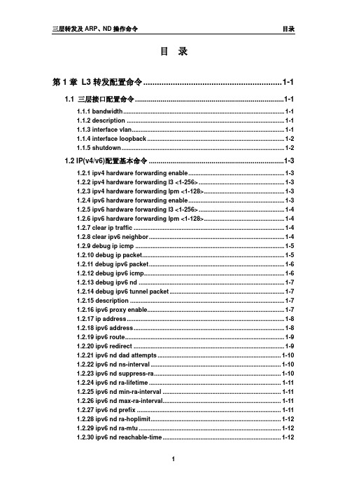
目录第1章L3转发配置命令............................................................. 1-11.1 三层接口配置命令............................................................................ 1-11.1.1 bandwidth.............................................................................................. 1-11.1.2 description ............................................................................................ 1-11.1.3 interface vlan......................................................................................... 1-11.1.4 interface loopback ................................................................................ 1-21.1.5 shutdown............................................................................................... 1-21.2 IP(v4/v6)配置基本命令 ..................................................................... 1-31.2.1 ipv4 hardware forwarding enable........................................................ 1-31.2.2 ipv4 hardware forwarding l3 <1-256>.................................................. 1-31.2.3 ipv4 hardware forwarding lpm <1-128>............................................... 1-31.2.4 ipv6 hardware forwarding enable........................................................ 1-31.2.5 ipv6 hardware forwarding l3 <1-256>.................................................. 1-41.2.6 ipv6 hardware forwarding lpm <1-128>............................................... 1-41.2.7 clear ip traffic ........................................................................................ 1-41.2.8 clear ipv6 neighbor............................................................................... 1-41.2.9 debug ip icmp ....................................................................................... 1-51.2.10 debug ip packet................................................................................... 1-51.2.11 debug ipv6 packet............................................................................... 1-61.2.12 debug ipv6 icmp.................................................................................. 1-61.2.13 debug ipv6 nd ..................................................................................... 1-71.2.14 debug ipv6 tunnel packet................................................................... 1-71.2.15 description .......................................................................................... 1-71.2.16 ipv6 proxy enable................................................................................ 1-71.2.17 ip address............................................................................................ 1-81.2.18 ipv6 address........................................................................................ 1-81.2.19 ipv6 route............................................................................................. 1-91.2.20 ipv6 redirect ........................................................................................ 1-91.2.21 ipv6 nd dad attempts ........................................................................ 1-101.2.22 ipv6 nd ns-interval ............................................................................ 1-101.2.23 ipv6 nd suppress-ra.......................................................................... 1-101.2.24 ipv6 nd ra-lifetime ............................................................................. 1-111.2.25 ipv6 nd min-ra-interval ..................................................................... 1-111.2.26 ipv6 nd max-ra-interval..................................................................... 1-111.2.27 ipv6 nd prefix .................................................................................... 1-111.2.28 ipv6 nd ra-hoplimit............................................................................ 1-121.2.29 ipv6 nd ra-mtu ................................................................................... 1-121.2.30 ipv6 nd reachable-time..................................................................... 1-121.2.31 ipv6 nd retrans-timer ........................................................................ 1-131.2.32 ipv6 nd other-config-flag.................................................................. 1-131.2.33 ipv6 nd managed-config-flag........................................................... 1-131.2.34 ipv6 neighbor .................................................................................... 1-141.2.35 interface tunnel ................................................................................. 1-141.2.36 show ip interface............................................................................... 1-141.2.37 show ip traffic ................................................................................... 1-141.2.38 show ipv6 interface........................................................................... 1-161.2.39 show ipv6 route................................................................................. 1-171.2.40 show ipv6 neighbors ........................................................................ 1-181.2.41 show ipv6 traffic................................................................................ 1-201.2.42 show ipv6 redirect ............................................................................ 1-201.2.43 show ipv6 tunnel............................................................................... 1-211.2.44 tunnel source .................................................................................... 1-211.2.45 tunnel destination............................................................................. 1-211.2.46 tunnel nexthop .................................................................................. 1-211.2.47 tunnel 6to4-relay ............................................................................... 1-211.2.48 tunnel mode ...................................................................................... 1-211.3 IP路由聚合配置命令 ....................................................................... 1-211.3.1 ip fib optimize...................................................................................... 1-211.4 ARP转发配置命令........................................................................... 1-221.4.1 arp ........................................................................................................ 1-221.4.2 clear arp-cache ................................................................................... 1-221.4.3 clear arp traffic.................................................................................... 1-221.4.4 debug arp ............................................................................................ 1-231.4.5 ip proxy-arp......................................................................................... 1-231.4.6 l3 hashselect ....................................................................................... 1-231.4.7 show arp.............................................................................................. 1-241.4.8 show arp traffic ................................................................................... 1-241.5 l3 station movement配置命令....................................................... 1-251.5.1 l3-station-move ................................................................................... 1-25第2章防ARP扫描功能命令....................................................... 2-12.1 anti-arpscan enable........................................................................ 2-12.2 anti-arpscan port-based threshold................................................ 2-12.3 anti-arpscan ip-based threshold ................................................... 2-12.4 anti-arpscan trust ........................................................................... 2-22.5 anti-arpscan trust ip ....................................................................... 2-22.6 anti-arpscan recovery enable ........................................................ 2-22.7 anti-arpscan recovery time ............................................................ 2-32.8 anti-arpscan log enable.................................................................. 2-32.9 anti-arpscan trap enable ................................................................ 2-32.10 show anti-arpscan ........................................................................ 2-42.11 debug anti-arpscan....................................................................... 2-5第3章ARP、ND绑定配置命令.................................................. 3-13.1 ip arp-security updateprotect ........................................................ 3-13.2 ipv6 nd-security updateprotect ..................................................... 3-13.3 ip arp-security learnprotect ........................................................... 3-13.4 ipv6 nd-security learnprotect......................................................... 3-23.5 ip arp-security convert................................................................... 3-23.6 ipv6 nd-security convert ................................................................ 3-23.7 clear ip arp dynamic....................................................................... 3-33.8 clear ipv6 nd dynamic .................................................................... 3-3第4章ARP GUARD配置命令.................................................... 4-14.1 arp-guard ip..................................................................................... 4-1第5章ARP LOCAL PROXY命令.............................................. 5-15.1 ip local proxy-arp............................................................................ 5-1第6章免费ARP发送功能配置命令............................................ 6-16.1 ip gratuitous-arp ............................................................................. 6-16.2 show ip gratuitous-arp................................................................... 6-1第7章KEEPALIVE GATEWAY配置命令................................... 7-17.1 keepalive gateway .......................................................................... 7-17.2 show ip interface ............................................................................ 7-17.3 show keepalive gateway ................................................................ 7-1第1章L3转发配置命令1.1 三层接口配置命令1.1.1bandwidth命令:bandwidth <bandwidth>no bandwidth功能:配置interface vlan 的带宽。
- 1、下载文档前请自行甄别文档内容的完整性,平台不提供额外的编辑、内容补充、找答案等附加服务。
- 2、"仅部分预览"的文档,不可在线预览部分如存在完整性等问题,可反馈申请退款(可完整预览的文档不适用该条件!)。
- 3、如文档侵犯您的权益,请联系客服反馈,我们会尽快为您处理(人工客服工作时间:9:00-18:30)。
Rotary Encoder Interface Spartan-3E Starter KitKen Chapman Xilinx Ltd 20th February 2006With thanks to Peter Alfke (Xilinx Inc.)forRev.2LimitationsLimited Warranty and Disclaimer. These designs are provided to you “as is”. Xilinx and its licensors make and you receive no warranties or conditions, express, implied, statutory or otherwise, and Xilinx specifically disclaims any implied warranties of merchantability, non-infringement, or fitness for a particular purpose. Xilinx does not warrant that the functions contained in these designs will meet your requirements, or that the operation of these designs will be uninterrupted or error free, or that defects in the Designs will be corrected. Furthermore, Xilinx does not warrant or make any representations regarding use or the results of the use of the designs in terms of correctness, accuracy, reliability, or otherwise. Limitation of Liability. In no event will Xilinx or its licensors be liable for any loss of data, lost profits, cost or procurement of substitute goods or services, or for any special, incidental, consequential, or indirect damages arising from the use or operation of the designs or accompanying documentation, however caused and on any theory of liability. This limitation will apply even if Xilinx has been advised of the possibility of such damage. This limitation shall apply not-withstanding the failure of the essential purpose of any limited remedies herein. This design module is not supported by general Xilinx Technical support as an official Xilinx Product. Please refer any issues initially to the provider of the module. Any problems or items felt of value in the continued improvement this reference design would be gratefully received by the author. Ken Chapman Senior Staff Engineer – Spartan Applications Specialist email: chapman@ The author would also be pleased to hear from anyone using PicoBlaze (KCPSM3) or the UART macros with information about your application and how these macros have been useful.Rotary Encoder Interface for Spartan-3E Starter Kit 2Design OverviewThis main purpose of this reference design is to provide an interface to the rotary encoder on the Spartan-3E Starter Kit. However, it is hoped that this document combined with the VHDL code and user constraints file (UCF) may provide useful reference for those less familiar with Spartan-3E devices and looking for advice on how to design using them. Some additional exercises are suggested for self education. The design provided detects left and right rotation of the encoder and uses this to controls which of the 8 simple LEDs is illuminated. The rotary control can also be depressed (with or without simultaneous rotation) and this is used to invert the LEDs. It is only very simple behaviour, but my daughter said it was “cool” and I bet you won’t be able to resist playing with it too!Rotary Encoder8 LEDsTry it now – it only takes 30 seconds! Things to learn from this designInterfacing to a rotary encoder. Constraining pin locations using UCF constraints. Simple VHLD illustrating synchronous design techniques. Using the built in pull-up and pull-down resistors in the input/output blocks. Direct drive of LEDs. Good design practice for higher performance Dedicated flip-flops in the input/output blocks. PERIOD timing constraint. Configuration using iMPACT batch file. As well as the source design files, a compiled configuration bit file is provided which you can immediately download into the Spartan XC3S500E device on your board. It is recommended that you try this to become familiar with what the design does before continuing to read. To make this task really easy the first time, unzip all the files provided into a directory and then double click on ‘install_left_right_leds.bat’. Assuming you have the Xilinx software installed, your board connected with the USB cable and the board powered (don’t forget the switch), then this should open a DOS window and run iMPACT in batch mode to configure the Spartan-3E with the design.Rotary Encoder Interface for Spartan-3E Starter Kit 3Design SizeThis design hardly touches the XCSS500E device actually using just 0.5% of the logic resources in total. Clearly room left for you to add more MAP report Number of occupied Slices: 22 out of 4,656 955 Floorplanner view 1% Total equivalent gate count for design: FPGA Editor view XC3S500ERotary Encoder Interface for Spartan-3E Starter Kit 4Rotary Encoder & SignalsThe Encoder - The basic principle of the rotary encoder is that of a cam connected to a shaft which is used to operate two switches. When in the stationary ‘detent’ position both switches are closed. Then depending on which way the shaft is rotated, one switch will open before other. Likewise, as the rotation continues, one switch will be closed before the other. This diagram only depicts that one sequence of the switches will occur for every 360˚ revolution. The encoder on the board actually repeats the sequence every 18˚ (20 clicks per revolution). The Signals - To provide logic signals that the Spartan-3E device can work with, one side of each switch is connected to ground. So when the switch contacts are closed, the signal to the Spartan-3E is definitely Low or ‘0’. When the switch contacts are opened during rotation, a PULL-UP resistor is required to raise the signal to High or ‘1’. A nice feature of Spartan input/output blocks (IOB) is that they have built in optional PULL-UP and PULL down resistors which save adding external components.Hint – Look at the UCF file to see these resistors being enabled.Turning LEFT VccoTurning RIGHTA=‘0’ VccoGNDB=‘1’These oscilloscope traces were captured on the Starter kit and show the signals being detected by the Spartan-3E. The irregularity of the ‘pulses’ is to be expected given the human input! The red and green brackets indicate the logic levels consistent with the switch positions depicted in the diagram. Note that just looking at the ‘A’ and ‘B’ signals as a snapshot is not enough information to evaluate direction. The sequence of signals has to be evaluated.The encoder on the Starter Kit board has a third simple switch which is closed when you press the shaft towards the base. One side of this switch is connected to 3.3v on the board, so in this case a ‘1’ is generated when pressed and an IOB PULL-DOWN resistor is used to provide a ‘0’ at all other times.Rotary Encoder Interface for Spartan-3E Starter Kit 5In the design provided, you should find that each ‘click’ of the shaft moves the illuminated LED one position only. Note that it is one position every time and not suddenly several positions even if you turn it really slowly or click it one position in an ‘instant’ (try it and see). If this control was for tuning your car radio, you would also expect the same reliable operation to home in on the radio station of your choice. Unfortunately, anything mechanical is prone to bounce and this is very true of switch contacts which are said to ‘chatter’. Although switch manufactures go to considerable lengths to minimise this effect, sometimes we have to design around the issue and that is the case with the rotary encoder interface. This scope trace shows the chatter observed on the ‘A’ switch on one particular occasion. The switch opened and the signal went High for approximately 2.5ms. It then closed for ~1ms, opened for ~1ms, closed again momentarily, before finally settling on truly being open and providing a steady High signal. Even if other cases are not this bad, the interface must deal with them appropriately when they do occur.Contact Bounce2.5ms/div Note – Spartan devices are relatively fast. There are 50,000 clock cycles at 50MHz in the duration of one of these 1ms chatter events.The initial obvious way to determine the direction of rotation is as follows:If ‘A’ goes High whilst ‘B’ is Low then rotation is to the to the Right. If ‘B’ goes High whilst ‘A’ is Low then rotation is to the to the Left.The diagram below indicates how switch chatter could be interpreted as additional rotation ‘clicks’ in either direction even when the intention is only to take one step to the right. Rising edge on ‘A’ with B=‘0’ indicates RIGHT turn Turning RIGHT Switch opening chatter on ‘A’ injects false ‘clicks’ to the right.A BDetent DetentExercise – Implement this ‘obvious’ rotation detector and see how unreliable it is.Switch closing chatter on ‘B’ injects false ‘clicks’ to the left (‘B’ going High whilst ‘A’ is Low).Rotary Encoder Interface for Spartan-3E Starter Kit 6Rotary Contact FilterClearly the objective of the filter is to eliminate the switch chatter completely. This is a achieved by detecting only the first change of the signal and ignoring all subsequent activity on the same signal until the other switch also changes state. Flip-flops provide the ‘memory’ for this function. rotary_q1 Set (‘1’) when A is High and B is High i.e. XNOR Reset (‘0’) when A is Low and B is Low. Remember current state in all other cases.rotary_filter: process(clk) begin if clk'event and clk='1' then rotary_in <= rotary_b_in & rotary_a_in; case rotary_in is when "00" => rotary_q1 <= '0'; rotary_q2 <= rotary_q2; when "01" => rotary_q1 <= rotary_q1; rotary_q2 <= '0'; when "10" => rotary_q1 <= rotary_q1; rotary_q2 <= '1'; when "11" => rotary_q1 <= '1'; rotary_q2 <= rotary_q2; when others => rotary_q1 <= rotary_q1; rotary_q2 <= rotary_q2; end case; end if; end process rotary_filter;rotary_q2 Set (‘1’) when A is Low and B is High i.e. XOR Reset (‘0’) when A is High and B is Low. Remember current state in all other cases. Turning RIGHT(1)A Detent DetentBrotary_q1rotary_q2The bold lines indicate where each signal is being forced and the normal lines indicate where the flip-flop memory is retaining the current state. Although we now have a slightly different signal behaviour, the signals are clean and direction can still be determined.Note that this can all be achieved with a synchronously clocked circuit because the 50MHz clock rate is much faster than any events taking place at the switch. Synchronous design techniques avoid introducing different forms of unreliable behavior as well as leading to maximum efficiency of the Spartan-3E.Rotary Encoder Interface for Spartan-3E Starter Kit 7The following scope traces show the output of the rotary filter compared with the original inputs. It is then possible to determine the direction. Turning RIGHTChatter!Direction and Rotation EventsTurning LEFT Turning LEFT Turning RIGHT This is not a simulation! Hint – Never forget to exploit Spartan programmable logic during test and debugging. It was possible to observe the ‘rotary_q1’ and ‘rotary_q2’ signals on a real oscilloscope by adding temporary connections to pins assigned to the board J4 connector. 0 1 1 0AB rotary_q1 rotary_q2It can be seen that when ‘rotary_q1’ changes from Low to High, the state of ‘rotary_q2’ indicates the direction. We can therefore use ‘rotary_q1’ to determine each event and ‘rotary_q2’ to indicate direction.direction: process(clk) begin if clk'event and clk='1' then delay_rotary_q1 <= rotary_q1; if rotary_q1='1' and delay_rotary_q1='0' then rotary_event <= '1'; rotary_left <= rotary_q2; else rotary_event <= '0'; rotary_left <= rotary_left; end if; end if; end process direction;The Low to High transition of ‘rotary_q1’ is used to form a synchronous pulse and remember the direction of rotation. This maintains synchronous design and is a million times better than using ‘rotary_q1’ as another clock signal.Synchronous pulserotary_q1rotary_eventrotary_q2CErotary_leftExercise – Observe ‘rotary_event’ and ‘rotary_left’ on an oscilloscope.Rotary Encoder Interface for Spartan-3E Starter Kit 8Driving LED’sIn this design the rotary events are used to control a simple 8-bit sift register. Each shift register bit is then optionally inverted (by pushing the rotary press switch) on the way to the output pin which drives the corresponding LED. A 390Ω resistor on the board is used to limit the current to approximately 3.5mA. ‘rotary event’ enables the shift register to operate. Notice how the single clock cycle pulse ensures that the LED pattern only moves by one position. ‘rotarty_left’ is used to determine the direction. 0 0 0 0 0 1 0 0rotary_press_inHint – Signal declarations can be used to define initial values for registers. These are then loaded into the Spartan-3E during configuration. Check that LD4 really is the one to illuminate when you first configure the device.signal led_pattern : std_logic_vector(7 downto 0):= "00010000";GNDExercise 1 – Modify the shift register code such that the illuminated LED stops when it reaches the far left (LD7) or far right (LD0) position.Exercise 2 – The ‘rotary_press’ input is not protected against switch chatter. Design and implement a suitable filter circuit to clean this signal. 1) Implement a test circuit based on a counter to demonstrate that switch chatter is present. 2) Design and implement your anti-chatter circuit. 3) Use your test design to demonstrate that the operation of the switch is now reliable.Rotary Encoder Interface for Spartan-3E Starter Kit 9Although not vital for this very low performance design, the VHDL does includes additional flip-flops which are mapped automatically into the input/output blocks (IOB) of the Spartan-3E device. If you use the FPGA Editor to look inside the IOB blocks, you can see that these flip-flops have been used. IOB for ‘rotary_a’ input. Pad bonds to Pin on package Input buffer Input Flip-flop (IFF) output Flip-flop (OFF) IOB for ‘led(6)’ output. Pad bonds to Pin on package Output bufferIOB Flip-FlopsHow? – All you need to do is include the additional layer of flip-flops connected directly signals defining the pins. The tools will do the rest for you.if clk'event and clk='1' then led <= led_drive; end if;Why bother? Using the IOB flip-flops is good design practice for when designs require higher performance. Using the IOB flip-flops means that the input and output timing is deterministic. In fact, even before you start your design you can know the input and output timing from the Spartan-3E data sheet. Besides, that, why waste them? Setup and hold time at input is fixed All variable paths are now internal and covered by a single (UCF) PERIOD constraint IFF D input Q FD D Q OFF D Q output Clock to output time Is fixed Hint – A period constraint describes the duration (or period) of one clock cycle. In this case the 50MHz clock has a period of 20ns. The tools then attempt to keep all connections between flip-flops short enough to allow the propagation of signals through the interconnect and logic to be less than this value.clk Global clock buffer (DCM can also be very useful )Rotary Encoder Interface for Spartan-3E Starter Kit 10。
