5-487509-7中文资料
UL8750最新英文版
UL 8750Light Emitting Diode (LED) Equipment for Use in Lighting ProductsMA Y 22, 2014 − UL 8750tr1UL Standard for Safety for Light Emitting Diode (LED) Equipment for Use in Lighting Products, UL 8750UL标准安全发光二极管(LED)设备用于照明产品、UL 8750First Edition, Dated November 18, 2009第一个版本,日期为2009年11月18日Summary of Topics 总结的主题This revision to ANSI/UL 8750 includes the following changes in requirements:这个修订ANSI / UL 8750变化包括以下要求:●Clarify requirements for conformal coatings, paragraph 7.7.27.7.2澄清要求保形涂料、段落●Insulation materials in transformers and coils ± Delete paragraph 7.11.2.11 and add Section 7.11.3绝缘材料在变形金刚和线圈±删除段落7.11.2.11 7.11.3并添加部分●Revise Risk of Fire De®nition to include 15 W power limit and revisions to Class 2 and LVLE referencesthroughout the standard修改火的风险包括15 W功率极限和修正二班和LVLE引用标准●Add requirements for supply and load connections添加需求供应和负载连接●Revisions to consolidate electrical spacings in Sections 7.7 and 7.8 and add optional shorting test forclosely-spaced PWB traces修订整合电气间距在章节7.7和7.8和添加可选做空测试间隔太近PWB痕迹●Add requirement for LED array (module) thermal measurement point添加要求LED阵列(模块)热计量点●Add temperature measurement method for polymeric materials when TC is optically radiated添加温度测量方法,当TC光学辐射高分子材料Text that has been changed in any manner or impacted by UL's electronic publishing system is marked with a vertical line in the margin. Changes in requirements are marked with a vertical line in the margin and are followed by an effective date note indicating the date of publication or the date on which the changed requirement becomes effective.文本已经以任何方式改变或影响UL电子出版系统的边缘有一条垂直线。
MAX485中文资料
本文是Maxim 正式英文资料的译文,Maxim 不对翻译中存在的差异或由此产生的错误负责。
请注意译文中可能存在文字组织或翻译错误,如需确认任何词语的准确性,请参考Maxim 提供的英文版资料。
索取免费样品和最新版的数据资料,请访问Maxim 的主页: 。
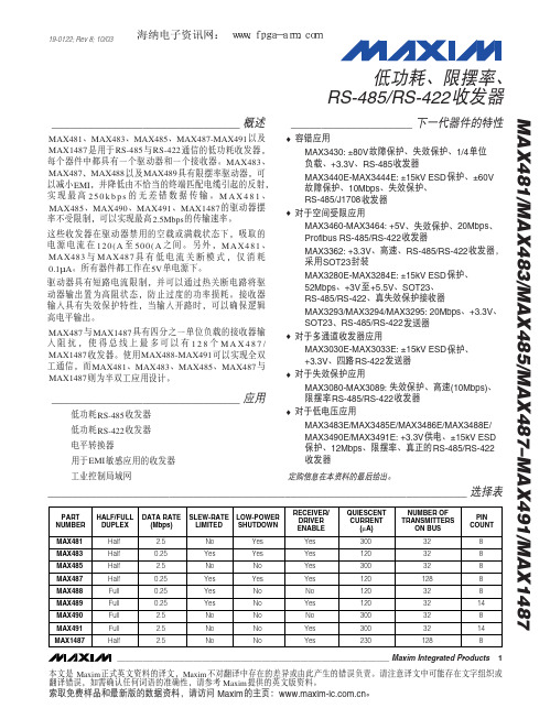
_______________________________概述MAX481、MAX483、MAX485、MAX487-MAX491以及MAX1487是用于RS-485与RS-422通信的低功耗收发器,每个器件中都具有一个驱动器和一个接收器。
MAX483、MAX487、MAX488以及MAX489具有限摆率驱动器,可以减小EMI ,并降低由不恰当的终端匹配电缆引起的反射,实现最高250k b p s 的无差错数据传输。
M A X 481、MAX485、MAX490、MAX491、MAX1487的驱动器摆率不受限制,可以实现最高2.5Mbps 的传输速率。
这些收发器在驱动器禁用的空载或满载状态下,吸取的电源电流在120(A 至500(A 之间。
另外,MAX481、MAX483与MAX487具有低电流关断模式,仅消耗0.1µA 。
所有器件都工作在5V 单电源下。
驱动器具有短路电流限制,并可以通过热关断电路将驱动器输出置为高阻状态,防止过度的功率损耗。
接收器输入具有失效保护特性,当输入开路时,可以确保逻辑高电平输出。
MAX487与MAX1487具有四分之一单位负载的接收器输入阻抗,使得总线上最多可以有128个M A X 487/MAX1487收发器。
使用MAX488-MAX491可以实现全双工通信,而MAX481、MAX483、MAX485、MAX487与MAX1487则为半双工应用设计。
_______________________________应用低功耗RS-485收发器低功耗RS-422收发器电平转换器用于EMI 敏感应用的收发器工业控制局域网____________________下一代器件的特性♦容错应用MAX3430: ±80V 故障保护、失效保护、1/4单位负载、+3.3V 、RS-485收发器MAX3440E-MAX3444E: ±15kV ESD 保护、±60V 故障保护、10Mbps 、失效保护、RS-485/J1708收发器♦对于空间受限应用MAX3460-MAX3464: +5V 、失效保护、20Mbps 、Profibus RS-485/RS-422收发器MAX3362: +3.3V 、高速、RS-485/RS-422收发器,采用SOT23封装MAX3280E-MAX3284E: ±15kV ESD 保护、52Mbps 、+3V 至+5.5V 、SOT23、RS-485/RS-422、真失效保护接收器MAX3293/MAX3294/MAX3295: 20Mbps 、+3.3V 、SOT23、RS-485/RS-422发送器♦对于多通道收发器应用MAX3030E-MAX3033E: ±15kV ESD 保护、+3.3V 、四路RS-422发送器♦对于失效保护应用MAX3080-MAX3089: 失效保护、高速(10Mbps)、限摆率RS-485/RS-422收发器♦对于低电压应用MAX3483E/MAX3485E/MAX3486E/MAX3488E/MAX3490E/MAX3491E: +3.3V 供电、±15kV ESD 保护、12Mbps 、限摆率、真正的RS-485/RS-422收发器MAX481/MAX483/MAX485/MAX487–MAX491/MAX1487低功耗、限摆率、RS-485/RS-422收发器_____________________________________________________________________选择表19-0122; Rev 8; 10/03定购信息在本资料的最后给出。
agilent-5067-5585_chinese.pdf-高灵敏度d1000试剂安全技术说明书
High Sensitivity D1000 Reagents, Part Number 5067-5585*************(24小时)化学品安全技术说明书GHS product identifier 应急咨询电话(带值班时间)::供应商/ 制造商:安捷伦科技贸易(上海)有限公司中国(上海)外高桥自由贸易试验区英伦路412号(邮编:200131)电话号码: 800-820-3278传真号码: 0086 (21) 5048 2818High Sensitivity D1000 Reagents, Part Number 5067-5585化学品的推荐用途和限制用途High Sensitivity D1000 Sample Buffer 5190-6504High Sensitivity D1000 Ladder 5067-5587部件号:部件号(化学品试剂盒):5067-5585安全技术说明书根据 GB/ T 16483-2008 和 GB/ T 17519-2013GHS化学品标识:高灵敏度 D1000 试剂, 部件号 5067-5585推荐用途限制用途High Sensitivity D1000Sample Buffer1 x 300 µl 样品瓶5067-5587High Sensitivity D1000Ladder1 x 20 µl 样品瓶::有关环境保护措施,请参阅第 12 节。
物质或混合物的分类根据 GB13690-2009 和 GB30000-2013紧急情况概述High Sensitivity D1000 Sample Buffer液体。
High Sensitivity D1000 Ladder 液体。
High Sensitivity D1000 Sample Buffer无色。
High Sensitivity D1000 Ladder 无色。
High Sensitivity D1000 Sample Buffer无气味的。
7443552150;中文规格书,Datasheet资料
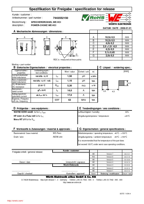
Bezeichnung :description :Marking = part numberEigenschaften / properties Lerrlaufinduktivität/initial inductance Nenn-Induktivität /33%Umgebungstemperatur / temperature:+20°CWE-Perm ME 08-01-01RSt06-01-19ME 05-12-06ME 05-04-16ME 05-03-30ME05-03-16ME 05-01-15NameDatum / dateIt is recommended that the temperature of the part does not exceed 155°C under worst case operating conditions.http://www.we-online.deDatum / date..................................................................................Unterschrift / signatureWürth Elektronik..................................................................................Arbeitstemperatur / operating temperature: -40°C - +155°C Freigabe erteilt / general release:Kunde / customerDraht / wire:Metra HIT 27I für/for R DCE Testbedingungen / test conditions :AIEIW-200Basismaterial / base material:Umgebungstemp. / ambient temperature: -40°C - +105°C F Werkstoffe & Zulassungen / material & approvals :G Eigenschaften / general specifications :Kontrolliert / approvedWürth Elektronik eiSos GmbH & Co. KGD-74638 Waldenburg · Max-Eyth-Strasse 1 - 3 · Germany · Telefon (+49) (0) 7942 - 945 - 0 · Telefax (+49) (0) 7942 - 945 - 400Geprüft / checked .................................................................................................SPEICHERDROSSEL WE-HCI POWER-CHOKE WE-HCIArtikelnummer / part number :7443552150Elektrische Eigenschaften / electrical properties :D Prüfgeräte / test equipment :HP 34401 A & Fluke 54II für/for I DC; Luftfeuchtigkeit / humidity:WAYNE KERR 3260B für/for L 0; I SAT Änderung / modificationVersion 1Version 2Version 3Version 4Version 5Version 6Version 7Bezeichnung :description :H Induktivitätskurve / Inductance curve :ME 08-01-01RSt06-01-19ME 05-12-06ME 05-04-16ME 05-03-30ME05-03-16ME 05-01-15NameDatum / dateD-74638 Waldenburg · Max-Eyth-Strasse 1 - 3 · Germany · Telefon (+49) (0) 7942 - 945 - 0 · Telefax (+49) (0) 7942 - 945 - 400http://www.we-online.deGeprüft / checked Kontrolliert / approvedÄnderung / modificationWürth Elektronik eiSos GmbH & Co. KGVersion 2..............................................................................................................................................Version 1Datum / dateUnterschrift / signature Version 4Würth ElektronikVersion 3Version 6....................................................................................................................................................................Version 5Freigabe erteilt / general release:Kunde / customerVersion 7SPEICHERDROSSEL WE-HCI POWER-CHOKE WE-HCIDATUM / DATE : 2008-01-01Bezeichnung :description :I Temperaturanstieg / Temperature rise curve :ME 08-01-01RSt06-01-19ME 05-12-06ME 05-04-16ME 05-03-30ME05-03-16ME 05-01-15NameDatum / datehttp://www.we-online.deD-74638 Waldenburg · Max-Eyth-Strasse 1 - 3 · Germany · Telefon (+49) (0) 7942 - 945 - 0 · Telefax (+49) (0) 7942 - 945 - 400Würth Elektronik eiSos GmbH & Co. KGWürth ElektronikVersion 3Version 2..........................................................................................................................................Geprüft / checked Kontrolliert / approvedÄnderung / modificationVersion 6...............................................................................................................................................................Datum / dateUnterschrift / signatureVersion 4Version 5Version 1Version 7Freigabe erteilt / general release:Kunde / customerBezeichnung :description :ME 05-12-06ME 05-04-16ME 05-03-30ME05-03-16ME 05-01-15NameDatum / dateD-74638 Waldenburg · Max-Eyth-Strasse 1 - 3 · Germany · Telefon (+49) (0) 7942 - 945 - 0 · Telefax (+49) (0) 7942 - 945 - 400Geprüft / checked Kontrolliert / approvedÄnderung / modificationWürth Elektronik eiSos GmbH & Co. KGVersion 2................................................................................................................................................Version 1Datum / dateUnterschrift / signature Version 4Würth ElektronikVersion 3....................................................................................................................................................................Version 5Freigabe erteilt / general release:Kunde / customerSPEICHERDROSSEL WE-HCI POWER-CHOKE WE-HCIThe Force for tearing off cover tape is 20 to 70 grams in arrow direction150°feeding directionThis electronic component has been designed and developed for usage in general electronic equipment. Before incorporating this component into any equipment where higher safety and reliability is especially required or if there is the possibility of direct damage or injury to human body, for example in the range of aerospace, aviation, nuclear control, submarine, transportation, (automotive control, train control, ship control), transportation signal, disaster prevention, medical, public information network etc, Würth Elektronik eiSos GmbH must be informed before the design-in stage. In addition, sufficient reliability evaluation checks for safety must be performed on every electronic component which is used in electrical circuits that require high safety and reliability functions or performance.分销商库存信息: WURTH-ELECTRONICS 7443552150。
标准化采标产品目录
JIST4102
63
土霉素
土霉素
卫生部药品标准(1989)
英国药典1988
等同国际
64
甲氧氯普胺
甲氧氯普胺
中国药典1990
甲氧氯普胺
日本药典1986
65
200mA、300mA医用诊断X射线机
重大技术装备
200mA医用诊断X射线机
YY0007-90
10~400KV医用X射线设备的辐射防护
IEC407-1973
35
医用棉布
Q/
美国MAI公司实物
36
脱脂纱布
脱脂纱布
Q/
脱脂纱布
英国药典BP88版
国际水平
37
青霉素钠原料药
医药
青霉素钠
中国药典1990年版
青霉素钠
英国药典88年版
先进
38
硫酸链霉素原料药
硫酸链霉素
中国药典1990年版
硫酸链霉素
英国药典88年版
先进
39
ESB高量氨基酸活性饲料酵母
EBS高量氨基酸活性饲料酵母
英国药典93年版
57
单硫酸卡那霉素
中国药典90年版
英国药典ⅩⅪ版
58
盐酸洁霉素
中国药典90年版
英国药典ⅩⅪ版
59
邻苯二甲酸二辛脂(医用)
德BASF公司M5877d-89
60
邻苯二甲酸二辛脂(食用)
德BASF公司M5958d-89
61
邻苯二甲酸二辛脂(普通)
德BASF公司M2189d-89
62
医用缝合线
CNP90
磺胺甲基异同上
USPXX11 BP1993
国际先进水平
ASTM A487-93(98)
Designation:A487/A487M–93(Reapproved1998)An American National Standard Standard Specification forSteel Castings Suitable for Pressure Service1This standard is issued under thefixed designation A487/A487M;the number immediately following the designation indicates the yearof original adoption or,in the case of revision,the year of last revision.A number in parentheses indicates the year of last reapproval.A superscript epsilon(e)indicates an editorial change since the last revision or reapproval.1.Scope1.1This specification2covers low-alloy steels and marten-sitic stainless steels in the normalized and tempered,or quenched and tempered,condition suitable for pressure-containing parts.The weldability of the classes in this speci-fication varies from readily weldable to weldable only with adequate precautions,and the weldability of each class should be considered prior to assembly by fusion welding.1.2Selection will depend on design,mechanical,and ser-vice ers should note that hardenability of some of the grades mentioned may restrict the maximum size at which the required mechanical properties are obtained.1.3The values stated in either inch-pound units or SI units are to be regarded separately as standard.Within the text,the SI units are shown in brackets.The values stated in each system are not exact equivalents;therefore,each system must be used independently of the bining values from the two systems may result in nonconformance with the specifi-cation.Inch-pound units are applicable for material ordered to Specification A487and SI units for material ordered to Specification A487M.2.Referenced Documents2.1ASTM Standards:A370Test Methods and Definitions for Mechanical Testing of Steel Products3A488/A488M Practice for Steel Castings,Welding,Quali-fications of Procedures and Personnel4A703/A703M Specification for Steel Castings,General Requirements,for Pressure-Containing Parts4E165Test Method for Liquid Penetrant Examination5E709Guide for Magnetic Particle Examination52.2American Society of Mechanical Engineers:ASME Boiler and Pressure Vessel Code,Section IX62.3Manufacturers Standardization Society of the Valve and Fittings Industry Standards:7SP-55Quality Standard for Steel Castings-Visual Method3.General Conditions for Delivery3.1Material furnished to this specification shall conform to the requirements of Specification A703/A703M including any supplementary requirements that are indicated in the purchase order.Failure to comply with the general requirements of Specification A703/A703M constitutes nonconformance with this specification.In case of conflict between the requirements of this specification and Specification A703/A703M,this specification shall prevail.4.Ordering Information4.1The inquiry and order should include or indicate the following:4.1.1A description of the casting by pattern number or drawing(dimensional tolerances shall be included on the casting drawing),4.1.2ASTM designation and year of issue,4.1.3Grade and class of steel,4.1.4Options in the specification,and4.1.5The supplementary requirements desired including the standard of acceptance.5.Heat Treatment5.1All castings shall receive a heat treatment indicated in Table1.Preliminary heat treatment prior tofinal heat treatment as well as multiple tempering is permitted.5.2Heat treatment shall be performed after the castings have been allowed to cool below the transformation range.5.3The furnace temperature for heat treating shall be effectively controlled by use of recording-type pyrometers.6.Chemical Composition6.1The steel shall conform to the requirements as to chemical composition prescribed in Table2.Product analysis tolerance shall conform to the product analysis tolerance shown in Specification A703/A703M.Product analysis toler-ances for stainless grades are not presently applicable pending development of these limits.1This specification is under the jurisdiction of ASTM Committee A-1on Steel, Stainless Steel,and Related Alloysand is the direct responsibility of Subcommittee A01.18on Castings.Current edition approved Dec.15,1993.Published April1994.Originally published as A487–st previous edition A487/A487M–91.2For ASME Boiler and Pressure Vessel Code applications see related Specifi-cations SA-487in Section II of that code.3Annual Book of ASTM Standards,V ol01.03.4Annual Book of ASTM Standards,V ol01.02.5Annual Book of ASTM Standards,V ol03.03.6Available from American Society of Mechanical Engineers,345E.47th St., New York,NY10017.7Available from Manufacturer’s Standardization Society of the Valve and Fittings Industry,127Park St.,N.E.Vienna,V A22180.1AMERICAN SOCIETY FOR TESTING AND MATERIALS100Barr Harbor Dr.,West Conshohocken,PA19428 Reprinted from the Annual Book of ASTM Standards.Copyright ASTM7.Tensile Requirements7.1Tensile properties of steel used for the castings shall conform to the requirements prescribed in Table 3.8.Quality8.1The surface of the casting shall be free of adhering sand,scale,cracks,and hot tears as determined by visual examina-tion.Other surface discontinuities shall meet the visual accep-tance standards specified in the order.Visual Method SP-55or other visual standards may be used to define acceptable surface discontinuities and finish.Unacceptable visual surface discon-tinuities shall be removed and their removal verified by visual examination of the resultant cavities.When methods involving high temperatures are used in the removal and repair of discontinuities,the casting shall be preheated to at least the minimum temperature in Table 4.8.2The castings shall not be peened,plugged,or impreg-nated to stop leaks.9.Repair By Welding9.1For castings,other than those intended for use under ASME Boiler and Pressure Vessel Code,repairs shall be made using procedures and welders qualified under Practice A 488/A 488M.9.2On castings intended for use under the ASME Boiler and Pressure Vessel Code,repairs shall be made by procedures and welders qualified under Section IX of that code.9.3After repair welding,all castings shall be postweld heat treated in accordance with Table 4or reheat treated in accordance with Table 1.9.4Weld repairs shall be inspected using the same quality standards as are used to inspect the castings.Re–examination of the weld repair by radiography when Supplementary Re-quirement S 5has been specified will not be necessary when an applicable surface inspection method was used to locate the discontinuity except for the following:TABLE 1Heat Treat RequirementGrade Class Austenitizing Temperature,min,°F [°C]Media A Quenching Cool Below °F [°C]Tempering Temperature,°F [°C]B1A 1600[870]A 450[230]1100[595]1B 1600[870]L 500[260]1100[595]1C 1600[870]A or L500[260]1150[620]2A 1600[870]A 450[230]1100[595]2B 1600[870]L 500[260]1100[595]2C 1600[870]A or L 500[260]1150[620]4A 1600[870]A or L 500[260]1100[595]4B 1600[870]L 500[260]1100[595]4C 1600[870]A or L500[260]1150[620]4D 1600[870]L 500[260]1150[620]4E 1600[870]L 500[260]1100[595]6A 1550[845]A 500[260]1100[595]6B 1550[845]L 500[260]1100[595]7A 1650[900]L 600[315]1100[595]8A 1750[955]A 500[260]1250[675]8B 1750[955]L 500[260]1250[675]8C 1750[955]L 500[260]1250[675]9A 1600[870]A or L 500[260]1100[595]9B 1600[870]L 500[260]1100[595]9C 1600[870]A or L500[260]1150[620]9D 1600[870]L 500[260]1150[620]9E 1600[870]L 500[260]1100[595]10A 1550[845]A 500[260]1100[595]10B 1550[845]L 500[260]1100[595]11A 1650[900]A 600[315]1100[595]11B 1650[900]L 600[315]1100[595]12A 1750[955]A 600[315]1100[595]12B 1750[955]L 400[205]1100[595]13A 1550[845]A 500[260]1100[595]13B 1550[845]L 500[260]1100[595]14A 1550[845]L 500[260]1100[595]16(J31200)A 1600[870]C A 600[315]1100[595]CA15A 1750[955]A or L 400[205]900[480]CA15B 1750[955]A or L 400[205]1100[595]CA15C 1750[955]A or L 400[205]1150[620]DE CA15D 1750[955]A or L 400[205]1150[260]DE CA15M A 1750[955]A or L 400[205]1100[595]CA6NM A 1850[1010]A or L 200[95]1050–1150[565–620]CA6NMB1850[1010]A orL200[95]1225–1275[665–690]E ,F 1050–1150[565–620]GAA 5air,L 5Liquid.BMinimum temperature unless range is specified.CDouble austenitize.DDouble temper with the final temper at alower temperature than the intermediate temper.EAir cool to below 200°F [95°C]after first temper.FIntermediate.GFinal.9.4.1Weld repairs on castings which have leaked on hydro-static test.9.4.2Weld repairs on castings in which the depth of any cavity prepared for repair welding is more than 20%of the wall thickness or 1in.[25mm],whichever is smaller.9.4.3Weld repairs on castings in which any cavity prepared for welding is greater than approximately 10in.2[65cm 2].10.Product Marking10.1Castings shall be marked for material identification with the grade and class symbols (1-A,4-C,CA15-A).11.Keywords11.1steel castings;alloy steel;stainless steel;martensitic stainless steel;pressure containing partsTABLE 2Chemical Requirements (Maximum Percent Unless Range is Given)Grade1.2.4.6.7.8.9.10.11.12.Class Type ABC VanadiumABC Manganese-Molyb-denum ABCDE Nickel-Chromium-MolybdenumAB Manganese Nickel-Chromium-Molybdenum A Nickel-Chromium-Molybdenum-Vanadium A ABC Chromium-Molyb-denum ABCDE Chromium-Molyb-denum AB Nickel-Chromium-Molybde-num AB Nickel-Chromium-Molybdenum AB Nickel-Chromium-MolybdenumCarbon 0.300.300.300.05–0.380.05–0.200.05–0.200.05–0.330.300.05–0.200.05–0.20Manganese 1.00 1.00–1.40 1.00 1.30–1.700.60–1.000.50–0.900.60–1.000.60to 1.000.50–0.800.40–0.70Phosphorus 0.040.040.040.040.040.040.040.040.040.04Sulfur 0.0450.0450.0450.0450.0450.0450.0450.0450.0450.045Silicon 0.800.800.800.800.800.800.800.800.600.60Nickel ......0.40–0.800.40–0.800.70–1.00......1.40–2.000.70–1.100.60–1.00Chromium ......0.40–0.800.40–0.800.40–0.80 2.00–2.750.75–1.100.55–0.900.50–0.800.50–0.90Molybdenum ...0.10–0.300.15–0.300.30–0.400.40–0.600.90–1.100.15–0.300.20–0.400.45–0.650.90–1.20Vanadium 0.04–0.12.........0.03–0.10...............Boron ............0.002–0.006...............Copper............0.15–0.50...............Residual Elements:Copper 0.500.500.500.500.500.500.500.500.500.50Nickel 0.500.50............0.50.........Chromium 0.350.35........................Mo +W 0.25...........................Tungsten ...0.100.100.100.100.100.100.100.100.10Vanadium...0.030.030.03...0.030.030.030.030.03Total content of residual elements1.001.000.600.600.600.601.000.600.500.50Grade13.14.16CA15CA15M CA6NMClass TypeAB Nickel-Molybdenum A Nickel-Molybdenum ALow Carbon Manganese-Nickel (J31200)ABCD Martensitic Chromium AMartensitic ChromiumAB Martensitic Chromium NickelCarbon 0.300.550.12B 0.150.150.06Manganese 0.80–1.100.80–1.10 2.10B 1.00 1.00 1.00Phosphorus 0.040.040.020.0400.0400.04Sulfur 0.0450.0450.020.0400.0400.03Silicon 0.600.600.501.500.65 1.00Nickel 1.40–1.75 1.40–1.75 1.00–1.40 1.001.03.5–4.5Chromium .........11.5–14.011.5–14.011.5–14.0Molybdenum 0.20–0.300.20–0.30...0.500.15–1.00.4–1.0Boron ..................Copper..................Residual Elements Copper 0.500.500.200.500.500.50Nickel ..................Chromium 0.400.400.20.........Molybdenum ......0.10.........Tungsten 0.100.100.100.100.100.10Vanadium0.030.030.020.050.050.05Total content of residual elements0.750.750.500.500.500.50A Proprietary steel composition.BFor each reduction of 0.01%below the specified maximum carbon content,an increase of 0.04%manganese above the specified maximum will be permitted up to a maximum of 2.30%.TABLE3Required Mechanical PropertiesPrevious Designation Grade ClassTensile Strength,Amin,ksi[MPa]Yield Strength,min,ksi[MPa],at0.2%OffsetElongation,2in.[50mm]or4d,min,%Reductionof Area,min%Hardnessmax,HRC[HB]MaxThickness,in.[mm]1N1A85[585]–110[760]55[380]22401Q1B90[620]–115[795]65[450]22451C90[620]65[450]224522[235]2N2A85[585]–110[760]53[365]22352Q2B90[620]–115[795]65[450]22402C90[620]65[450]224022[235]4N4A90[620]–115[795]60[415]18404Q4B105[725]–130[895]85[585]17354C90[620]60[415]183522[235]4D100[690]75[515]173522[235]4QA4E115[795]95[655]15356N6A115[795]80[550]18306Q6B120[825]95[655]12257Q7A115[795]100[690]1530 2.5[63.5]8N8A85[585]–110[760]55[380]20358Q8B105[725]85[585]17308C100[690]75[515]173522[235]9N9A90[620]60[415]18359Q9B105[725]85[585]16359C90[620]60[415]183522[235]9D100[690]75[515]173522[235]9E115[795]95[655]153510N10A100[690]70[485]183510Q10B125[860]100[690]153511N11A70[484]–95[655]40[275]203511Q11B105[725]–130[895]85[585]173512N12A70[485]–95[655]40[275]203512Q12B105[725]–130[895]85[585]173513N13A90[620]–115[795]60[415]183513Q13B105[725]–130[895]85[585]173514Q14A120[825]–145[1000]95[655]143016N16(J31200)A70[485]–95[655]40[275]2235CA15A CA15A140[965]–170[1170]110[760]–130[895]1025CA15CA15B90[620]–115[795]65[450]1830CA15C90[620]60[415]183522[235]CA15D100[690]75[515]173522[235]CA15M CA15M A90[620]–115[795]65[450]1830CA6NM CA6NM A110[760]–135[930]80[550]1535CA6NM CA6NM B100[690]75[515]173523[255]BA Minimum ksi,unless range is given.B Test Methods and Definitions A370,Table3a does not apply to CA6NM.The conversion given is based on CA6NM test coupons.(For example,see ASTM STP756.8)SUPPLEMENTARY REQUIREMENTSThe following supplementary requirements shall not apply unless specified in the purchase order.A list of standardized supplementary requirements for use at the option of the purchaser is included in Specification A703/A703M.Those which are ordinarily considered suitable for use with this specification are given below.Others enumerated in Specification A703/AS1.Unspecified ElementsS4.Magnetic Particle InspectionS5.Radiographic InspectionS8.Charpy Impact TestS8.1In addition to the requirements listed in S8of Speci-fication A703/A703M,the following specific requirements apply to this specification:S8.1.1When S8is specified for Grades1B,2B,4B,6B, 7A,8B,9B,or10B,impact properties shall be determined by performing a Charpy V-notch impact test at−50°F[−46°C] with a specific minimum average value of15ft-lb[20J]and a specified minimum single value of10ft-lb[14J].Other temperatures may be used upon agreement between the manu-facturer and the purchaser,in which case S8.1.3shall apply. Other higher specified minimum average and single values may be used upon agreement between the manufacturer and the purchaser.S8.1.2Impact requirements for grades other than1B,2B, 4B,6B,7A,8B,9B,and10B shall be agreed upon between the manufacturer and the purchaser.S8.1.3When an impact test temperature other than−50°F [−46°C]is used for those grades listed in S8.1.1,the lowest test temperature at which the material meets the impact requirements shall be stamped with low stress stamps imme-diately ahead of the material symbol on the raised pad(for example,2510B for+25°F[−4°C]and02510B for−25°F [−32°C]).S10.Examination of Weld PreparationS10.1The method of performing the magnetic particle or liquid penetrant test shall be in accordance with Practice E709 or Practice E165.TABLE4Minimum Pre-Heat and Post Weld Heat Treat RequirementsGrade ClassMinimum Pre-HeatTemperature,°F[°C]Post Weld Heat Treat,°F[°C]1A,B200[95]1100[595]A minimum1C200[95]1150[620]A minimum2A,B200[95]1100[595]A minimum2C200[95]1150[620]A minimum4A,B,E200[95]1100[595]A minimum4C,D200[95]1150[620]A minimum6A,B300[150]1100[595]A minimum7A300[150]1100[595]A minimum8A,B,C300[150]1250[675]A minimum9A,B,E300[150]1100[595]A minimum9C,D300[150]1150[620]A minimum10A,B300[150]1100[595]A minimum11A,B300[150]1100[595]A minimum12A,B300[150]1100[595]A minimum13A,B400[205]1100[595]A minimum14A400[205]1100[595]A minimum16(J31200)A50[10]1100[595]A minimumCA15A400[205]1750[955]air cool or liquid quench below400°F[205°C]temper at900°F[480°C]minimum CA15B400[205]1100[595]A minimumCA15C,D400[205]1150[620]A minimumCA15M A400[205]1100[595]A minimumCA6NM A50[10]Final temper between1050[565]and1150[620]CA6NM B50[10]Intermediate PWHT between1225[665]and1275[690]Final temper PWHT1050[565]and1150[620]BA Post weld heat treat temperature must be at or below thefinal tempering temperature.B The intermediate andfinal PWHT temperatures shall be the same as the intermediate andfinal tempering temperatures,respectively,as the original heat treatmentof the castings.Cool to below200°F[95°C]between the intermediate andfinal PWHT.The American Society for Testing and Materials takes no position respecting the validity of any patent rights asserted in connection with any item mentioned in this ers of this standard are expressly advised that determination of the validity of any such patent rights,and the risk of infringement of such rights,are entirely their own responsibility.This standard is subject to revision at any time by the responsible technical committee and must be reviewed everyfive years and if not revised,either reapproved or withdrawn.Your comments are invited either for revision of this standard or for additional standards and should be addressed to ASTM Headquarters.Your comments will receive careful consideration at a meeting of the responsible technical committee,which you may attend.If you feel that your comments have not received a fair hearing you should make your views known to the ASTM Committee on Standards,100Barr Harbor Drive,West Conshohocken,PA19428.。
050-607-5517899中文资料
Part Number F50-A28-3002A90 F50-A28-3003A90 F50-A28-3033A90 F50-A28-3035A90 Assembly Instructions F50-A28-3002A90 F50-A28-3003A90 F50-A28-3033A90 F50-A28-3035A90 Cable Numbers 2YCCY 0.4/2.5 2YCY 0.7/4.4 BT2003 BT3002, TZC75024
Part Number F50-A11-3002A90 F50-A11-3003A90 Cable Numbers 2YCCY 0.4/2.5, 2YC(MS)CY 0.4/2.5 ST121 2YCY 0.7/4.4 RG59B/U, ST120, ST214
Assembly Instruction BBAI-1231 (Apply ITT Cannon Sales Dept.) Right Angle Crimp Plug Screw Coupling
max485esa中文资料
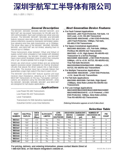
General DescriptionThe MAX481, MAX483, MAX485, MAX487–MAX491, andMAX1487 are low-power transceivers for RS-485 and RS-422 communication. Each part contains one driver and onereceiver. The MAX483, MAX487, MAX488, and MAX489feature reduced slew-rate drivers that minimize E MI andreduce reflections caused by improperly terminated cables,thus allowing error-free data transmission up to 250kbps.The driver slew rates of the MAX481, MAX485, MAX490,MAX491, and MAX1487 are not limited, allowing them totransmit up to 2.5Mbps.These transceivers draw between 120µA and 500µA ofsupply current when unloaded or fully loaded with disableddrivers. Additionally, the MAX481, MAX483, and MAX487have a low-current shutdown mode in which they consumeonly 0.1µA. All parts operate from a single 5V supply.Drivers are short-circuit current limited and are protectedagainst excessive power dissipation by thermal shutdowncircuitry that places the driver outputs into a high-imped-ance state. The receiver input has a fail-safe feature thatguarantees a logic-high output if the input is open circuit.The MAX487 and MAX1487 feature quarter-unit-loadreceiver input impedance, allowing up to 128 MAX487/MAX1487 transceivers on the bus. Full-duplex communi-cations are obtained using the MAX488–MAX491, whilethe MAX481, MAX483, MAX485, MAX487, and MAX1487are designed for half-duplex applications.________________________Applications Low-Power RS-485 Transceivers Low-Power RS-422 Transceivers Level Translators Transceivers for EMI-Sensitive Applications Industrial-Control Local Area Networks__Next Generation Device Features o For Fault-Tolerant Applications MAX3430: ±80V Fault-Protected, Fail-Safe, 1/4Unit Load, +3.3V, RS-485 Transceiver MAX3440E–MAX3444E: ±15kV ESD-Protected,±60V Fault-Protected, 10Mbps, Fail-Safe, RS-485/J1708 Transceivers o For Space-Constrained Applications MAX3460–MAX3464: +5V, Fail-Safe, 20Mbps,Profibus RS-485/RS-422 Transceivers MAX3362: +3.3V, High-Speed, RS-485/RS-422Transceiver in a SOT23 Package MAX3280E–MAX3284E: ±15kV ESD-Protected,52Mbps, +3V to +5.5V, SOT23, RS-485/RS-422,True Fail-Safe Receivers MAX3293/MAX3294/MAX3295: 20Mbps, +3.3V,SOT23, RS-485/RS-422 Transmitters o For Multiple Transceiver Applications MAX3030E–MAX3033E: ±15kV ESD-Protected,+3.3V, Quad RS-422 Transmitters o For Fail-Safe Applications MAX3080–MAX3089: Fail-Safe, High-Speed (10Mbps), Slew-Rate-Limited RS-485/RS-422Transceiverso For Low-Voltage ApplicationsMAX3483E/MAX3485E/MAX3486E/MAX3488E/MAX3490E/MAX3491E: +3.3V Powered, ±15kVESD-Protected, 12Mbps, Slew-Rate-Limited,True RS-485/RS-422 Transceivers For pricing, delivery, and ordering information, please contact Maxim Direct at1-888-629-4642, or visit Maxim Integrated’s website at .______________________________________________________________Selection Table19-0122; Rev 10; 9/14PARTNUMBERHALF/FULL DUPLEX DATA RATE (Mbps) SLEW-RATE LIMITED LOW-POWER SHUTDOWN RECEIVER/DRIVER ENABLE QUIESCENT CURRENT (μA) NUMBER OF RECEIVERS ON BUS PIN COUNT MAX481Half 2.5No Yes Yes 300328MAX483Half 0.25Yes Yes Yes 120328MAX485Half 2.5No No Yes 300328MAX487Half 0.25Yes Yes Yes 1201288MAX488Full 0.25Yes No No 120328MAX489Full 0.25Yes No Yes 1203214MAX490Full 2.5No No No 300328MAX491Full 2.5No No Yes 3003214MAX1487 Half 2.5No No Yes 2301288Ordering Information appears at end of data sheet.找电子元器件上宇航军工MAX481/MAX483/MAX485/MAX487–MAX491/MAX1487Low-Power, Slew-Rate-LimitedRS-485/RS-422 TransceiversPackage Information For the latest package outline information and land patterns, go to . Note that a “+”, “#”, or “-”in the package code indicates RoHS status only. Package drawings may show a different suffix character, but the drawing pertains to the package regardless of RoHS status.16Low-Power, Slew-Rate-Limited RS-485/RS-422 TransceiversMAX481/MAX483/MAX485/MAX487–MAX491/MAX1487Maxim Integrated cannot assume responsibility for use of any circuitry other than circuitry entirely embodied in a Maxim Integrated product. No circuit patent licenses are implied. Maxim Integrated reserves the right to change the circuitry and specifications without notice at any time. The parametric values (min and max limits) shown in the Electrical Characteristics table are guaranteed. Other parametric values quoted in this data sheet are provided for guidance.Maxim Integrated 160 Rio Robles, San Jose, CA 95134 USA 1-408-601-100017©2014 Maxim Integrated Products, Inc.Maxim Integrated and the Maxim Integrated logo are trademarks of Maxim Integrated Products, Inc.。
- 1、下载文档前请自行甄别文档内容的完整性,平台不提供额外的编辑、内容补充、找答案等附加服务。
- 2、"仅部分预览"的文档,不可在线预览部分如存在完整性等问题,可反馈申请退款(可完整预览的文档不适用该条件!)。
- 3、如文档侵犯您的权益,请联系客服反馈,我们会尽快为您处理(人工客服工作时间:9:00-18:30)。
5-487509-7 Product Details
Home | Customer Support | Suppliers | Site Map | Privacy Policy | Browser Support
© 2008 Tyco Electronics Corporation All Rights Reserved Search
Products Documentation Resources My Account Customer Support
Home > Products > By Type > Ribbon, SATA/SAS/Mini-SAS & Flat Flex Wire Connectors > Product Feature Selector > Product Details
5-487509-7
Active Flexible Film Connectors
Always EU RoHS/ELV Compliant (Statement of Compliance)
Product Highlights:
?Connector
? 2.54 mm Centerline
?Connector Type = Trio-Mate
?Number of Positions = 8
?Number of Rows = Single
View all Features | Find Similar
Products
Check Pricing &
Availability
Search for Tooling
Product Feature
Selector
Contact Us About
This Product
Quick Links
Documentation & Additional Information
Product Drawings:
?TRIO MATE VERTICAL CABLE ENTRY FOR 1.57 [.062] THK P...
(PDF, English)
Catalog Pages/Data Sheets:
?None Available
Product Specifications:
?None Available
Application Specifications:
?None Available
Instruction Sheets:
?None Available
CAD Files:
?None Available
List all Documents Additional Information:
?Product Line Information
Additional Product Images: ?PCB Layout
Related Products:
?Tooling
Product Features (Please use the Product Drawing for all design activity)
Product Type Features:
?Product Type = Connector
?Connector Type = Trio-Mate
?Number of Positions = 8
?PCB Thickness (mm [in]) = 1.60 [0.063]
?Mating Connector Lock = Without
?Mating Polarization = Without
?Mounting Ears = Without
?Color = Black
Mechanical Attachment:
?Panel Attachment = Without
Termination Related Features:
?Termination (Solder) Post Length (mm [in]) =
4.06 [0.160]
Body Related Features:
?Centerline (mm [in]) = 2.54 [0.100]
?Number of Rows = Single
?Cable Entry Angle = Vertical Contact Related Features:
?Contact Mating Area Plating = Bright Tin
?Contact Material = Phosphor Bronze
Housing Related Features:
?Housing Material = Thermoplastic Polyester
?Housing Flammability Rating = UL 94V-0
Industry Standards:
?RoHS/ELV Compliance = RoHS compliant, ELV
compliant
?Lead Free Solder Processes = Wave solder
capable to 240°C, Wave solder capable to 260°
C, Wave solder capable to 265°C
?RoHS/ELV Compliance History = Always was
RoHS compliant
Conditions for Usage:
?Terminate To = Printed Circuit Board
Other:
?Brand = AMP
Provide Website Feedback | Contact Customer Support。