基于Comsol的窄带滤波器的设计与仿真
毕业设计(论文)LC带通滤波器的设计与仿真设计
摘要随着电子信息的发展,滤波器作为信号处理的不可缺少的部分,也得到了迅速的发展。
LC滤波器作为滤波器的一个重要组成部分,它的应用相当的广泛。
因此对于它的设计也受到人们的广泛关注。
如何设计利用简单的方法设计出高性能的LC滤波器是人们一直研究的课题。
本文从滤波器的基本概念着手,层层深入的介绍了LC带通滤波器的设计过程,按照滤波器的经典设计方法,运用前人得出的一些数据手册,通过对实例的研究,简单的设计出了LC 带通滤波器。
然后把设计出的电路在Multisim8.3.30软件上进行仿真,最后把得出的结果与通过用matlab 7.1中信号处理工具箱里专用的滤波器设计分析工具fdatool设计出的滤波器进行对比,得出方法的有效性。
关键词:LC带通滤波器设计Multisim8 fdatool 仿真ABSTRACTWith the development of electronic information, signal processing filter as an indispensable part, has been rapid development. LC filter filter as an important part of its application of a broad. Therefore it is designed also to be people's attention. How to design a simple way to design high-performance LC filter people had been studying the subject.From the basic concept of filter start layers of depth on the LC filter with the design process, in accordance with the filter of classical design methods, the use of their predecessors that some data sheet, through the example of the study, the simple Designed to bring the LC filter. And then design a circuit in Multisim8.3.30 software simulation, the results of the final and by using matlab 7.1 signal processing in the toolbox for the filter design analysis tool designed to filter fdatool compared draw The effectiveness of the method.Keywords: LC band-pass filter design Multisim8 fdatool Simulation目录第一章绪论 (1)1.1滤波器简介 (1)1.1.1滤波器的概念 (1)1.1.2滤波器的种类 (2)1.2L C滤波器概述 (4)1.2.1L C滤波器的两种类型 (4)1.3国内外滤波器的发展和研究现状 (5)1.3.1滤波器的发展状况 (5)1.3.2国内外投入滤波器产业概况 (6)1.3.3滤波器的前景 (7)1.3.4几种新型滤波器介绍 (8)1.4研究工作概要和内容安排 (9)1.4.1研究工作概要 (9)1.4.2论文章节安排 (9)第二章滤波器的特性 (11)2.1理想滤波器的特性 (11)2.2实际滤波器的特性 (14)2.2.1巴特沃斯特性 (15)2.2.2切比雪夫特性 (16)2.2.3贝塞尔特性 (16)2.2.4椭圆特性 (17)第三章L C带通滤波器的设计 (19)3.1归一化切比雪夫低通滤波器 (19)3.1.1切比雪夫滤波器 (19)3.1.2阶数的决定 (20)3.1.3归一化切比雪夫低通滤器 (21)3.2由低通到带通的变换 (23)3.2.1理论分析 (24)3.2.2实际应用 (28)3.3实例研究 (30)第四章滤波器的仿真 (35)4.1f d a t o o l工具的介绍和应用 (35)4.2M u l t i s i m8的介绍及应用 (37)4.2.1电路的创建 (38)4.2.2仿真 (39)结束语 (43)致谢 (45)参考文献 (47)第一章绪论当今的社会是一个信息化社会,信号的处理是人们不可避免的问题,因此滤波器作为信号处理的装置得到广泛的应用。
基于局部三维协同仿真技术的X波段窄带腔体滤波器设计

基于局部三维协同仿真技术的X波段窄带腔体滤波器设计
谭士杰
【期刊名称】《磁性材料及器件》
【年(卷),期】2010(041)003
【摘要】从耦合矩阵出发,建立耦合谐振型滤波器电路模型.利用Ansoft的Designer仿真软件对滤波器模型进行分析优化, 得到滤波器级间耦合系数和输入、输出端口耦合系数等滤波器电路设计参数.根据得到的滤波器电路设计参数,应用Ansoft的HFSS软件分别建立滤波器物理级间耦合物理窗以及输入、输出端口等
局部物理模型并对其进行分析优化得到所需物理尺寸参数.利用局部仿真参数建立
整体滤波器仿真物理模型,通过分析优化最终设计出符合指标要求的腔体滤波器.应
用该方法设计并制作了一个中心频率9GHz、带宽30MHz的腔体滤波器, 设计值
与实测指标吻合很好.
【总页数】5页(P67-70,77)
【作者】谭士杰
【作者单位】中国电子科技集团公司,第九研究所,四川绵阳,621000
【正文语种】中文
【中图分类】TN713
【相关文献】
1.基于HFSS的SIR同轴腔体窄带带阻滤波器设计 [J], 杨中婕;陈董
2.基于SIW的X波段窄带滤波器设计 [J], 方健成;汪晓光
3.局部放电窄带干扰抑制的数字滤波器设计 [J], 林宁;郭灿新;黄成军;邹依依;江秀臣
4.基于SIR的X波段小型化带通滤波器设计 [J], 丁文其;郝张成;霍新平;王镇雷
5.基于SSPP与SRR的X波段可重构带阻滤波器设计 [J], 周彤; 杨晓庆
因版权原因,仅展示原文概要,查看原文内容请购买。
comsol单模光纤仿真案例
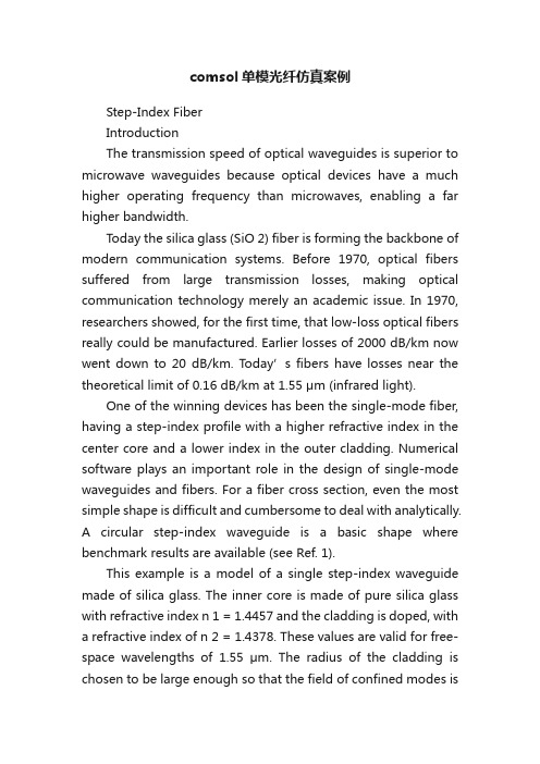
comsol单模光纤仿真案例Step-Index FiberIntroductionThe transmission speed of optical waveguides is superior to microwave waveguides because optical devices have a much higher operating frequency than microwaves, enabling a far higher bandwidth.Today the silica glass (SiO 2) fiber is forming the backbone of modern communication systems. Before 1970, optical fibers suffered from large transmission losses, making optical communication technology merely an academic issue. In 1970, researchers showed, for the first time, that low-loss optical fibers really could be manufactured. Earlier losses of 2000 dB/km now went down to 20 dB/km. Today’s fibers have losses near the theoretical limit of 0.16 dB/km at 1.55 μm (infrared light).One of the winning devices has been the single-mode fiber, having a step-index profile with a higher refractive index in the center core and a lower index in the outer cladding. Numerical software plays an important role in the design of single-mode waveguides and fibers. For a fiber cross section, even the most simple shape is difficult and cumbersome to deal with analytically.A circular step-index waveguide is a basic shape where benchmark results are available (see Ref. 1).This example is a model of a single step-index waveguide made of silica glass. The inner core is made of pure silica glass with refractive index n 1 = 1.4457 and the cladding is doped, with a refractive index of n 2 = 1.4378. These values are valid for free-space wavelengths of 1.55 μm. The radius of the cladding is chosen to be large enough so that the field of confined modes iszero at the exterior boundaries.For a confined mode there is no energy flow in the radial direction, thus the wave must be evanescent in the radial direction in the cladding. This is true only ifOn the other hand, the wave cannot be radially evanescent in the core region. ThusThe waves are more confined when n eff is close to the upper limit in this interval.n eff n 2>n 2n eff n 1<<Model DefinitionThe mode analysis is made on a cross-section in the xy -plane of the fiber. The wave propagates in the z direction and has the formwhere ω is the angular frequency and β the propagation constant. An eigenvalue equation for the electric field E is derived from Helmholtz equationwhich is solved for the eigenvalue λ = ?j β.As boundary condition along the outside of the cladding the electric field is set to zero. Because the amplitude of the field decays rapidly as a function of the radius of the cladding this is a valid boundary condition.Results and DiscussionWhen studying the characteristics of optical waveguides, the effective mode index of a confined mode,as a function of the frequency is an important characteristic.A common notion is the normalized frequency for a fiber. This is defined aswhere a is the radius of the core of the fiber. For this simulation, the effective mode index for the fundamental mode,1.4444 corresponds to a normalized frequency of4.895. The electric and magnetic fields for this mode is shown in Figure 1 below.E x y z t ,,,()E x y ,()e j ωt βz –()=??E ×()×k 02n 2E –0=n eff βk 0-----=V 2πa λ0----------n 12n 22–k 0a n 12n 22–==Figure 1: The surface plot visualizes the z component of the electric field. This plot is for the effective mode index 1.4444.Reference1. A. Yariv, Optical Electronics in Modern Communications, 5th ed., Oxford University Press, 1997.Model Library path:RF_Module/Tutorial_Models/step_index_fiberModeling InstructionsFrom the File menu, choose New.N E W1In the New window, click Model Wizard.M O D E L W I Z A R D1In the Model Wizard window, click 2D.2In the Select physics tree, select Radio Frequency>Electromagnetic Waves, Frequency Domain (emw).3Click Add.4Click Study.5In the Select study tree, select Preset Studies>Mode Analysis.6Click Done.G E O M E T R Y11In the Model Builder window, under Component 1 (comp1) click Geometry 1.2In the Settings window for Geometry, locate the Units section.3From the Length unit list, choose μm.Circle 1 (c1)1On the Geometry toolbar, click Primitives and choose Circle.2In the Settings window for Circle, locate the Size and Shape section.3In the Radius text field, type 40.4Click the Build Selected button.Circle 2 (c2)1On the Geometry toolbar, click Primitives and choose Circle.2In the Settings window for Circle, locate the Size and Shape section.3In the Radius text field, type 8.4Click the Build Selected button.M A T E R I A L SMaterial 1 (mat1)1In the Model Builder window, under Component 1 (comp1) right-click Materials and choose Blank Material.2Right-click Material 1 (mat1) and choose Rename.3In the Rename Material dialog box, type Doped Silica Glass in the New label text field.4Click OK.5Select Domain 2 only.6In the Settings window for Material, click to expand the Material properties section. 7Locate the Material Properties section. In the Material properties tree, select Electromagnetic Models>Refractive Index>Refractive index (n).8Click Add to Material.9Locate the Material Contents section. In the table, enter the following settings:Property Name Value Unit Property groupRefractive index n 1.44571Refractive indexMaterial 2 (mat2)1In the Model Builder window, right-click Materials and choose Blank Material.2Right-click Material 2 (mat2) and choose Rename.3In the Rename Material dialog box, type Silica Glass in the New label text field. 4Click OK.5Select Domain 1 only.6In the Settings window for Material, click to expand the Material properties section. 7Locate the Material Properties section. In the Material properties tree, select ElectromagneticModels>Refractive Index>Refractive index (n).8Click Add to Material.9Locate the Material Contents section. In the table, enter the following settings:Property Name Value Unit Property groupRefractive index n 1.43781Refractive indexE L E C T R O M A G N E T I C W A V E S,F R E Q U E N C Y D O M A I N(E M W)Wave Equation, Electric 11In the Model Builder window, expand the Component 1 (comp1)>Electromagnetic Waves, Frequency Domain (emw) node, then click Wave Equation, Electric 1.2In the Settings window for Wave Equation, Electric, locate the Electric Displacement Field section.3From the Electric displacement field model list, choose Refractive index.M E S H11In the Model Builder window, under Component 1 (comp1) click Mesh 1.2In the Settings window for Mesh, locate the Mesh Settings section.3From the Element size list, choose Finer.4Click the Build All button.S T U D Y1Step 1: Mode Analysis1In the Model Builder window, under Study 1 click Step 1: Mode Analysis.2In the Settings window for Mode Analysis, locate the Study Settings section.3In the Search for modes around text field, type 1.446. Themodes of interest have an effective mode index somewhere between the refractive indices of the two materials. The fundamental mode has the highest index. Therefore, setting the mode index to search around to something just above the core index guarantees that the solver will find the fundamental mode.4In the Mode analysis frequency text field, type c_const/1.55[um]. This frequency corresponds to a free space wavelength of 1.55 μm.5On the Model toolbar, click Compute.R E S U L T SElectric Field (emw)1Click the Zoom Extents button on the Graphics toolbar.2Click the Zoom In button on the Graphics toolbar.3The default plot shows the distribution of the norm of the electric field for the highest of the 6 computed modes (the one with the lowest effective mode index).To study the fundamental mode, choose the highest mode index. Because the magnetic field is exactly 90 degrees out of phase with the electric field you can see both the magnetic and the electric field distributions by plotting the solution at a phase angle of 45 degrees.Data Sets1In the Model Builder window, expand the Results>Data Sets node, then click Study 1/ Solution 1.2In the Settings window for Solution, locate the Solution section.3In the Solution at angle (phase) text field, type 45.Electric Field (emw)1In the Model Builder window, under Results click Electric Field (emw).2In the Settings window for 2D Plot Group, locate the Data section.3From the Effective mode index list, choose 1.4444 (2).4In the Model Builder window, expand the Electric Field (emw) node, then click Surface 1.5In the Settings window for Surface, click Replace Expression in the upper-right corner of the Expression section. From the menu, choose Model>Component1>Electromagnetic Waves, Frequency Domain>Electric>Electric field>emw.Ez - Electricfield, z component.6On the 2D plot group toolbar, click Plot.Add a contour plot of the H-field.7In the Model Builder window, right-click Electric Field (emw) and choose Contour.8In the Settings window for Contour, click Replace Expressionin the upper-right corner of the Expression section. From the menu, choose Model>Component1>Electromagnetic Waves, Frequency Domain>Magnetic>Magnetic field>emw.Hz -Magnetic field, z component.9On the 2D plot group toolbar, click Plot. The distribution of the transversal E and H field components confirms that this is the HE11 mode. Compare the resulting plot with that in Figure 1.。
宽带滤波器的优化设计及其MATLAB仿真

第22卷 第2期计 算 机 仿 真2005年2月 文章编号:1006-9348(2005)02-0110-03宽带滤波器的优化设计及其MAT LAB仿真周英,殷小贡,肖金(武汉大学电气工程学院,湖北武汉430072)摘要:该文介绍了一种宽带滤波器的优化设计方法,即结合采用影像参数法的定K式和m导出式,分别设计相应的低通、高通滤波器,将其级联后得到初步的宽带带通滤波器;然后利用M AT LAB进行仿真调试,对比设计要求和滤波器响应特性,反复调整滤波器LC参数,以获得最好的滤波性能。
这种方法设计的带通滤波器带宽大、噪声低、频率响应特性较理想,并且设计简单、计算容易,也易于实现。
这种设计方法特别适用于本身计算、比较复杂的宽带滤波器的设计。
本文设计的宽带LC滤波器在实际应用中获得了良好的效果。
关键词:滤波器;宽带;影像参数法;仿真中图分类号:TP391.9 文献标识码:AOptimized Design of Broadband Filter and Its MAT LAB SimulationZHOU Y ing,YI N X iao-g ong,XI AO Jin-huang(School of E lectric Engineering,Wuhan University,Wuhan Hubei430072,China)ABSTRACT:The paper presents a kind of optimized design of broadband filter.In this design,we adopt the Image Parame2ters Method,combining the type K with the m educed,which are tw o types of the Method,and design the correspondingLPF and HPF respectively,then unite them in series to obtain a primary broadband BPF.Then we repeat m odifying its LCparameters through M AT LAB simulation,com pared with the design demand and the filter’s responding characteristic to ob2tain the best filtering capability.The filter designed has broad band,low noise,per fect characteristic responding to the fre2quency.I t is sim ple to design,easy to com pute,and easy to realize,too.This method is especially applicable to the designof broadband filter which has its own com plicated com putation and design.The broadband LC filter designed in this paperhas applied in an actual project per fectly.KE YWOR DS:Filter;Broadband;Image parameters method;S imulation1 引言滤波器是通信系统和信号处理中不可缺少的部件。
毕业设计--基于ORCAD的模拟滤波器设计--论文

基于ORCAD的模拟滤波器设计摘要随着现代电子电路技术的发展,模拟滤波器已成为高精度大规模集成电路中的一个基本模块,滤波器参数选择的好坏将在一定程度上影响整个系统的工作稳定性和噪声指标的好坏。
电流模式滤波器的出现于电压模式滤波器之后,它与传统模式的电压模式滤波器相比具有低输入阻抗,高输出阻抗,波动范围大,功耗低,速度快,频带宽,非线性失真小等优点。
因此,本文选择对基于电流控制传送器的模拟滤波器设计。
由于滤波器参数,种类繁多,计算和设计都有一定困难。
近年来随着CAD 和EDA技术的不断发展,为我们分析和设计有源滤波器提供了简单、快捷的方法。
ORCAD正是这样一种电路分析软件。
本文是基于ORCAD的电流模式的模拟滤波器设计。
首先,以二阶带通滤波器的分析优化为例,阐述了用ORCAD对模拟滤波器电路进行分析和优化的过程,给出了具体的分析优化的操作步骤、性能分析曲线、优化结果。
然后,应用电流模式模拟滤波器的设计方法设计出适用于单片集成的滤波器电路,最后,采用ORCAD进行分析、仿真和优化调整。
关键词:滤波器,电流控制传送器, ORCAD 仿真, ORCAD优化The design of Analog Filters Based on ORCADABSTRACTWith the development of modern electronic circuit technology, Analog Filter has become a basic module in high-precision VLSI. The choice of filter parameters will greatly affect the stability and noise indicators quality of the whole system. Current-mode filters turn up after the voltage-mode filters. Current-mode filters,comparing with voltage-mode filters, have following advantages: Low input impedance and high output impedance, big fluctuation range, low power consumption, quick speed, long frequency bandwidth, little non-linear error propagation properties, small non-linear distortion. Therefore, the present paper chooses to design current pattern filter.The calculation and design of filters is every difficult because of numerous parameters and kinds. In recent years, with the CAD and EDA technology developed, the various circuit analysis software functions become more powerful.A simple and quick method was provided for anglicizing and designing APF. ORCAD is such circuit analysis software. This paper is the design of simulation filter based on ORCAD. Firstly, taking the optimization analysis of a second-order band-pass filter for example, the procedure of Optimization by using ORCAD software was demonstrated. Analysis steps of optimize operating, the curve of performance analysis, and optimization results were presented in the paper. Then, filters circuits which are used the single chip integrated were designed by the design methods of current mode filters. Finally, by ORCAD software their performances were analyzed, simulated and optimized.KEY WORDS:Filters ,Current controlled conveyor, Simulation using ORCAD,Optimizing by ORCAD目录前言 (1)第一章滤波器与ORCAD电路优化过程 (3)§1.1滤波器的分类与传输函数 (3)§1.1.1 滤波器的分类 (3)§1.1.2 滤波器的传输函数 (3)§1.2滤波器的主要参数 (5)§1.3ORCAD对滤波器电路的分析与优化 (5)§1.3.1 ORCAD对滤波器电路分析 (6)§1.3.2 ORCAD对电路参数的优化 (8)第二章滤波器的设计方法 (13)§2.1元件替代法设计可调谐电流低通滤波器 (13)§2.2多环反馈电流模式N阶滤波器设计 (16)§2.2.1 系统结构图实现 (16)§2.2.2 N阶低通滤波器的生成 (17)§2.2.3 N阶高通滤波器的生成 (18)§2.3设计实例说明 (20)§2.4电流模式线性组合法 (24)§2.4.1 系统结构框图实现 (25)§2.4.2 滤波器分析 (25)第三章滤波器的仿真与调整 (28)§3.1各种通用滤波器的实现 (28)§3.2各种通用滤波器的仿真 (29)§3.3滤波器的逼近与调整 (29)§3.3.1 滤波器的逼近 (29)§3.3.2 滤波器的调整 (31)结论 (33)参考文献 (34)致谢 (36)附录 (37)前言滤波器是一种能使有用信号顺利通过而同时对无用频率信号进行抑制或衰减的电子装置。
同轴腔体窄带带通滤波器快速设计方法

c i e n t , g r o u p t i me — d e l a y , s i n g l e — c a v i t y r e s o n a t e f r e q u e n c y a n d Q- f a c t o r c a n b e o b t a i n e d f r o m t h e p r o —
方法 通 过 原 型 滤 波 器 查 表 可 以 计 算 滤 波 器 节 数 、 耦合常 数 、 群 时延 、 单腔谐 振频率 、 单腔 Q值等初 始值 ; 通 过 使 用 三 维电磁( E M) 仿 真 软 件 得 到单 腔 调 谐 钉 长 度 和加 载 电 容值 的 对 应 关 系 、 两 个 腔 体 间 耦 合 系 数 及 端 口 抽 头 高 度 等 模 型 S n P参 数 ; 通 过 电路 仿 真 软 件 使 用 集 总 元 件 对 电容 加 载 的 量 值 进 行 优 化 , 极 大 地 提 高 了 仿 真 的速 度 。最 后 使 用 该 协 同仿 真 方 法 设 计 一 同轴 腔 体 滤 波 器 , 并 对仿 真 结 果 进 行 了验 证 。
t o t y p e f i l t e r t a b l e ; t h r o u g h 3 D e l e c t r o ma g n e t i s m ( EM )s i mu l a t i o n s o f t wa r e , t h e c o r r e s p o n d i n g r e l a —
关键 词 : 同轴腔体滤波器 ; 协 同仿真 ; 谐振 ; 三维 电磁 ; 建模
中图分 类号 : T N 7 1 3 . 5
文献标 识 码 : A
文章编 号 : C N 3 2 — 1 4 1 3 ( 2 0 1 3 ) 0 4 — 0 0 9 5 — 0 6
滤波器的仿真设计

• 带内驻波比VSWR: 衡量滤波器通带内信号是否良好匹配传输的一项重要指标。
理想匹配为VSWR=1:1,失配时大于1。对于实际的滤波器
一般要求VSWR小于1.5:1。
• 阻带抑制度Rf: 衡量滤波器选择性能好坏的重要指标,指标越高说明对带外 干扰信号抑制得越好。
滤波器的基本原理
➢ 低通滤波器主要参数指标
➢ 学习目的
学习目的
• 了解滤波器的基本工作原理及指标特性。 • 培养利用ADS软件对集总滤波器和微带滤波器进行设计、
仿真、优化的能力。
学习内容
➢ 滤波器的介绍和基本工作原理 ➢ LC滤波器的仿真设计 ➢ 利用ADS中滤波器设计向导工具进行滤波器设计 ➢ 几种微带结构形式滤波器的仿真设计
滤波器介绍
• AP(dB)=2,表示滤波器的通带传输损耗为2。 • As(dB)=15,表示滤波器截止频率处损耗大于15dB。 • Fp=4GHz,表示滤波器的通带截止频率为4GHz。 • Fs=8GHz,表示滤波器的阻带截止频率为8GHz。 • First Element选择为series,表示第一个元件是串联元件
LC滤波器的仿真设计
➢ 对生成低通滤波电路的仿真设置
起始频率 终止频率 频率步长
仿真参数设置完成,点击【Simulate】按钮,开始仿真!
LC滤波器的仿真设计
➢ 低通滤波器仿真的响应曲线
LC滤波器的仿真设计
➢ 低通滤波器仿真的响应曲线
截止频率4GHz
通带内波动小于2
8GHz处插损大于15dB
达到设计指标!
• 在滤波器选择窗口中选择“Filter Control Window…”,并单击OK 按钮,系统将弹出一个新的滤波器设计向导“Filter DesignGuide” 窗口
窄带带通滤波器设计实例

提 下 , 幅 度 降 低 了整 机 成 本 , 功 解 决 了该 型 接 收 机 中 频 大 成
进 行 了大 量 的详 细研 究 。 随着 技 术 的 发 展 和进 步 , 波 器 技 滤
术 总 是 在 不 断地 进 行 结 构 的变 换 ,改 进 及 设 计 方 法 的更 新 。 毫 不 夸 张 地 说 。 波 器 的 设 计 仍 然 是 当今 无 线 电技 术 的 中心 滤 问 题 之 一 。特 别 是 当 今 的 信 息 时 代 , 息 技 术 产 业 突 飞 猛 进 信 的 今 日 . 磁 波 的各 个 频 段 都 被 各 种 充分 的 理 由拥 挤 不 堪 地 电 占用 掉 . 要 想 获 得 良好 的 抗 干 扰 或 电 子 对 抗 的效 果 , 波 而 滤
5 将 低 通 滤 波 器 变成 带 通 滤 波 器 ) 每 个 电容 并 联 一 个 电感 使 之 谐 振 , 个 电 感 串 联 一 个 电 每
容, 和低损耗 的高 Q磁环绕 制电感 , 即可满足带 通滤波器 的
要 求 。按 照 以上 方 法 及 优 化 后 的 参 数 . 带 通 滤 波 器 进 行 工 对 程 实 现 . 果 与理 论 仿 真 基 本 吻 合 。 结
的 电路 形 式 与 参 数 如 图 1 示 。 所 4用 z5 ) - 0和 如下:
= 0 MH 1 z对 低 通 滤 波 器 去 归 一 化 公 式
.
最 高 可 达 5 B 以上 , 入 损 耗 仅 1d 0d 插 B左 右 。 好 地 解 决 了 较 接 收 机 7 z 频 信 号 的 滤 波 问 题 , 衰 减 有 用 信 号 , 掉 0MH 中 不 省
- 1、下载文档前请自行甄别文档内容的完整性,平台不提供额外的编辑、内容补充、找答案等附加服务。
- 2、"仅部分预览"的文档,不可在线预览部分如存在完整性等问题,可反馈申请退款(可完整预览的文档不适用该条件!)。
- 3、如文档侵犯您的权益,请联系客服反馈,我们会尽快为您处理(人工客服工作时间:9:00-18:30)。
中图分类号:TN713
文献标识码:A
文章编号:2096-4706(2019)15-0036-03
Design and Simulation of Narrowband Filter Based on Comsol
WANG Daoping,WANG Hui (Hefei Normal University,Hefei 230601,China)
损耗等方面较有优势,但仍然不足以满足目前对于高度集成、高速率的信号的处理要求。因此,为了克服以前滤波器的不足之处,
本论文利用 Comsol 软件设计了一款基于光子晶体的窄带带通滤波器。此种窄带滤波器的阻带透射率可低至 0.1 以下,通带的透
射率可高达 0.8,在工程上的应用前景广阔。
关键词:窄带滤波器;阻带透射率;Comsol 软件
Abstract:At present,filters composed of inductors,resistors,and capacitors have been widely used. Compared with earlier filters,they have advantages in frequency selection,stability and loss. However,it is still not enough to meet the current requirements for the processing of highly integrated,high-rate signals. Therefore,in order to overcome the shortcomings of these filters,a narrowband band pass filter based on photonic crystal is designed with Comsol software. This kind of narrowband filter can be as low as 0.1,and the transmission ratio of the passband can be as high as 0.8,and the prospect of engineering application is broad.
滤波器的主要参数(Definitions)有:中心频率(Center Frequency)、 截 止 频 率(CutoffFrequency) 以 及 品 质 因 数(Quality Factor)等。
滤波器的中心频率 f0,一般取 f0=(f1+f2)/2,f1、f2
36 2019.8
ห้องสมุดไป่ตู้ 王道平,等:基于 Comsol 的窄带滤波器的设计与仿真
2 窄带滤波器的结构
在现代微波通信系统中,窄带滤波器有着广泛研究和大 量的应用,尺寸微小、成本较低微带带通滤波器作为选频器 件。常见的几种减小带通滤波器尺寸的方法包括阶梯阻抗谐 振器结构、环型谐振器结构、发夹型谐振器结构、短路支节 结构、缺陷地结构以及交指谐振器结构等几种。
窄带滤波器结构交替使用 λ/2 和 λ/4 谐振器,设计了一 种可以工作在 X 波段的新型的窄带带通滤波器 [2]。
第 15 期
在近代尤其是现代通信领域中,滤波器在各种各样的电 信设备和各种门类的电子信息控制系统之中,均被应用的极 为广泛。它逐渐成为了在所有的电子元器件中使用最多、且
收稿日期:2019-06-17
设计及应用技术十分复杂的一类电子元器件。滤波器性能的 好坏甚至已经逐渐的成为直接决定该电子产品性能优劣的重 要的元器件。因此,对于滤波器相关性能的研究与制造历来 受到各国以及各个品牌公司的青睐与重视。如今,滤波器质 量的好坏已经成为了评价一种电子产品及电子控制系统的其 中一项直接的重要的性能指标。
Keywords:narrowband filter;resistance band transmission;Comsol software
1 研究的背景及意义
在上个世纪 1917 年,美国的科学家与德国两国的科学 家,分别发明出了 LC 滤波器。LC 滤波器的出现,促使美 国出现了首个多路复用系统。自 20 世纪的 50 年代开始,无 源滤波器的技术及应用开始变地日趋成熟。自 60 年代起, 由于计算机科学技术、集成电路工艺和材料工艺的逐渐兴起 及日益成熟的发展,滤波器开始日渐朝着更低的功耗、更 高的精度、更小的体积、更加多的功能、性能更加稳定且 成本愈加低廉的方向发展。在这些方向中,更小的体积、 更多功能以及更好的稳定性逐渐成为了滤波器发展的主要 研究方向。正是因为这些新的研究方向,诞生了各种新型 的滤波器 [1],如 RC 滤波器、数字滤波器、开关电容滤波 器等,这些新型的滤波器开始了快速发展,并且迅速的应 用到了许多广阔的领域。80 年代时,研究的方向主要致力 于各种新型号滤波器的研究,并且认真研究如何提高滤波 器的性能,这使得滤波器的使用范围日渐广泛。从 90 年代 起开始,仍然在不断地对滤波器本身进行研究,同时也在 不断致力于将各种新型滤波器应用于各种产品之上的开发 及研制工作。
2019 年 8 月 10 日 第 3 卷 第 15 期
现代信息科技 Modern Information Technology
Aug.2019 Vol.3 No.15
基于 Comsol 的窄带滤波器的设计与仿真
王道平,王辉
(合肥师范学院,安徽 合肥 230601)
摘 要:目前,由电感、电阻、电容所组成的滤波器已得到广泛应用,与早期的滤波器相比,虽然在频率选择、稳定性及
传统的端藕合型结构和交指型结构的组合,尺寸减小了 近 60%,相比于传统的端藕合滤波器,滤波器结构是完全对 称的 [3]。窄带带通滤波器是按滤波器的幅频特性来定义的, 在数字滤波器需要提取的信号频率处设置一个极点,当 r 的 值越来越接近 1 时,会得到一个较窄的通带和比较陡峭的过 渡带,故称为窄带带通滤波器,简称窄带滤波器 [4]。