皖南电机中英文说明书
AXU系列无污料电机系统说明书

B-46Characteristics B-50Specifications B-48System Configuration B-47Features B-46Brushless DC Motor SystemsAXU SeriesThe AXU Series combines a compact, brushless DC motor with a speed control unit. These systems provide space savings, easy wiring and simple operation.ⅥFeaturesⅷEasy Connection and Simple OperationJust connect the motor connector to the control unit, and the AXU is ready for immediate use. The rate of rotation is easy to adjust using the speed control dial on the front of the speed control unit.ⅷThin and CompactCompared to an AC speed control motor, the use of a brushless DC motor significantly reduces the size of the motor.Motor Length: 1.65 inch (42 mm) for 10 W, 25 W2.24 inch (57 mm) for 40 W, 90 WⅷWide Speed Range and Constant TorqueEven with an available speed range of 100ϳ2000 r/min, the AXUSeries motor maintains a constant torque.ⅷExternal Control PossibleRun/Stop, rotation direction and instantaneous stops can be controlled with external signals.●Superior Speed StabilitySpeed regulation characteristics are Ϫ2% maximum with load, Ϯ1% maximum with voltage and Ϯ1% maximum with temperature.●Acceleration/Deceleration FunctionsAXU Series motors can be set to accelerate and decelerate when the start and stop input is used.●Protective FunctionsThe AXU Series is equipped with protective functions to handle overload, overvoltage, out-of-phase, undervoltage and overspeed. When an abnormality is detected, an alarm is output and the motor comes to a stop.●Motor Construction IP65A grade IP65 indicates protection against jets of water. It is safety if get splashed accidentally. However it is notsuitable for washing the motor nor being operated under the circumstance of being splashed constantly.External Control SignalControl UnitMotorThe gearhead shown in the photograph is sold separately.●When the system is approved under various safety standards, the model names on the motor and control unit nameplates are the approved model names.List of Motor and Control Unit Combinations ➝Page B-57●Details of Safety Standards ➝Page G-2●The EMC value changes according to the wiring and layout. Therefore, the final EMC level must be checked with the motor/control unit incorporated in the equipment.(Sold Separately)B-47Dimensions B-51Connection and Operation B-55Motor and Control Unit Combinations B-57Mounting Brackets Control UnitFlexible Couplings MotorThe system configuration shown is an example. Other configurations are available.ⅥProduct Number CodeⅷMotor and Control UnitⅷGearheadAXU 4 25 A - GNShaft Type GN : Pinion Shaft (for use with GN gearhead)GU : Pinion Shaft (for use with GU gearhead)A : Round ShaftVoltage A : Single-Phase 100-115 VACC : Single-Phase 200-230 VAC S : Three-Phase 200-230 VACOutput Power 10: 10 W (1/75 HP)25: 25 W (1/30 HP)40: 40 W (1/19 HP)90: 90 W (1/8 HP)Motor Frame Size 2: 2.36 in. sq. (60 mm sq.)4: 3.15 in. sq. (80 mm sq.)5: 3.54 in. sq. (90 mm sq.)Series AXU :AXU Series4 GN 50 KAType of Bearings and Shaft SizeKA : Ball bearing type and inch-sized output shaftKHA : Ball bearing type and inch-sized output shaft for higher torqueGear Ratio(Example)50: Gear ratio of 50:110X : Denotes decimal gearhead with 10:1 gear ratioGearhead Type GN : GN type (for use with GN -type pinion shaft motor)GU : GU type (for use with GU -type pinion shaft motor)Gearhead Frame Size 2: 2.36 in. sq. (60 mm sq.)4: 3.15 in. sq. (80 mm sq.)5: 3.54 in. sq. (90 mm sq.)●Gearheads must match the motor installation dimensions and shaft type.ⅥProduct LineⅷAXU Series5GU ⅪKHA (High Power Type)5GU10XK (Decimal Gearhead)[for 5GU ⅪKHA ]●Enter the appropriate gear ratio in the box (Ⅺ) within the gearhead model name.50ϳ180operations, the motor comes to a natural stop if the primary voltage of the driver’s inverter exceeds the permissible value.✽2Motor insulation is recognized as Class A [221°F (105°C)] by UL and CSA standards.B-48Characteristics B-50Specifications B-48Features B-46System Configuration B-47B-49Dimensions B-51Connection and Operation B-55Motor and Control Unit Combinations B-57●AXU210Ⅺ-A : 5:31 in. ϫ5.31 in. (135 mm ϫ135 mm), 0.20 in. (5 mm) thick ●AXU540Ⅺ-A : 7.87 in. ϫ7.87 in. (200 mm ϫ200 mm), 0.20 in. (5 mm) thick ●AXU425Ⅺ-A : 6:50 in. ϫ6.50 in. (165 mm ϫ165 mm), 0.20 in. (5 mm) thick ●AXU590Ⅺ-A :7.87 in. ϫ7.87 in. (200 mm ϫ200 mm), 0.20 in. (5 mm) thick ✽Ambient temperature of the motor is recognized as 32 ˚F ϳ104 ˚F (0 ˚C ϳϩ40 ˚C) by UL and CSA Standards.ⅥGearmotor–Torque TableMaximum T orque When Using a Decimal Gearhead ●2GN ⅪKA with 2GN10XK : 26 lb-in (3 N •m)●5GN ⅪKA with 5GN10XK : 88 lb-in (10 N •m)●4GN ⅪKA ✽with 4GN10XK : 70 lb-in (8 N •m)●5GU ⅪKA with 5GU10XKB : 177 lb-in (20 N •m)✽All gear ratios except 25:1, 30:1, 36:1: 53 lb-in (6 N •m)●5GU ⅪKHA with 5GU10XK : 260 lb-in (30 N •m)ⅥPermissible Overhung Load and Permissible Thrust LoadEnter the gear ratio in the box (Ⅺ) within the model name.●KA type is standard gearhead. KHA type is high-powered gearhead.●A colored background indicates gear shaft rotation in the same direction as the motor shaft; a white background indicates rotation in the opposite direction.●KA type is standard gearhead. KHA type is high-powered gearhead.B-50Characteristics B-50Specifications B-48System Configuration B-47Features B-46ⅥSpeed–Torque Characteristics[N • m ]T o r q u eSpeed [r/min ][0.20.40.1Speed [r/min ]AXU210A-GN /AXU210C-GN /AXU210S-GN AXU210A-A /AXU210C-A /AXU210S-AAXU425A-GN /AXU425C-GN /AXU425S-GN AXU425A-A /AXU425C-A /AXU425S-A[N • m ]T o r q u e[oz-in ]0.050.10[N • m ][oz-in ]0.3Enter the appropriate letter in the box (Ⅺ) within the motor model name. (A : Single-phase 100-115 VAC, C : Single-phase 200-230 VAC, S : Three-phase 200-230 VAC).●Permissible Thrust Load: Avoid thrust loads as much as possible. If a thrust load is unavoidable, keep it to no more than half the motor weight.2Ϫ4 2●Enter the appropriate gear ratio in the box (Ⅺ) within the gearhead model name.Mounting screws are included with gearheads. Dimensions for screws ➝Page B-1334GN25KA~180KA: L = 1.67 (42.5)B-51Connection and Operation B-55Motor and Control Unit Combinations B-57B-52Characteristics B-50Specifications B-48System Configuration B-47Features B-46v Round Shaft TypeAXU425A-A, AXU425C-A, AXU425S-A Round Shaft Type Motor: AXUM425-A Weight: 1.76 lb. (0.8 kg)d A317v Decimal Gearhead(Can be connected to AXU425GN pinion shaft type.)4GN10XKWeight: 0.88 lb. (0.4 kg)d A013v Motor/GearheadAXU540A-GN, AXU540C-GN, AXU540S-GN Pinion Shaft Type Motor Gearhead AXUM540-GN 5GN ⅪKA Weight: 3.1 lb. (1.4 kg)Weight: 3.3 lb. (1.5 kg)d A313AU (5GN3KA ϳ18KA )A313BU (5GN25KA ϳ180KA )v Round Shaft TypeAXU540A-A, AXU540C-A, AXU540S-A Round Shaft Type Motor: AXUM540-A Weight: 3.1 lb. (1.4 kg)v Decimal Gearhead(Can be connected to AXU540GN pinion shaft type.)5GN10XKWeight: 1.32 lb. (0.6 kg)d A0225GN3KA ϳ18KA : L = 1.65 (42)5GN25KA ϳ180KA : L = 2.36 (60)B-53Dimensions B-51Connection and Operation B-55Motor and Control Unit Combinations B-57v Motor/GearheadAXU590A-GU, AXU590C-GU, AXU590S-GU Pinion Shaft Type Motor Gearhead AXUM590-GU 5GU ⅪKA Weight: 3.1 lb. (1.4 kg)Weight: 3.3 lb. (1.5 kg)ⅷKey and Key Slot (Scale 1/2) 2.743 0 v Round Shaft TypeAXU590A-A, AXU590C-A, AXU590S-A Round Shaft Type Motor: AXUM590-A Weight: 3.1 lb. (1.4 kg)v High-Power Type Gearhead5GU ⅪKHA (For AXU590GU type)Weight: 4.2 lb. (1.9 kg)d A038UⅷKey and Key Slot (Scale 1/2)(The key is provided with the gearhead)v Decimal Gearhead5GU10XKB (for 5GU ⅪKA )5GU10XK (for 5GU ⅪKHA )Weight: 1.32 lb. (0.6 kg)d A029v Control UnitAXUD10A, AXUD10C, AXUD10SAXUD25A, AXUD25C, AXUD25SAXUD40A, AXUD40C, AXUD40SAXUD90A, AXUD90C, AXUD90SWeight: 0.88 lb. (0.4 kg)dA293vPanel Cut-Outv Connection Cable (included)B-54Characteristics B-50Specifications B-48Features B-46System Configuration B-47B-55Connection and Operation B-55Motor and Control Unit Combinations B-57ⅥConnection and OperationⅷNames and Functions of Control UnitNotes :●The RUN/STAND-BY switch is not a power ON/OFF switch.●When you want to stop the motor for an extended period, turn off the control unit power.Back of Control Unitsignal terminalsCW inputCOM CCW input SPEED outputALARM outputMotor connectionconnectorPower connection terminals Protective earth terminalFront of Control UnitSpeed potentiometerSpeed setting range is 100ⅷConnection Diagramsv Motor and Control Unit ConnectionMotor ConnectionInsert the motor cable connector into the motor connector (MOTOR) on the control unit. Insert it until a click sound is audible. T o expand the distance between the motor andcontrol unit, use an optional extension cable. The connection can be extended to a maximum of 34.4 feet (10.5 m). Extension cable ➝Page B-57Power ConnectionConnect the included power supply cable to the powersupply terminal of the control unit. When the included power supply cable is not used, use a cable with a diameter equivalent to AWG22 or more. In that case, round crimp terminals with insulation should be used.0mm )Recommended Crimp TerminalsInput terminalsGroundFor the Protective Earth cable, use a cable with a diameter equivalent to AWG18 or more.v OperationThe direction of motor rotation is as viewed from the output shaft end of the motor. "CW" indicates clockwise direction,while "CCW" indicates counterclockwise direction.Operation Using the RUN/STAND-BY SwitchWhen the RUN/ST AND-BY switch is set to the "RUN"position, the motor will run. When it is set to the "ST AND-BY"The direction of rotation depends on how the short circuit bar at the back of control unit is connected. Connect the short circuit bar between the CW and COM or CCW and COM. Do not use the short circuit bar for any other purpose.Operating Using External SignalsSet the RUN/ST ●See "Input Circuit Connection Example" shown on the next page for connection.CW RotationCCW RotationⅷTiming Chartv Operating Using External SignalsRun/direction of Run/instantaneous stop/reversing RUN/STAND-BY SwitchCW inputCCW inputMotor operationSTAND-BYRUNONOFF OFFONCWCCW0.5s ✽When both the CW and CCW inputs are turned on, the motor stops instantaneously.✽Motor does not run for 0.5 s afterinstantaneous stop, if a reversing run signal is input.Note :The CW and CCW input signals must be ON for at least 20 ms.20 ms min.20 ms min.ⅷSignal Input Circuit v Input CircuitvSet the RUN/ST AND-BY switch to the "RUN" position.●Small-capacity switch and relay●Use a small-capacity contact type relay capable of opening and closing 12 VDC, 5 mA.●T ransistor output type controllerRotation Direction of Motor●CW (clockwise) directional operationWhen CW input is turned on, the motor runs in a clockwise direction. When CW input is turned off, the motor stops.●CCW (counterclockwise) directional operationWhen CCW input is turned on, the motor runs in a counterclockwise direction.When CCW input is turned off, the motor stops.When both the CW and CCW inputs are turned on simultaneously, the motor stops instantly. Instantaneous reversing operation is not possible.Notes :●Wait for more than 20 ms when changing input signals of CW and CCW. ●Do not use a solid state relay (SSR) to turn on or off power. The motor and control unit may be damaged if it is used.●When you want to use the controller with a built-in clamp diode, pay attention to the sequence of turning on or off the power.Power ON : Controller ON ➝Control Unit ON Power OFF : Control Unit OFF ➝Controller OFFIf the control unit power is turned on first when connected as shown above, or the controller power is turned off with the control unit power turned on, current will be applied, as indicated by the arrows in the diagram. This may cause the motor to run.When the power is turned on or off simultaneously, the motor may runtemporarily due to differences in power capacity. The controller power must be turned on first, and control unit power must be turned off first.CW COM CCWCW COMCCWCW CCWCOMB-56Characteristics B-50Specifications B-48System Configuration B-47Features B-46ⅷSignal Output Circuit v Output Circuitv Output Circuit Connection ExampleNotes :●The signal output is Open Collector Output.●Use the power supply of 26.4 VDC or less to connect the limit resistance (R) so that output current does not exceed 10 mA.SPEED OutputThe speed output signal is synchronized with the motor speed. The system outputs pulses (with a width ofapproximately 0.5 ms) at a rate of 30 pulses per rotation of the motor output shaft. Y ou can measure the speed output frequency and calculate motor speed.To check the reduced motor speed visually (the speed at the motor output shaft or at the gearhead output shaft), connect a speed indicator SDM496(sold separately). Speed Indicator ➝Page A-214Notes for Connection :●When you want to extend the input/output signal cable, the length must not exceed 6.6ft. (2m). The cable should be as short as possible in order to minimize noise.●Signal wires and motor wires should be kept away from equipment, power cables and other sources of magnetic noise.ⅷSetting the Acceleration/Deceleration TimeThe motor accelerates slowly when it starts up and decelerates slowly when it stops. This acceleration/deceleration time can be set within the range from 0.5 to 10sec (2000 r/min without load). The time can be set using the acceleration/deceleration potentiometer. Remove the front panel of control unit to access the potentiometer.✽The figure shows the control unit with the front panel removed.Motor Speed (r/min) ϭ ϫ 60SPEED Output Frequency [Hz]301TSPEED Output Frequency (Hz) ϭT0.5msB-57Dimensions B-51Connection and Operation B-55Motor and Control Unit Combinations B-57ⅥList of Motor and Control Unit CombinationsⅥAccessories (Sold Separately)ⅷExtension CablesControl Unit Side●Maximum extension length is 34.4 ft. (10.5m).。
小型直流电机安装、运行和维护手册说明书

Installation, Operation and Maintenance ManualSmall DC Motors •56 Frames2Small DC MotorsReceiving and HandlingAcceptance Unpack motor carefully and inspect for possible damage during shipment.Check packing materials and save any instruction tags or wiring diagrams found in the carton. Report any damages or shortages immediately to the local transportation agent.Installation MountingCheck nameplate data on motor before installing to assure the correct rating and that the available power supply agrees with the required motor power supply.Motor should be mounted on a firm foundation.If the foundation is not flat, use shims to prevent misalignment when tightening hold-down bolts. DC motors arc equipped with ball bearings and may be operated in any position.For any position other than base down,new drain holes should be provided so that condensation is allowed to run off. Location should be dry, clean and well ventilated for most satisfactory service. Be sure the possibility of oil seepage into the motor is prevented. Commutator end of the motor should be accessible so that brushes can be conveniently inspected.Mounting Instructions for 56C & 140TC Face Mounted MotorsBefore mounting a “C”face motor to a mating flange,be sure both surfaces and all mounting holes are smooth and free of debris.When mounting into a quill type reducer, make sure the input and output shafts are coated with an anti-seize compound suitable for the application.!ATTENTION:Only qualified electrical personnel familiar with the construction and operation of this equipment and the hazards involved should install,adjust,operate,and/or service this motor.Read and understand this manual in its entirety before proceeding. Failure to observe this precaution could result in personal injury or loss of life.!ATTENTION:High voltage and rotating parts can cause serious or fatal injury. The use of electric machinery, like all other utilization of concentrated power and rotating equipment, can be hazardous. Installation, operation, and maintenance of electric machinery should be performed by qualified personnel.Familiarization with NEMA safety standards, national electrical code and sound local practices is recommended.!ATTENTION:To guard against personal injury or death causedby contact with moving parts, guards (coupling, belt, chain, etc.)must be installed. Machines accessible to the public should be further guarded by screening, guard rails, etc.Small DC Motors 3When mounting through a flexible coupling, verify that there is adequate clearance between the driven equipment shaft, the coupling interface and the motor ck of clearance may result in binding of the shafting and premature bearing failure.Always slide the motor tenon into the mating flange to its full depth before tightening the mounting bolts. Do not allow the motor to hang by the shaft extension while assembling it to the driven equipment (i.e. quill input gear case). This may bend or crease the shaft and damage any seals that are present.Only use the proper mounting bolts. These should be 3/8”-16 threads per inch and sized for length such that engagement into the motor flange does not exceed 9/16”. For example, a gear case with a 3/8” flange thickness requires a bolt that is: 3/8” + 9/16” = 15/16” = Maximum Bolt Length Since 15/16” is not a standard bolt length, a 7/8” bolt or a 1” bolt with a lockwasher can be used.AlignmentShafts should be carefully aligned before tightening any couplings. Inspect couplings and shaft for paint, dirt or burrs. If necessary, remove withsandpaper for proper fit. Pulley or coupling should be carefully fitted. Do not hammer on shaft, pulley or coupling.ApplicationPermanent Magnet “PM”motors are not always designed for across the line starting. This may cause loss of flux resulting in an increase in speed and possibly instability. Wound field motors can be started across the line with full applied voltage. However, for frequent starting or reversing, voltage should be reduced for normal brush and commutator life.Dynamic or regenerative braking methods should not be used unlessprovisions are made to limit the maximum instantaneous current to a value not greater than the maximum allowable peak amperes shown on the nameplate. This also applies to plug reversing the PM motor.ConnectionsAll motors should be installed in accordance with the National Electric Code and local requirements. Fuses, thermal cutouts and other protective devices should be the proper size and rating to safely carry the load and to interrupt the circuit on overloads.!ATTENTION:To guard against motor damage such aspremature failure and/or a loose assembly, use only mountingbolts that are the correct length.A bolt that is too long may cause damage to the motor.4Small DC MotorsConnection diagrams are shown above. Care must be taken to ensure that the dual-voltage shunt field is properly connected.Some DC motors are equipped with a thermostat inside the motor. This thermostat has a normally closed (NC) contact which opens if the motor temperature exceeds design limits due to extended overload operation.Leads from the thermostat are labeled P1& P2and should be connected in series with the drive “STOP” button (refer to the previous figure).!ATTENTION:Ground the machine properly to avoid seriousinjury to personnel. Grounding should be in accordance with theNational Electrical Code and consistent with sound local practices.+A1High Voltage Connection 1, 2Low Voltage Connection 1, 2High VoltageConnection1, 2LowVoltageConnection 1, 2Permanent Magnet Thermostat (if furnished)GroundConnection Connect in Series with Control Stop DeviceEarth Ground Series A2S1+F1F11F2A1+A2S1+F1F11F2+A1A2S1–S2+F1F11F2A1+A2S1+F1F11F2S2F22S2F22F22–S2F22+A1TypeS h u n t S t a b i l i z e d S h u n t a n d C o m p o u n d CCW Rotation Facing Commutator End CW –A2+F1F11–F2+A1A2S1S2A1+A2S1S2F22+A1–A2–A1–A1+A2+F1F11–F2F22+A1A2+F1F11F2F22–A1+A2+F1F11F2F22+A2P1P21Motors with single voltage fields do not have leads F11 & F22. Leads F11 & F22 may be marked F3 & F4, respectively. Connect on low voltage field connection.2Consult motor nameplate to determine value of low and high voltage connection.Small DC Motors5Important:When motors are provided with thermal protection (typicallythermostats), it is important to properly connect and apply thedevices. This will ensure that the motor is properly protectedfrom being operated if thermal limits are reached and/orexceeded.The control system must be configured to reduce themotor load and/or shut down the motor control system to allowthe motor to cool to a level within acceptable operating ranges.If the motor is operated with the thermal protective devicestripped (indicating an over temperature condition), the motorinsulation could be damaged and complete failure of the motorinsulation is possible. In the event of motor failure due to anover temperature condition,Rockwell Automation requires thatmotor thermal protective devices (when supplied) beadequately monitored and incorporated into the motor controlsystem to maintain warranty. Failure on the part of theindividual installing this equipment to take these steps willresult in the factory warranty being voided.OperationThese motors are inherently capable of operating over a wide range ofspeeds and loads. If the motor is not operated on the type of power supplyfor which it was designed, performance will differ from nameplate valuesand applicable standards.The motor should start quickly.If it fails to start,the load may be too great,the applied voltage too low, or the motor improperly connected and/or thecontrol misadjusted (check particularly current (torque) limit adjustment).In any case, immediately disconnect the power and investigate the cause.While operating the motor, observe the performance. Any undue noise,overheating, sparking or erratic performance should be investigated andnecessary corrective action taken to prevent serious damage.Maintenance The fundamental principle of electrical maintenance is keep the apparatusclean and dry.This requires periodic inspection of the motor,the frequencyof inspection depending upon the type of motor and the service.!ATTENTION:Internal parts of this motor may be at line voltage even when motor is not rotating. Disconnect all AC line connections before contacting any internal part.6Small DC MotorsBearingsBall bearings are deep grooved, double shielded with sufficient lubricantpacked into the bearings by the manufacturer for “life lubrication.” Theinitial lubricant is supplemented by a supply packed into larger reservoirs inthe end shield at time of assembly. No grease fittings are provided. Theinitial lubrication is adequate for up to 5 years of operation under normalconditions.Should it become necessary to replace bearings,the bearing bore and cavityshould be thoroughly cleaned and repacked with approximately 1/2teaspoonful of recommended grease.Bearings should be removed with bearing pullers using a center insert in theend of the shaft to protect the shaft center. To reinstall ball bearings, eitherin a press or on the bench, pressure should be applied to the inner race byusing a square faced sleeve or piece of pipe that will fit over the shaft, toavoid damaging the bearing. If a press is not available and a hammer isused,the blows should be transmitted against the sleeve by a block of woodor fiber.BrushesCheck brushes to make certain that they move freely in the holders andmake proper contact with the commutator. Re-place worn brushes. Givecomplete motor identification when ordering parts. New brushes should bepre-radiused to fit the commutator curvature. Blow out the carbon dust.Short brush life and poor commutation may be due to a rough commutator,a shorted armature, or poor undercutting of mica. Dirt and chemicals in theair are common causes of trouble.CommutatorThe commutator should remain a polished surface.Blackening may indicaterough or eccentric commutator. Occasional wiping (power off) with drycanvas or non-linting cloth may suffice. If rough or excessively dirty,smooth with very fine (00) sandpaper lightly with armature rotating. Neveruse emery cloth. Never allow the brushes to wear so short that springtension is lost. The resultant sparking will seriously damage thecommutator.If frequent dressing is required,the cause should be found and corrected.Avery rough commutator should be turned in a lathe, at high speed, with asharp tool.Do not remove more copper than necessary.The mica should beundercut if necessary.An authorized service shop is recommended for this work.Small DC Motors 7General The following should be checked at regular intervals:•Windings should be dry and free of dust, grease, oil, and dirt. Windings may be cleaned by suction cleaners or by wiping. Nozzles on suction type cleaners should be non-metallic.Gummy deposits of dirt and grease may be removed by using a commercially available low volatile solvent.Do not use gasoline or other inflammable solvents.•Terminal connections, assembly screws, bolts and nuts should be tight.They may loosen if motor is not securely bolted and tends to vibrate.•Insulation resistance of motors in service should be checked periodically at approximately the same temperature and humidity conditions to determine possible deterioration of the insulation. When such measurements at regular intervals indicate a wide variation, the cause should be determined. Motor should be reconditioned if the motor has been subjected to excessive moisture, or by rewinding or reinsulating if necessary. Enclosed motors require very little attention. Be sure that external air chamber of fan cooled motors does not become clogged with foreign material which will restrict passage of air.Troubleshooting If trouble develops in operation of motor, verify that:1.The bearings are in normal condition and have been properly lubricated with a high grade,ball bearing lubricant,free of dirt or grit.If dirt enters bearing, flush and relubricate.2.There is no mechanical misadjustment to prevent free rotation of moving parts of motor and drive.3.All bolts and nuts are properly tightened.4.Motor instructions have been carefully carried out.5.The rated voltage is available at the motor terminals.6.The voltage corresponds to the value stamped on the nameplate.7.All connections are properly made in all circuits between motor and control.8.The overload and low voltage devices in control equipment, fuses or other protective devices are in proper working order.9.Brushes are in good condition and are making good con-tact with the commutator.10.The commutator is clean and has smooth polished surface.11.No excessive overload exists on the pare line amperes at full load with nameplate stamping.!ATTENTION:Internal parts of this motor may be at line voltage even when motor is not rotating. Disconnect all AC line connections before contacting any internal part.Online DocumentationThe latest motor information can be obtained from the Allen-BradleyDrives & Motors home page on the World Wide Web at:Publication1325R-UM001B-EN-P Ð A ugust, 2001Supersedes 1325R-UM001A-EN-P dated May, 2001Copyright © 2001 Rockwell Automation. All rights reserved. Printed in USA.。
发电机QF18-22安装使用说明书_中英文

QF系列18~22MW汽轮发电机安装使用维护说明书MANUAL FOR18~22MW TURBO-GENERATOROF QF SERIES0JS・461・402 编制 TRANSLATOR: 刘红蕾 校核 CORRECTOR: 薛守栋 李 霖批准 APPROVER:时间D A T E: 2004.6山东济南发电设备厂SHANDONG JINAN POWER EQUIPMENT FACTORY THE PEOPLE’S REPUBLIC OF CHINA目录Content1.概述第 2 页General2.安装地点及使用条件第2 页Installation site and working conditions3.结构说明第 4 页Structure introduction4.安装说明第 12 页Installation5.使用说明第 18 页Operation6.维护检修说明第 26 页Maintenance7.无刷励磁机使用维护说明 第33 页Brushless Exciter type Operation and Maintenance Instruction 8.保证期第 40 页Guarantee period1. 概述本系列汽轮发电机为QF系列18~22MW空冷三相两极交流同步发电机,额定转速为3000r/min,频率为50Hz。
发电机设计为封闭循环通风系统,径向双流式通风系统。
发电机型号:如QF(NW)-18-2型,QF代表空冷汽轮发电机,18代表容量18兆瓦,2-代表2极,N 代表双支点,W代表无刷励磁方式。
本系列发电机有无刷励磁和静止励磁两种励磁方式供选择。
此系列汽轮发电机的旋转方向,从汽轮机端看为顺时针方向。
GeneralAll this series of Air-Cooled turbo-generators are three-phase, two-pole, synchronous generators whose powers range from 18 MW to 22 MW. Their rated speed and frequency are 3000r/min, 50Hz. The design of generators is closed and circular aeration system and radial double-flow aeration system. Generators model: For example QF(NW)-18-2, QF means Air-Cooled turbo-generators, 18 means Power is 18MW, 2 means 2 poles, N means two supports, W means Brushless Exciter type. This series of generators have two Exciter types, brushless exciter and static exciter. All this series of generators clockwise rotate when looking from driving-end.2. 安装地点及使用条件Installation site and working conditions:2.1 安装地点海拔不超过1000米。
励磁机使用说明0JS.461.381C WBF Exciter operating and maintainning instruction
JPEF
Operating and maintaining Instruction For WBF Brushless AC Exciter
Code Total 10
0JS·461·381C The 3th
(1) Quick response, its response speed is equal to the static excitation system. (2) No slip ring or brush. As a result, there are no carbon powder, noise, difficult maintenance and low durability and so on. (3) No spark caused by slip ring and brush, so the exciter is fit for explosion-proof occasion. (4) Longer shafting compared with that of static excitation. (5) Using nature field suppression, because of the impossibility of setting field discharge switch. (6) Measure the field current indirectly. 2.Operation 2.1 The function of the excitation system is that it can guarantee the stabilization of generator terminal voltage, as well as the forced excitation ability during the network voltage dips when network fault. In order to ensure the safe operation, the greatest generator excitation, during which the current and voltage of the generator has a ten percent surplus, should be taken into account. For forced excitation, the ceiling factor of the rated voltage should be 1.5 at least. If it is in accordance with the design data of steady state and short-circuit, a non-fault operation should be guaranteed. Pleased refer to the electrical data which our factory supply. 2.2 Monitor device 2.2.1 A magnetic relay of the diode is mounted in the exciter field circuit, which can monitor rectifier indirectly. If a diode fault has been tested, a certain method should be made according to 4.2. 2.2.2 A temperature detector with electrical contact, which can help detect the temperature of the exciter and give the signals, is mounted at the air outlet on the side
YP2系列样本 皖南电机
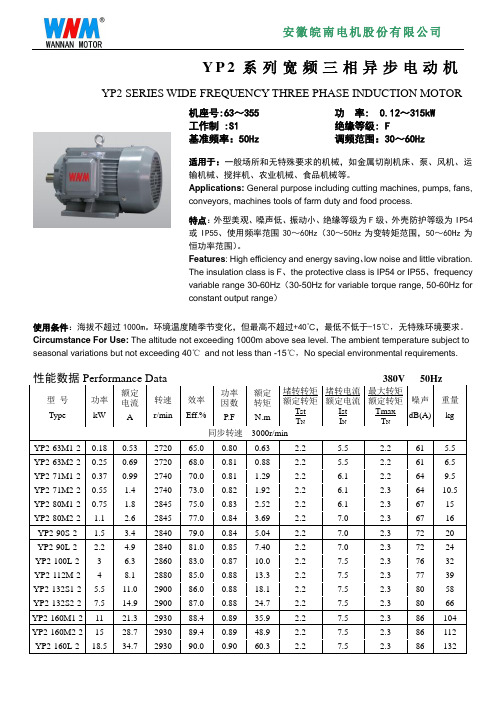
Y P2系列宽频三相异步电动机YP2 SERIES WIDE FREQUENCY THREE PHASE INDUCTION MOTOR机座号:63~355 功率: 0.12~315kW工作制 :S1 绝缘等级: F基准频率:50Hz 调频范围:30~60Hz适用于:一般场所和无特殊要求的机械,如金属切削机床、泵、风机、运输机械、搅拌机、农业机械、食品机械等。
Applications:General purpose including cutting machines, pumps, fans,conveyors, machines tools of farm duty and food process.特点:外型美观、噪声低、振动小、绝缘等级为F级、外壳防护等级为IP54或IP55、使用频率范围30~60Hz(30~50Hz为变转矩范围,50~60Hz为恒功率范围)。
Features: High efficiency and energy saving、low noise and little vibration.The insulation class is F、the protective class is IP54 or IP55、frequencyvariable range 30-60Hz(30-50Hz for variable torque range, 50-60Hz forconstant output range)使用条件:海拔不超过1000m。
环境温度随季节变化,但最高不超过+40℃,最低不低于-15℃,无特殊环境要求。
Circumstance For Use: The altitude not exceeding 1000m above sea level. The ambient temperature subject to seasonal variations but not exceeding 40℃and not less than -15℃,No special environmental requirements.型号Type 功率kW额定电流A转速r/min效率Eff.%功率因数P.F额定转矩N.m堵转转矩额定转矩TstT N堵转电流额定电流IstI N最大转矩额定转矩TmaxT N噪声dB(A)重量kg同步转速3000r/minYP2-63M1-2 0.18 0.53 2720 65.0 0.80 0.63 2.2 5.5 2.2 61 5.5 YP2-63M2-2 0.25 0.69 2720 68.0 0.81 0.88 2.2 5.5 2.2 61 6.5 YP2-71M1-2 0.37 0.99 2740 70.0 0.81 1.29 2.2 6.1 2.2 64 9.5 YP2-71M2-2 0.55 1.4 2740 73.0 0.82 1.92 2.2 6.1 2.3 64 10.5 YP2-80M1-2 0.75 1.8 2845 75.0 0.83 2.52 2.2 6.1 2.3 67 15 YP2-80M2-2 1.1 2.6 2845 77.0 0.84 3.69 2.2 7.0 2.3 67 16 YP2-90S-2 1.5 3.4 2840 79.0 0.84 5.04 2.2 7.0 2.3 72 20 YP2-90L-2 2.2 4.9 2840 81.0 0.85 7.40 2.2 7.0 2.3 72 24 YP2-100L-2 3 6.3 2860 83.0 0.87 10.0 2.2 7.5 2.3 76 32 YP2-112M-2 4 8.1 2880 85.0 0.88 13.3 2.2 7.5 2.3 77 39 YP2-132S1-2 5.5 11.0 2900 86.0 0.88 18.1 2.2 7.5 2.3 80 58 YP2-132S2-2 7.5 14.9 2900 87.0 0.88 24.7 2.2 7.5 2.3 80 66 YP2-160M1-2 11 21.3 2930 88.4 0.89 35.9 2.2 7.5 2.3 86 104 YP2-160M2-2 15 28.7 2930 89.4 0.89 48.9 2.2 7.5 2.3 86 112 YP2-160L-2 18.5 34.7 2930 90.0 0.90 60.3 2.2 7.5 2.3 86 132型号Type 功率kW额定电流A转速r/min效率Eff.%功率因数P.F额定转矩N.m堵转转矩额定转矩TstT N堵转电流额定电流IstI N最大转矩额定转矩TmaxT N噪声dB(A)重量kg同步转速3000r/minYP2-180M-2 22 41.0 2940 90.5 0.90 71.5 2.0 7.5 2.3 89 162 YP2-200L1-2 30 55.4 2950 91.4 0.90 97.0 2.0 7.5 2.3 92 225 YP2-200L2-2 37 67.9 2950 92.0 0.90 120 2.0 7.5 2.3 92 245 YP2-225M-2 45 82.1 2960 92.5 0.90 145 2.0 7.5 2.3 92 294 YP2-250M-2 55 99.8 2965 93.0 0.90 177 2.0 7.5 2.3 93 367 YP2-280S-2 75 135 2970 93.6 0.90 241 2.0 7.5 2.3 94 495 YP2-280M-2 90 160 2970 93.9 0.91 289 2.0 7.5 2.3 94 541 YP2-315S-2 110 195 2975 94.0 0.91 353 1.8 7.1 2.2 96 880 YP2-315M-2 132 233 2975 94.5 0.91 424 1.8 7.1 2.2 96 1000 YP2-315L1-2 160 279 2975 94.6 0.92 514 1.8 7.1 2.2 99 1080 YP2-315L2-2 200 348 2975 94.8 0.92 642 1.8 7.1 2.2 99 1130 YP2-355M-2 250 433 2980 95.3 0.92 801 1.6 7.1 2.2 103 1710 YP2-355L-2 315 544 2980 95.6 0.92 1009 1.6 7.1 2.2 103 1855同步转速1500r/minYP2-63M1-4 0.12 0.44 1310 57.0 0.72 0.87 2.1 4.4 2.2 52 5 YP2-63M2-4 0.18 0.62 1310 60.0 0.73 1.31 2.1 4.4 2.2 52 6.5 YP2-71M1-4 0.25 0.79 1330 65.0 0.74 1.80 2.1 5.2 2.2 55 9 YP2-71M2-4 0.37 1.12 1330 67.0 0.75 2.66 2.1 5.2 2.2 55 9.5 YP2-80M1-4 0.55 1.6 1390 71.0 0.75 3.78 2.4 5.2 2.3 58 15 YP2-80M2-4 0.75 2.0 1390 73.0 0.76 5.15 2.3 6.0 2.3 58 16 YP2-90S-4 1.1 2.9 1390 76.2 0.77 7.56 2.3 6.0 2.3 61 20 YP2-90L-4 1.5 3.7 1390 78.5 0.79 10.3 2.3 6.0 2.3 61 24 YP2-100L1-4 2.2 5.1 1410 81.0 0.81 14.9 2.3 7.0 2.3 64 31 YP2-100L2-4 3 6.7 1410 82.6 0.82 20.3 2.3 7.0 2.3 64 35 YP2-112M-4 4 8.8 1440 84.2 0.82 26.5 2.3 7.0 2.3 65 41 YP2-132S-4 5.5 11.7 1440 85.7 0.83 36.5 2.3 7.0 2.3 71 60 YP2-132M-4 7.5 15.6 1440 87.0 0.84 49.7 2.3 7.0 2.3 71 74 YP2-160M-4 11 22.5 1460 88.4 0.84 72.0 2.2 7.0 2.3 75 108 YP2-160L-4 15 30.0 1460 89.4 0.85 98.1 2.2 7.5 2.3 75 128 YP2-180M-4 18.5 36.1 1470 90.5 0.86 120 2.2 7.5 2.3 76 158 YP2-180L-4 22 42.7 1470 91.0 0.86 143 2.2 7.5 2.3 76 172 YP2-200L-4 30 57.6 1470 92.0 0.86 195 2.2 7.2 2.3 79 241 YP2-225S-4 37 69.9 1475 92.5 0.87 240 2.2 7.2 2.3 81 285 YP2-225M-4 45 84.7 1475 92.8 0.87 291 2.2 7.2 2.3 81 310 YP2-250M-4 55 103 1480 93.0 0.87 355 2.2 7.2 2.3 83 375 YP2-280S-4 75 140 1480 93.8 0.87 484 2.2 7.2 2.3 86 507 YP2-280M-4 90 167 1480 94.2 0.87 581 2.2 7.2 2.3 86 572型号Type 功率kW额定电流A转速r/min效率Eff.%功率因数P.F额定转矩N.m堵转转矩额定转矩TstT N堵转电流额定电流IstI N最大转矩额定转矩TmaxT N噪声dB(A)重量kg同步转速1500r/minYP2-315S-4 110 201 1480 94.5 0.88 710 2.1 6.9 2.2 93 930 YP2-315M-4 132 240 1480 94.8 0.88 852 2.1 6.9 2.2 93 1050 YP2-315L1-4 160 288 1480 94.9 0.89 1032 2.1 6.9 2.2 97 1110 YP2-315L2-4 200 359 1480 95.0 0.89 1291 2.1 6.9 2.2 97 1180 YP2-355M-4 250 443 1490 95.3 0.90 1602 2.1 6.9 2.2 101 1670 YP2-355L-4 315 556 1490 95.6 0.90 2019 2.1 6.9 2.2 101 1830同步转速1000r/minYP2-71M1-6 0.18 0.74 850 56.0 0.66 2.02 1.9 4.0 2.0 52 9 YP2-71M2-6 0.25 0.95 850 59.0 0.68 2.81 1.9 4.0 2.0 52 9.5 YP2-80M1-6 0.37 1.3 885 62.0 0.70 3.99 1.9 4.7 2.0 54 15 YP2-80M2-6 0.55 1.8 885 65.0 0.72 5.94 1.9 4.7 2.1 54 16 YP2-90S-6 0.75 2.3 910 69.0 0.72 7.87 2.0 5.5 2.1 57 20 YP2-90L-6 1.1 3.2 910 72.0 0.73 11.5 2.0 5.5 2.1 57 24 YP2-100L-6 1.5 3.9 920 76.0 0.75 15.6 2.0 5.5 2.1 61 30 YP2-112M-6 2.2 5.6 935 79.0 0.76 22.5 2.0 6.5 2.1 65 39 YP2-132S-6 3 7.4 960 81.0 0.76 29.8 2.1 6.5 2.1 69 55 YP2-132M1-6 4 9.8 960 82.0 0.76 39.8 2.1 6.5 2.1 69 68 YP2-132M2-6 5.5 12.9 965 84.0 0.77 54.4 2.1 6.5 2.1 69 73 YP2-160M-6 7.5 17.2 970 86.0 0.77 73.8 2.0 6.5 2.1 73 104 YP2-160L-6 11 24.5 970 87.5 0.78 108 2.0 6.5 2.1 73 126 YP2-180L-6 15 31.6 970 89.0 0.81 148 2.0 7.0 2.1 73 168 YP2-200L1-6 18.5 38.6 980 90.0 0.81 180 2.1 7.0 2.1 76 215 YP2-200L2-6 22 44.7 980 90.0 0.83 214 2.1 7.0 2.1 76 238 YP2-225M-6 30 59.3 980 91.5 0.84 292 2.0 7.0 2.1 76 288 YP2-250M-6 37 71.1 980 92.0 0.86 361 2.1 7.0 2.1 78 354 YP2-280S-6 45 85.9 980 92.5 0.86 439 2.1 7.0 2.0 80 463 YP2-280M-6 55 105 980 92.8 0.86 536 2.1 7.0 2.0 80 508 YP2-315S-6 75 142 985 93.5 0.86 727 2.0 7.0 2.0 85 860 YP2-315M-6 90 170 985 93.8 0.86 873 2.0 7.0 2.0 85 980 YP2-315L1-6 110 207 985 94.0 0.86 1066 2.0 6.7 2.0 85 1060 YP2-315L2-6 132 245 985 94.2 0.87 1280 2.0 6.7 2.0 85 1135 YP2-355M1-6 160 292 990 94.5 0.88 1543 1.9 6.7 2.0 92 1580 YP2-355M2-6 200 365 990 94.7 0.88 1929 1.9 6.7 2.0 92 1710 YP2-355L-6 250 455 990 94.9 0.88 2412 1.9 6.7 2.0 92 1890型号Type 功率kW额定电流A转速r/min效率Eff.%功率因数P.F额定转矩N.m堵转转矩额定转矩TstT N堵转电流额定电流IstI N最大转矩额定转矩TmaxT N噪声dB(A)重量kg同步转速750r/minYP2-80M1-8 0.18 0.88 645 51.0 0.61 2.67 1.8 3.3 1.9 52 15 YP2-80M2-8 0.25 1.15 645 54.0 0.61 3.70 1.8 3.3 1.9 52 16 YP2-90S-8 0.37 1.49 670 62.0 0.61 5.27 1.8 4.0 1.9 56 20 YP2-90L-8 0.55 2.17 670 63.0 0.61 7.84 1.8 4.0 2.0 56 24 YP2-100L1-8 0.75 2.4 680 71.0 0.67 10.5 1.8 4.0 2.0 59 28 YP2-100L2-8 1.1 3.4 680 73.0 0.69 15.4 1.8 5.0 2.0 59 30 YP2-112M-8 1.5 4.4 690 75.0 0.69 20.8 1.8 5.0 2.0 61 38 YP2-132S-8 2.2 6 705 78.0 0.71 29.8 1.8 6.0 2.0 64 54 YP2-132M-8 3 7.9 705 79.0 0.73 40.6 1.8 6.0 2.0 64 63 YP2-160M1-8 4 10.3 720 81.0 0.73 53.1 1.9 6.0 2.0 68 91 YP2-160M2-8 5.5 13.6 720 83.0 0.74 73.0 2.0 6.0 2.0 68 103 YP2-160L-8 7.5 17.8 720 85.5 0.75 99.5 2.0 6.0 2.0 68 128 YP2-180L-8 11 25.1 730 87.5 0.76 144 2.0 6.6 2.0 70 165 YP2-200L-8 15 34.1 730 88.0 0.76 196 2.0 6.6 2.0 73 224 YP2-225S-8 18.5 41.1 730 90.0 0.76 242 1.9 6.6 2.0 73 255 YP2-225M-8 22 47.4 730 90.5 0.78 288 1.9 6.6 2.0 73 292 YP2-250M-8 30 63.4 735 91.0 0.79 390 1.9 6.6 2.0 75 368 YP2-280S-8 37 77.8 735 91.5 0.79 481 1.9 6.6 2.0 76 475 YP2-280M-8 45 94.1 735 92.0 0.79 585 1.9 6.6 2.0 76 527 YP2-315S-8 55 111 735 92.8 0.81 715 1.8 6.6 2.0 82 840 YP2-315M-8 75 151 735 93.0 0.81 974 1.8 6.6 2.0 82 1020 YP2-315L1-8 90 178 735 93.8 0.82 1169 1.8 6.6 2.0 82 1100 YP2-315L2-8 110 217 735 94.0 0.82 1429 1.8 6.4 2.0 82 1180 YP2-355M1-8 132 261 740 93.7 0.82 1704 1.8 6.4 2.0 90 1610 YP2-355M2-8 160 315 740 94.2 0.82 2065 1.8 6.4 2.0 90 1700 YP2-355L-8 200 387 740 94.5 0.83 2581 1.8 6.4 2.0 90 1850同步转速600r/minYP2-315S-10 45 99.6 590 91.5 0.75 728 1.5 6.2 2.0 82 830 YP2-315M-10 55 121 590 92.0 0.75 890 1.5 6.2 2.0 82 960 YP2-315L1-10 75 162 590 92.5 0.76 1214 1.5 6.2 2.0 82 1080 YP2-315L2-10 90 191 590 93.0 0.77 1457 1.5 6.2 2.0 82 1115 YP2-355M1-10 110 230 590 93.2 0.78 1781 1.3 6.0 2.0 90 1565 YP2-355M2-10 132 275 590 93.5 0.78 2137 1.3 6.0 2.0 90 1685 YP2-355L-10 160 333 590 93.5 0.78 2590 1.3 6.0 2.0 90 1830B14 (机座无底脚、端盖上有小凸缘)机座号 Frame 极数 poles安装尺寸 Mounting Dimension外形尺寸 Overall DimensionDEFGMNPRST凸缘孔数ACADHFL63M 2.4 11 23 4 8.5 75 60 90 0 M5 2.5 4 130 70 130 230 71M 2.4.6 14 30 5 11 85 70 105 0 M6 2.5 4 145 80 145 255 80M 2.4.6.8 19 40 6 15.5 100 80 120 0 M6 3 4 175 145 185 295 90S 2.4.6.8 24 50 8 20 115 95 140 0 M8 3 4 195 155 195 320 90L 2.4.6.8 24 50 8 20 115951400 M8 3 4 195 155 195 345 100L 2.4.6.8 28 60 8 24 130 110 160 0 M8 3.5 4 215 180 245 385 112M2.4.6.82860824130 110 160M83.54240190265400B34 (机座带底脚、端盖上有小凸缘)机座号 Fram e 极数poles 安装尺寸 Mounting Dimension 外形尺寸 Overall DimensionA B C D E F G H K M N P R S T 凸缘孔数AA AB AC AD BB HA HD L63M 2.4110 80 40 11 23 4 8.5 63 7 75 60 90 0 M5 2.54 30 135 130 70 110 8 180 230 71M2.4.6 112 90 45 14 30 5 11 71 7 85 70 105 0 M6 2.54 32 150 145 80 120 8 195 255 80M 2.4.6.8 125 100 50 19 406 15.580 10 100 80 120 0 M6 3 4 32 165 175 145 130 10 214 295 90S2.4.6.8 140 100 56 24 50 8 20 90 10 115 95 140 0 M8 34 34 180 195 155 140 12 250 320 90L 2.4.6.8 140 125 56 24 50 8 20 90 10 115 95 140 0 M8 3 4 34 180 195 155 165 12 250 345 100L 2.4.6.8 160 140 63 28 60 8 24 100 12 130 110 160 0 M8 3.5 4 39 205 215 180 186 14 270 385 112M 2.4.6.8 190 140 70 28 60 8 24 112 12 130 110 160 0 M8 3.5445 230 240 190 180 13 300 400B3(机座带底脚、端盖无凸缘)安装尺寸 Mounting Dimension 外形尺寸 Overall Dimension机座号 Frame 极数 poles ABCDEFGHKAA AB AC AD BB HA HDL63M 2.4 100 80 40 11 23 4 8.5 63 7 30 135 130 70 110 8 180 230 71M2.4.6 112 90 45 14 30 5 11 71 7 32 150 145 801208 195 255 80M 2.4.6.8 125 100 50 19 40 6 15.5 80 10 32 165 175 145 130 10 220 295 90S 2.4.6.8 140 100 56 24 50 8 20 90 10 34 180 195 155 140 12 250 320 90L 2.4.6.8 140 125 56 24 50 8 20 90 10 34 180 195 155 165 12 250 345 100L2.4.6.8 160 140 63 28 60 8 24 100 12 39 205 215 180 186 14 270 385 112M 2.4.6.8 190 140 70 28 60 8 24 112 12 45 230 240 190 180 13 300 400 132S 2.4.6.8 216 140 89 38 80 10 33 132 12 55 270 275 210 186 20 345 470 132M 2.4.6.8 216 1788938801033 1321255 270 275 210 224 20 345 510 160M 2.4.6.8 254 210 108 42 110 12 37 160 14.5 65 320 330 255 260 20 420 615 160L 2.4.6.8 254 254 108 42 110 1237160 14.565 320 330 255 304 20 420 670 180M 2.4.6.8 279 241 121 48 110 14 42.5 180 14.5 70 355 380 280 311 22 455 700 180L 2.4.6.8 279 279 121 48 110 14 42.5 180 14.5 70 355 380 280 349 22 455 740 200L2.4.6.8 318 305 133 55 110 16 49 200 18.5 74 395 420 305 379 26 505 770 225S 4.8 356 286 149 60 140 18 53 225 18.5 78 435 470 335 368 28 560 815 225M 2 356 311 149 55 110 16 49 225 18.5 78 435 470 335 393 28 560 820 225M 4.6.8 356 311 149 60 140 18 53 225 18.5 78 435 470 335 393 28 560 845 250M 2 406 349 168 60 140 18 53 250 24 80 490 510 370 445 30 615 910 250M 4.6.8 406 349 168 65 140 18 58 250 24 80 490 510 370 445 30 615 910 280S 2 457 368 190 65 140 18 58 280 24 90 550 580 410 485 35 680 985 280S4.6.8 457 368 190 75 140 20 67.5 280 24 90 550 580 410 485 35 680 985 280M 2 457 419 190 65 140 18 58 280 24 90 550 580 410 536 35 680 1035 280M 4.6.8 457 419 190 75 140 20 67.5 28024 90550580 410 536 35 680 1035 315S 2 508 406 216 65 140 18 58 315 28 120 635 645 530 570 45 845 1240 315S 4.6.8.10508 406 216 80 170 22 71 315 28 120 635 645 530 570 45 845 1270 315M2508457 216 65 140 1858 315 28 120 635 645 530 610 45 845 1350 315M 4.6.8.10 508 457 216 80 170 2271 315 28 120 635 645 530 610 45 845 1380 315L 2 508 508 216 65 140 18 58 315 28 120 635 645 530 680 45 845 1350 315L 4.6.8.10508 508 216 80 170 227131528 120 635 645 530 680 45 8451380355M2610560 254 75 140 20 67.5 355 28 130 730 710 655 690 52 1010 1500 355M 4.6.8.10 610 560 254 95 170 25 86 355 28 130 730 710 655 690 52 1010 1530 355L 2 610 630 254 75 140 20 67.5 355 28 130 730 710 655 750 52 1010 1500 355L4.6.8.10610630 254 95 170 258635528130 730710655 750521010 1530B5(机座不带底脚、端盖有凸缘)机座号Frame 极数poles安装尺寸Mounting Dimension外形尺寸Overall DimensionD E F G M N P R S T凸缘孔数AC AD HF L63M 2.4 11 23 4 8.5 115 95 140 0 10 3 4 130 70 130 230 71M 2.4.6 14 30 5 11 130 110 160 0 10 3.5 4 145 80 145 255 80M 2.4.6.8 19 40 6 15.5 165 130 200 0 12 3.5 4 175 145 185 295 90S 2.4.6.8 24 50 8 20 165 130 200 0 12 3.5 4 195 155 195 320 90L 2.4.6.8 24 50 8 20 165 130 200 0 12 3.5 4 195 155 195 345 100L 2.4.6.8 28 60 8 24 215 180 250 0 14.5 4 4 215 180 245 385 112M 2.4.6.8 28 60 8 24 215 180 250 0 14.5 4 4 240 190 265 400 132S 2.4.6.8 38 80 10 33 265 230 300 0 14.5 4 4 275 210 315 470 132M 2.4.6.8 38 80 10 33 265 230 300 0 14.5 4 4 275 210 315 510 160M 2.4.6.8 42 110 12 37 300 250 350 0 18.5 5 4 330 255 385 615 160L 2.4.6.8 42 110 12 37 300 250 350 0 18.5 5 4 330 255 385 670 180M 2.4.6.8 48 110 14 42.5 300 250 350 0 18.5 5 4 380 280 430 700 180L 2.4.6.8 48 110 14 42.5 300 250 350 0 18.5 5 4 380 280 430 740 200L 2.4.6.8 55 110 16 49 350 300 400 0 18.5 5 4 420 305 480 770 225S 4.8 60 140 18 53 400 350 450 0 18.5 5 8 470 335 535 815 225M 2 55 110 16 49 400 350 450 0 18.5 5 8 470 335 535 820 225M 4.6.8 60 140 18 53 400 350 450 0 18.5 5 8 470 335 535 845 250M 2 60 140 18 53 500 450 550 0 18.5 5 8 510 370 595 910 250M 4.6.8 65 140 18 58 500 450 550 0 18.5 5 8 510 370 595 910 280S 2 65 140 18 58 500 450 550 0 18.5 5 8 580 410 650 985 280S 4.6.8 75 140 20 67.5 500 450 550 0 18.5 5 8 580 410 650 985 280M 2 65 140 18 58 500 450 550 0 18.5 5 8 580 410 650 1035 280M 4.6.8 75 140 20 67.5 500 450 550 0 18.5 5 8 580 410 650 1035机座号Frame 极数poles安装尺寸Mounting Dimension外形尺寸Overall DimensionA B C D E F G H K M N P R S T AA AB AC AD BB HA HD L63M 2.4 100 80 40 11 23 4 8.5 63 7 115 95 140 0 4-Φ10 3 30 135 130 70 110 8 180 230 71M 2.4.6 112 90 45 14 30 5 11 71 7 130 110 160 0 4-Φ10 3.5 32 150 145 80 120 8 195 255 80M 2.4.6.8 125 100 50 19 40 6 15.5 80 10 165 130 200 0 4-Φ12 3.5 32 165 175 145 130 10 220 295 90S 2.4.6.8 140 100 56 24 50 8 20 90 10 165 130 200 0 4-Φ12 3.5 34 180 195 155 140 12 250 320 90L 2.4.6.8 140 125 56 24 50 8 20 90 10 165 130 200 0 4-Φ12 3.5 34 180 195 155 165 12 250 345 100L 2.4.6.8 160 140 63 28 60 8 24 100 12 215 180 250 0 4-Φ14.5 4 39 205 215 180 186 14 270 385 112M 2.4.6.8 190 140 70 28 60 8 24 112 12 215 180 250 0 4-Φ14.5 4 45 230 240 190 180 13 300 400 132S 2.4.6.8 216 140 89 38 80 10 33 132 12 265 230 300 0 4-Φ14.5 4 55 270 275 210 186 20 345 470 132M 2.4.6.8 216 178 89 38 80 10 33 132 12 265 230 300 0 4-Φ14.5 4 55 270 275 210 224 20 345 510 160M 2.4.6.8 254 210 108 42 110 12 37 160 14.5 300 250 350 0 4-Φ18.5 5 65 320 330 255 260 20 420 615 160L 2.4.6.8 254 254 108 42 110 12 37 160 14.5 300 250 350 0 4-Φ18.5 5 65 320 330 255 304 20 420 670 180M 2.4.6.8 279 241 121 48 110 14 42.5 180 14.5 300 250 350 0 4-Φ18.5 5 70 355 380 280 311 22 455 700 180L 2.4.6.8 279 279 121 48 110 14 42.5 180 14.5 300 250 350 0 4-Φ18.5 5 70 355 380 280 349 22 455 740 200L 2.4.6.8 318 305 133 55 110 16 49 200 18.5 350 300 400 0 4-Φ18.5 5 74 395 420 305 379 26 505 770 225S 4.8 356 286 149 60 140 18 53 225 18.5 400 350 450 0 8-Φ18.5 5 78 435 470 335 368 28 560 815 225M 2 356 311 149 55 110 16 49 225 18.5 400 350 450 0 8-Φ18.5 5 78 435 470 335 393 28 560 820 225M 4.6.8 356 311 149 60 140 18 53 225 18.5 400 350 450 0 8-Φ18.5 5 78 435 470 335 393 28 560 845 250M 2 406 349 168 60 140 18 53 250 24 500 450 550 0 8-Φ18.5 5 80 490 510 370 445 30 615 910 250M 4.6.8 406 349 168 65 140 18 58 250 24 500 450 550 0 8-Φ18.5 5 80 490 510 370 445 30 615 910 280S 2 457 368 190 65 140 18 58 280 24 500 450 550 0 8-Φ18.5 5 90 550 580 410 485 35 680 985 280S 4.6.8 457 368 190 75 140 20 67.5 280 24 500 450 550 0 8-Φ18.5 5 90 550 580 410 485 35 680 985 280M 2 457 419 190 65 140 18 58 280 24 500 450 550 0 8-Φ18.5 5 90 550 580 410 536 35 680 1035 280M 4.6.8 457 419 190 75 140 20 67.5 280 24 500 450 550 0 8-Φ18.5 5 90 550 580 410 536 35 680 1035 315S 2 508 406 216 65 140 18 58 315 28 600 550 660 0 8-Φ24 6 120 635 645 530 570 45 845 1240 315S 4.6.8.10 508 406 216 80 170 22 71 315 28 600 550 660 0 8-Φ24 6 120 635 645 530 570 45 845 1270 315M 2 508 457 216 65 140 18 58 315 28 600 550 660 0 8-Φ24 6 120 635 645 530 610 45 845 1350 315M 4.6.8.10 508 457 216 80 170 22 71 315 28 600 550 660 0 8-Φ24 6 120 635 645 530 610 45 845 1380 315L 2 508 508 216 65 140 18 58 315 28 600 550 660 0 8-Φ24 6 120 635 645 530 680 45 845 1350 315L 4.6.8.10 508 508 216 80 170 22 71 315 28 600 550 660 0 8-Φ24 6 120 635 645 530 680 45 845 1380 355M 2 610 560 254 75 140 20 67.5 355 28 740 680 800 0 8-Φ24 6 130 730 710 655 690 52 1010 1500 355M 4.6.8.10 610 560 254 95 170 25 86 355 28 740 680 800 0 8-Φ24 6 130 730 710 655 690 52 1010 1530 355L 2 610 630 254 75 140 20 67.5 355 28 740 680 800 0 8-Φ24 6 130 730 710 655 750 52 1010 1500 355L 4.6.8.10 610 630 254 95 170 25 86 355 28 740 680 800 0 8-Φ24 6 130 730 710 655 750 52 1010 1530V1(立式安装、机座不带底脚、端盖有凸缘、轴伸向下的电动机)机座号Frame 极数poles安装尺寸Mounting Dimension 外形尺寸Overall DimensionD E F G M N P R S T AC AD HF L180M 2.4.6.8 48 110 14 42.5 300 250 350 0 4-Φ18.5 5 380 280 500 760 180L 2.4.6.8 48 110 14 42.5 300 250 350 0 4-Φ18.5 5 380 280 500 800 200L 2.4.6.8 55 110 16 49 350 300 400 0 4-Φ18.5 5 420 305 550 840 225S 4.8 60 140 18 53 400 350 450 0 8-Φ18.5 5 470 335 610 905 225M 2 55 110 16 49 400 350 450 0 8-Φ18.5 5 470 335 610 910 225M 4.6.8 60 140 18 53 400 350 450 0 8-Φ18.5 5 470 335 610 935 250M 2 60 140 18 53 500 450 550 0 8-Φ18.5 5 510 370 650 1015 250M 4.6.8 65 140 18 58 500 450 550 0 8-Φ18.5 5 510 370 650 1015 280S 2 65 140 18 58 500 450 550 0 8-Φ18.5 5 580 410 720 1110 280S 4.6.8 75 140 20 67.5 500 450 550 0 8-Φ18.5 5 580 410 720 1110 280M 2 65 140 18 58 500 450 550 0 8-Φ18.5 5 580 410 720 1150 280M 4.6.8 75 140 20 67.5 500 450 550 0 8-Φ18.5 5 580 410 720 1150 315S 2 65 140 18 58 600 550 660 0 8-Φ24 6 645 530 900 1360 315S 4.6.8.10 80 170 22 71 600 550 660 0 8-Φ24 6 645 530 900 1390 315M 2 65 140 18 58 600 550 660 0 8-Φ24 6 645 530 900 1470 315M 4.6.8.10 80 170 22 71 600 550 660 0 8-Φ24 6 645 530 900 1510 315L 2 65 140 18 58 600 550 660 0 8-Φ24 6 645 530 900 1470 315L 4.6.8.10 80 170 22 71 600 550 660 0 8-Φ24 6 645 530 900 1510 355M 2 75 140 20 67.5 740 680 800 0 8-Φ24 6 710 655 1010 1640 355M 4.6.8.10 95 170 25 86 740 680 800 0 8-Φ24 6 710 655 1010 1670 355L 2 75 140 20 67.5 740 680 800 0 8-Φ24 6 710 655 1010 1640 355L 4.6.8.10 95 170 25 86 740 680 800 0 8-Φ24 6 710 655 1010 1670 表中外形尺寸为电机最大外形尺寸,实际情况以实物为准。
Y系列电机说明书英文版
Y系列电机说明书英文版第一篇:Y系列电机说明书英文版Operating Instruction for Y series Three-phase Asynchronous Electric MotorI.General descriptionY series three-phase asynchronous motors are totally enclosed fan cooled three-phase general purpose motor.Mounting dimensions and rated outputs are conformed with IEC.Y series electric motor should be operated under the following condition.1.Environment temperature below 40℃.2.Altitude of the location less than 1000M.3.Continuous working pattern(S1);B or F grade insulation;power frequency, voltage and connection method asdescribed on the nameplate;limit temperature for stator winding 80K(B grade insulation)or winding 105K(F grade insulation)4.IP44,IP54 or IP55 degree of protection;IC411 method of cooling.II.Installation1.Preparation before installation(1).Check carefully whether three is any damage during transportation, and remove dust or anti-rusting layer on the electric motor before installation.(2).Check all data on the nameplate of electric motor.(3).Check components and parts and make sure they are complete and correctly fixed.The jutting-out axle must be flexible when rotated.(4)Check and measure the insulation resistance of stator winding and see to it that it must be no less than 2mega-ohm.If not, stator winding must be dried below the temperature of 120℃.2.Installation(1)The motor should be installed in the temperature of goodventilation and cooling condition.Avoid operating inover-heating or moist location.(2)The motor must be properly earthed.In the terminal box, there are earthing devices and symbols.If necessary, itcan also be earthed with chassis and bottom screw of the motor.(3)There are six binding post in terminal box, each marked with U1、V1、W1 and U2、V2、W2;W1、W2are the beginning and ending of three phase winding respectively.Connecting them with Y type or △ type as the connection method described on the nameplate of the motor.(4)When the phase order ABC of main power are corresponding to the binding post marked with U1、V1、W1 respectively, the rotating direction of the motor is clockwise.The motor without loading can test rotating direction when installed.The rotatingdirection could be changed by changing the phase order of main power in case of need.(5)When connecting the motor with coupling machine、belt pulley(air-blower wheel)or any other transmission components, cool-pressing or heat-sleeving method are recommended, while beating forcely with hammer is prohibited.Unload the windcover,fix the end of the axle and install the rotating components if there are some difficulties in the methods above.Otherwise, it will cause great damage to motor bearing, which leads to abnormal sound or far form normal operation.III Operating1.If the frequency and voltage of the main power is 1% and 5% deviated from the rated value respectively, then the rated output power of the motor can not be assured.2.Continuous working under over-loading condition(electric current exceeding rated value)is strictly prohibited.3.There should be no abnormalnoise and vibration when the motor is working and the temperature of bearing should not exceed 95℃.IV Maintenance and storage1.Keep dry and clean working environment for the motor.The air entrance of motor should not be blocked bydust、fiber etc.To ensure fair ventilation, the surface of motor should keep clean.2.When heat protection and short circuit protection devices working.Stopthe motor and find out the cause andthen re-start the motor.3.Motor bearing should be well-lubricated;ZL-3 lubricating grease is suitable for Y series motor bearing.4.Replace motor bearing timely.5.Motor should be stored in clean、dry and cool environment without acid or alkali corrosive gases.6.Please contact our customer service for free s ervice if there is any problem due to poor manufacturing.Lu’ an JiangHuai Electric Motor.CO.,LTDAdd: NO.396 North JieFang Road.Lu’ an AnhuiTEL: 86-564-3366423(Customer service center)86-564-3368617(Sales Dept.)第二篇:电子产品英文说明书便携式多媒体音响portable multimedia acoustics 使用说明书user’s manual 专注于完美音质的追求?? concentrate on perfect sound pursuit? 感谢您使用本公司出品的数码产品,为了让您轻松体验产品,我们随机配备了内容详尽的使用说明,您从中可以获取有关产品的介绍,使用方法等方面的知识。
YE3皖南电机样本系列20141016(新版)
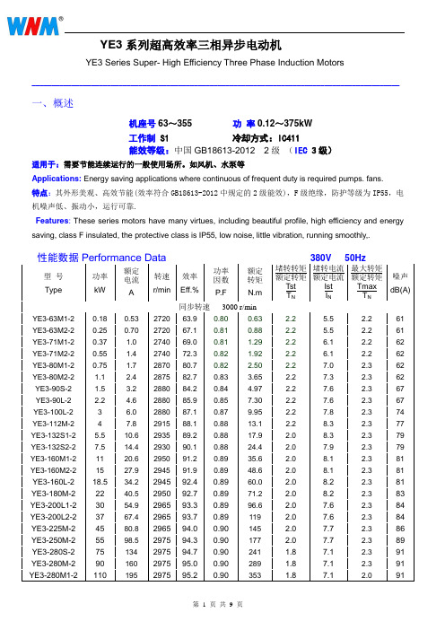
YE3系列超高效率三相异步电动机YE3 Series Super- High Efficiency Three Phase Induction Motors--------------------------------------------------------------------------------------------- 一、概述机座号63~355 功率0.12~375kW工作制 S1 冷却方式:IC411能效等级:中国GB18613-2012 2级(IEC 3级)适用于:需要节能连续运行的一般使用场所。
如风机、水泵等Applications: Energy saving applications where continuous of frequent duty is required pumps. fans.特点:其外形美观、高效节能(效率符合GB18613-2012中规定的2级能效),F级绝缘,防护等级为IP55,电机噪声低、振动小,运行可靠.Features: These series motors have many virtues, including beautiful profile, high efficiency and energy saving, class F insulated, the protective class is IP55, low noise, little vibration, running smoothly,.性能数据Performance Data型号Type 功率kW额定电流A转速r/min效率Eff.%功率因数P.F额定转矩N.m堵转转矩额定转矩TstT N堵转电流额定电流IstI N最大转矩额定转矩TmaxT N噪声dB(A)同步转速3000 r/minYE3-63M1-2 0.18 0.53 2720 63.9 0.80 0.63 2.2 5.5 2.2 61 YE3-63M2-2 0.25 0.70 2720 67.1 0.81 0.88 2.2 5.5 2.2 61 YE3-71M1-2 0.37 1.0 2740 69.0 0.81 1.29 2.2 6.1 2.2 62 YE3-71M2-2 0.55 1.4 2740 72.3 0.82 1.92 2.2 6.1 2.2 62 YE3-80M1-2 0.75 1.7 2870 80.7 0.82 2.50 2.2 7.0 2.3 62 YE3-80M2-2 1.1 2.4 2875 82.7 0.83 3.65 2.2 7.3 2.362 YE3-90S-2 1.5 3.2 2880 84.2 0.84 4.97 2.2 7.6 2.367 YE3-90L-2 2.2 4.6 2880 85.9 0.85 7.30 2.2 7.6 2.367 YE3-100L-2 3 6.0 2880 87.1 0.87 9.95 2.2 7.8 2.374 YE3-112M-2 4 7.8 2915 88.1 0.88 13.1 2.2 8.3 2.377 YE3-132S1-2 5.5 10.6 2935 89.2 0.88 17.9 2.0 8.3 2.379 YE3-132S2-2 7.5 14.4 2930 90.1 0.88 24.4 2.0 7.9 2.379 YE3-160M1-2 11 20.6 2950 91.2 0.89 35.6 2.0 8.1 2.381 YE3-160M2-2 15 27.9 2945 91.9 0.89 48.6 2.0 8.1 2.381 YE3-160L-2 18.5 34.2 2945 92.4 0.89 60.0 2.0 8.2 2.381 YE3-180M-2 22 40.5 2950 92.7 0.89 71.2 2.0 8.2 2.383 YE3-200L1-2 30 54.9 2965 93.3 0.89 96.6 2.0 7.6 2.384 YE3-200L2-2 37 67.4 2965 93.7 0.89 119 2.0 7.6 2.384 YE3-225M-2 45 80.8 2965 94.0 0.90 145 2.0 7.7 2.386 YE3-250M-2 55 98.5 2975 94.3 0.90 177 2.0 7.7 2.389 YE3-280S-2 75 134 2975 94.7 0.90 241 1.8 7.1 2.391 YE3-280M-2 90 160 2975 95.0 0.90 289 1.8 7.1 2.391性能数据Performance Data380V 50Hz型号Type 功率kW额定电流A转速r/min效率Eff.%功率因数P.F额定转矩N.m堵转转矩额定转矩TstT N堵转电流额定电流IstI N最大转矩额定转矩TmaxT N噪声dB(A)同步转速3000 r/minYE3-315S-2 110 195 2985 95.2 0.90 352 1.8 7.1 2.392 YE3-315M-2 132 234 2985 95.4 0.90 422 1.8 7.1 2.392 YE3-315L1-2 160 279 2985 95.6 0.91 512 1.8 7.2 2.392 YE3-315L-2 185 323 2985 95.7 0.91 592 1.8 7.2 2.3 92 YE3-315L2-2 200 349 2985 95.8 0.91 640 1.8 7.2 2.2 92 YE3-315L3-2 220 383 2985 95.8 0.91 704 1.8 7.2 2.2 92 YE3-355M1-2 220 383 2985 95.8 0.91 704 1.8 7.2 2.2 100 YE3-355M-2 250 436 2985 95.8 0.91 800 1.6 7.2 2.2100 YE3-355L1-2 280 488 2985 95.8 0.91 896 1.6 7.2 2.2 100 YE3-355L-2 315 549 2985 95.8 0.91 1008 1.6 7.2 2.2100 YE3-355L2-2 355 619 2985 95.8 0.91 1136 1.6 7.2 2.2 100 YE3-355L3-2 375 654 2985 95.8 0.91 1200 1.6 7.2 2.2 100同步转速1500 r/minYE3-63M1-4 0.12 0.45 1310 55.8 0.72 0.87 2.1 4.4 2.2 52 YE3-63M2-4 0.18 0.64 1310 58.6 0.73 1.31 2.1 4.4 2.2 52 YE3-71M1-4 0.25 0.81 1330 63.6 0.74 1.80 2.1 5.2 2.2 55 YE3-71M2-4 0.37 1.1 1330 65.3 0.75 2.66 2.1 5.2 2.2 55 YE3-80M1-4 0.55 1.4 1430 80.6 0.75 3.67 2.3 6.5 2.3 56 YE3-80M2-4 0.75 1.8 1430 82.5 0.75 5.01 2.3 6.6 2.3 56 YE3-90S-4 1.1 2.6 1430 84.1 0.76 7.35 2.3 6.8 2.359 YE3-90L-4 1.5 3.5 1430 85.3 0.77 10.0 2.3 7.0 2.359 YE3-100L1-4 2.2 4.8 1440 86.7 0.81 14.6 2.3 7.6 2.364 YE3-100L2-4 3 6.3 1440 87.7 0.82 19.9 2.3 7.6 2.364 YE3-112M-4 4 8.4 1455 88.6 0.82 26.3 2.2 7.8 2.365 YE3-132S-4 5.5 11.2 1465 89.6 0.83 35.9 2.0 7.9 2.371 YE3-132M-4 7.5 15.0 1465 90.4 0.84 48.9 2.0 7.5 2.371 YE3-160M-4 11 21.5 1470 91.4 0.85 71.5 2.0 7.7 2.373 YE3-160L-4 15 28.8 1470 92.1 0.86 97.4 2.0 7.8 2.373 YE3-180M-4 18.5 35.3 1470 92.6 0.86 120 2.0 7.8 2.376 YE3-180L-4 22 41.8 1470 93.0 0.86 143 2.0 7.8 2.376 YE3-200L-4 30 56.6 1475 93.6 0.86 194 2.0 7.3 2.376 YE3-225S-4 37 69.6 1480 93.9 0.86 239 2.0 7.4 2.378 YE3-225M-4 45 84.4 1480 94.2 0.86 290 2.0 7.4 2.378 YE3-250M-4 55 103 1485 94.6 0.86 354 2.0 7.4 2.379 YE3-280S-4 75 136 1490 95.0 0.88 481 2.0 6.7 2.380 YE3-280M-4 90 163 1490 95.2 0.88 577 2.0 6.9 2.380 YE3-280M1-4 110 197 1490 95.4 0.89 705 2.0 7.0 2.3 80 YE3-315S-4 110 197 1490 95.4 0.89 705 2.0 7.0 2.2 88 YE3-315M-4 132 236 1490 95.6 0.89 846 2.0 7.0 2.2 88 YE3-315L1-4 160 285 1490 95.8 0.89 1026 2.0 7.1 2.2 88 YE3-315L-4 185 329 1490 95.9 0.89 1186 2.0 7.1 2.2 88性能数据Performance Data型号Type 功率kW额定电流A转速r/min效率Eff.%功率因数P.F额定转矩N.m堵转转矩额定转矩TstT N堵转电流额定电流IstI N最大转矩额定转矩TmaxT N噪声dB(A)同步转速1500 r/minYE3-355M1-4 220 387 1490 96.0 0.90 1410 2.0 7.1 2.2 95 YE3-355M-4 250 440 1495 96.0 0.90 1597 2.0 7.1 2.2 95 YE3-355L1-4 280 492 1495 96.0 0.90 1789 2.0 7.1 2.2 95 YE3-355L-4 315 554 1495 96.0 0.90 2012 2.0 7.1 2.2 95 YE3-355L2-4 355 638 1495 96.0 0.88 2268 1.7 7.0 2.2 95 YE3-355L3-4 375 674 1495 96.0 0.88 2395 1.7 7.0 2.2 95同步转速1000 r/minYE3-71M1-6 0.18 0.76 850 54.6 0.66 2.02 1.9 4.0 2.0 52 YE3-71M2-6 0.25 0.97 850 57.4 0.68 2.81 1.9 4.0 2.0 52 YE3-80M1-6 0.37 1.2 910 68.0 0.70 3.88 1.9 5.5 2.0 54 YE3-80M2-6 0.55 1.6 925 72.0 0.71 5.68 1.9 5.8 2.1 54 YE3-90S-6 0.75 2.0 945 78.9 0.71 7.58 2.0 6.0 2.1 57 YE3-90L-6 1.1 2.8 950 81.0 0.73 11.1 2.0 6.0 2.157 YE3-100L-6 1.5 3.8 950 82.5 0.73 15.1 2.0 6.5 2.161 YE3-112M-6 2.2 5.4 965 84.3 0.74 21.8 2.0 6.6 2.165 YE3-132S-6 3 7.2 975 85.6 0.74 29.4 1.9 6.8 2.169 YE3-132M1-6 4 9.5 975 86.8 0.74 39.2 1.9 6.8 2.169 YE3-132M2-6 5.5 12.7 975 88.0 0.75 53.9 1.9 7.0 2.169 YE3-160M-6 7.5 16.2 980 89.1 0.79 73.1 1.97.0 2.170 YE3-160L-6 11 23.1 980 90.3 0.80 107 1.97.2 2.170 YE3-180L-6 15 30.9 980 91.2 0.81 146 1.97.3 2.173 YE3-200L1-6 18.5 37.8 985 91.7 0.81 179 1.97.3 2.173 YE3-200L2-6 22 44.8 985 92.2 0.81 213 1.97.4 2.173 YE3-225M-6 30 59.1 985 92.9 0.83 291 1.9 6.9 2.174 YE3-250M-6 37 71.7 985 93.3 0.84 359 1.97.1 2.1 76 YE3-280S-6 45 85.8 990 93.7 0.85 434 1.97.3 2.078 YE3-280M-6 55 103 990 94.1 0.86 531 1.97.3 2.078 YE3-280M1-6 75 143 990 94.6 0.84 723 1.9 7.3 2.0 78 YE3-315S-6 75 143 990 94.6 0.84 723 1.9 6.6 2.083 YE3-315M-6 90 170 990 94.9 0.85 868 1.9 6.7 2.083 YE3-315L1-6 110 207 990 95.1 0.85 1061 1.9 6.7 2.083 YE3-315L2-6 132 244 990 95.4 0.86 1273 1.9 6.8 2.083 YE3-315L3-6 160 296 990 95.6 0.86 1543 1.9 6.8 2.0 83 YE3-355M1-6 160 296 995 95.6 0.86 1536 1.9 6.8 2.085 YE3-355M-6 185 342 995 95.7 0.86 1776 1.9 6.8 2.0 85 YE3-355M2-6 200 365 995 95.8 0.87 1920 1.9 6.8 2.085 YE3-355L1-6 220 401 995 95.8 0.87 2112 1.9 6.8 2.0 85 YE3-355L-6 250 456 995 95.8 0.87 2399 1.9 6.8 2.085 YE3-355L2-6 280 510 995 95.8 0.87 2687 1.9 6.8 2.0 85 YE3-355L3-6 315 581 995 95.8 0.86 3023 1.9 6.8 2.0 85性能数据Performance Data380V 50Hz型号Type 功率kW额定电流A转速r/min效率Eff.%功率因数P.F额定转矩N.m堵转转矩额定转矩TstT N堵转电流额定电流IstI N最大转矩额定转矩TmaxT N噪声dB(A)同步转速750 r/minYE3-80M1-8 0.18 0.80 700 56.0 0.61 2.46 1.8 3.3 1.9 52 YE3-80M2-8 0.25 1.1 700 59.0 0.61 3.41 1.8 3.3 1.9 52 YE3-90S-8 0.37 1.4 695 66.0 0.61 5.08 1.8 4.0 1.9 56 YE3-90L-8 0.55 2.0 695 70.0 0.61 7.56 1.8 4.0 2.0 56 YE3-100L1-8 0.75 2.3 705 73.5 0.67 10.2 1.8 4.0 2.0 59 YE3-100L2-8 1.1 3.2 705 76.5 0.69 14.9 1.8 5.0 2.0 59 YE3-112M-8 1.5 4.2 715 77.5 0.70 20.0 1.8 5.0 2.0 61 YE3-132S-8 2.2 5.9 730 80.0 0.71 28.8 1.8 6.0 2.2 64 YE3-132M-8 3 7.6 730 82.5 0.73 39.2 1.8 6.0 2.2 64 YE3-160M1-8 4 9.8 725 85.0 0.73 52.7 1.9 6.0 2.2 68 YE3-160M2-8 5.5 13.1 725 86.0 0.74 72.4 1.9 6.0 2.2 68 YE3-160L-8 7.5 17.4 730 87.5 0.75 98.1 1.9 6.0 2.2 68 YE3-180L-8 11 25.0 725 89.0 0.75 145 1.9 6.5 2.2 70 YE3-200L-8 15 33.2 730 90.4 0.76 196 2.0 6.6 2.2 73 YE3-225S-8 18.5 40.6 735 91.2 0.76 240 2.0 6.6 2.2 73 YE3-225M-8 22 46.8 735 91.5 0.78 286 2.0 6.6 2.2 73 YE3-250M-8 30 62.6 735 92.2 0.79 390 1.9 6.5 2.0 75 YE3-280S-8 37 76.5 740 93.0 0.79 478 1.8 6.6 2.0 76 YE3-280M-8 45 92.6 740 93.5 0.79 581 1.8 6.6 2.0 76 YE3-315S-8 55 110 740 93.8 0.81 710 1.8 6.6 2.0 82 YE3-315M-8 75 150 740 94.0 0.81 968 1.8 6.2 2.0 82 YE3-315L1-8 90 176 740 94.5 0.82 1161 1.8 6.4 2.0 82 YE3-315L2-8 110 215 740 94.8 0.82 1420 1.8 6.4 2.0 82 YE3-355M1-8 132 257 745 95.0 0.82 1692 1.8 6.4 2.0 90 YE3-355M2-8 160 312 745 95.0 0.82 2051 1.8 6.4 2.0 90 YE3-355L1-8 185 360 745 95.2 0.82 2371 1.8 6.4 2.0 90 YE3-355L-8 200 385 745 95.2 0.83 2564 1.8 6.4 2.0 90 YE3-355L2-8 220 423 745 95.2 0.83 2820 1.8 6.4 2.0 90 YE3-355L3-8 250 481 745 95.2 0.83 3205 1.8 6.5 2.0 90同步转速600 r/minYE3-315S-10 45 99 590 92.0 0.75 728 1.5 6.2 2.0 90 YE3-315M-10 55 120 590 92.5 0.75 890 1.5 6.2 2.0 90 YE3-315L1-10 75 161 590 93.0 0.76 1214 1.5 5.8 2.0 90 YE3-315L2-10 90 190 590 93.4 0.77 1457 1.5 5.9 2.0 90 YE3-355M1-10 110 228 595 93.8 0.78 1766 1.3 6.0 2.0 90 YE3-355M2-10 132 273 595 94.2 0.78 2119 1.3 6.0 2.0 90 YE3-355L1-10 160 331 595 94.2 0.78 2568 1.3 6.0 2.0 90 YE3-355L-10 185 383 595 94.2 0.78 2969 1.3 6.0 2.0 90 YE3-355L2-10 200 414 595 94.2 0.78 3210 1.3 6.0 2.0 90外形及安装尺寸 Dimensions mm B14 (机座无底脚、端盖上有小凸缘)机座号Frame 极数Poles 安 装 尺 寸 及 公 差 Mounting Dimension 外 形 尺 寸 Overall Dimension D E F G M N P R S T AC AD HF L 63M 2,4 11 23 4 8.5 75 60 90 0 4-M5 2.5 135 70 140 230 71M 2,4,6 14 30 5 11 85 70 105 0 4-M6 2.5 145 80 160 255 80M 2,4,6,8 19 40 6 15.5 100 80 120 0 4-M6 3 165 145 245 295 90S 2,4,6,8 24 50 8 20 115 95 140 0 4-M8 3 180 165 265 345 90L2,4,6,8385 100L 2,4,6,8 28 60 8 24 130 110 160 0 4-M8 3.5 205 175 300 390 112M2, 6,8 28608241301101604-M83.52251903154204450B34 (机座带底脚、端盖上有小凸缘)机座号 Frame 极数 Poles 安 装 尺 寸 及 公 差 Mounting Dimension 外 形 尺 寸 Overall Dimension ABCDEF GH K MNPRSTAA BB HA AB AC AD HDL63M 2,4100 80 40 11 23 4 8.5 63 7 75 60 90 0 4-M5 2.5 30 110 8 135 135 70 180 230 71M2,4,6 112 90 45 14 3051171 7 85 70 105 04-M6 2.5 32 120 8 150 145 80 195 255 80M 2,4,6,8 125 100 50 19 40 6 15.5 80 10 100 80 120 0 4-M6 3 32 135 10 160 165 145 225 295 90S 2,4,6,8 140100 56 24 508 2090 10 115 95 140 04-M8334170 12 180 180 165 255345 90L2,4,6,8125210385100L 2,4,6,8 160 140 63 28 60 8 24 100 12 130 110 160 0 4-M8 3.5 39 186 14 200 205 175 275 390 112M2, 6,8 190 140 70 28 60824 112 12 130 110 160 04-M8 3.5 45200 14 230 225 190 300420 4230450外形及安装尺寸Dimensions mm B3(机座带底脚、端盖无凸缘)机座号Frame极数Poles安装尺寸Mounting Dimension 外形尺寸Overall DimensionA B C D E F G H K AA BB HA AB AC AD HD L63M 2,4 100 80 40 11 23 4 8.5 63 7 30 110 8 135 135 70 180 230 71M 2,4,6 112 90 45 14 30 5 11 71 7 32 120 8 150 145 80 195 255 80M 2,4,6,8 125 100 50 19 40 6 15.5 80 10 32 135 10 160 165 145 225 29590S2,4,6,8 140 10056 24 50 8 20 90 10 3417012 180 180 165 25534590L 125 210 385 100L 2,4,6,8 160 140 63 28 60 8 24 100 12 39 186 14 200 205 175 275 390112M 2, 6,8190 140 70 28 60 8 24 112 12 4520014 230 225 190 300420 4 230 450132S2,4,6,8 216 14089 38 80 10 33 132 12 5519018 265 270 220 350465132M 178 230 505160M2,4,6,8 254 210108 42 110 12 37 160 15 6526020 315 320 260 420610160L 254 304 650180M2,4,6,8 279 241121 48 110 14 42.5 180 15 7031122 355 360 265 445685180L 279 349 725 200L 2,4,6,8 318 305 133 55 110 16 49 200 19 74 379 26 395 400 305 505 775225S 4,8356 28614960 140 18 53225 19 7837528 435 450 325 550815225M231155 110 16 49400810 4,6,8 60 140 18 53 840250M2406 349 16860140 1853250 24 80 445 30 490 510 380 630 920 4,6,8 65 58280S2457 3681906514018 58280 24 9048535 545 550 395 6759654,6,8 75 20 67.5280M241965 18 58536 1015 4,6,8 75 20 67.5315S2508 40621665 140 18 58315 28 12057045 635 630 540 85511804,6,8,10 80 170 22 71 1210315M245765 140 18 586101215 4,6,8,10 80 170 22 71 1245315L250865 140 18 586801290 4,6,8,10 80 170 22 71 1320355M2610 56025475 140 20 67.5355 28 13069052 735 715 645 100013904,6,8,10 95 170 25 86 1420355L/L12630 75 140 20 67.575015004,6,8,10 95 170 25 86 1530 355L2/L32 80 170 22 71 1530外形及安装尺寸Dimensions mm B5(机座不带底脚、端盖有凸缘)机座号Frame极数Poles安装尺寸及公差Mounting Dimension 外形尺寸Overall DimensionD E F G M N P R S T AC AD HF L63M 2,4 11 23 4 8.5 115 95 140 0 4-Φ10 3 135 70 140 230 71M 2,4,6 14 30 5 11 130 110 160 0 4-Φ10 3.5 145 80 160 255 80M 2,4,6,8 19 40 6 15.5 165 130 200 0 4-Φ12 3.5 165 145 245 29590S2,4,6,8 24 50 8 20 165 130 200 0 4-Φ12 3.5 180 165 265 34590L 385 100L 2,4,6,8 28 60 8 24 215 180 250 0 4-Φ15 4 205 175 300 390112M 2,6,828 60 8 24 215 180 250 0 4-Φ15 4 225 190 315420 4 450132S2,4,6,8 38 80 10 33 265 230 300 0 4-Φ15 4 270 220 370 465132M 505160M2,4,6,8 42 110 12 37 300 250 350 0 4-Φ19 5 320 260 435 610160L 650180M2,4,6,8 48 110 14 42.5 300 250 350 0 4-Φ19 5 360 265 440 685180L 725 200L 2,4,6,8 55 110 16 49 350 300 400 0 4-Φ19 5 400 305 505 775225S 4,8 60 140 18 53400 350 450 0 8-Φ19 5 450 325 550 815225M2 55 110 16 49 810 4,6,8 60 140 18 53 840250M2 60140 1853500 450 550 0 8-Φ19 5 510 380 655 920 4,6,8 65 58280S2 65140 18 58500 450 550 0 8-Φ19 5 550 395 6709654,6,8 75 20 67.5280M2 65 18 581015 4,6,8 75 20 67.5外形及安装尺 Dimensions mm B35(机座带底脚、端盖有凸缘)机座号Frame极数Poles安装尺寸及公差Mounting Dimension 外形尺寸Overall DimensionA B C D E F G H K M N P R S T AA BB HA AB AC AD HD L63M 2,4 100 80 40 11 23 4 8.5 63 7 115 95 140 0 4-Φ10 3 30 110 8 135 135 70 180 230 71M 2,4,6 112 90 45 14 30 5 11 71 7 130 110 160 0 4-Φ10 3.5 32 120 8 150 145 80 195 255 80M 2,4,6,8 125 100 50 19 40 6 15.5 80 10 165 130 200 0 4-Φ12 3.5 32 135 10 160 165 145 225 29590S2,4,6,8 140 10056 24 50 8 20 90 10 165 130 200 0 4-Φ12 3.5 3417012 180 180 165 25534590L 125 210 385100L 2,4,6,8 160 140 63 28 60 8 24 100 12 215 180 250 0 4-Φ15 4 39 18614 200 205 175 275 390112M 2,6,8190 140 70 28 60 8 24 112 12 215 180 250 0 4-Φ15 4 45200230 225 190 300420 4 230 450132S2,4,6,8 216 14089 38 80 10 33 132 12 265 230 300 0 4-Φ15 4 5519018 265 270 220 350465132M 178 230 505160M2,4,6,8 254 210108 42 110 12 37 160 15 300 250 350 0 4-Φ19 5 6526020 315 320 260 420610160L 254 304 650180M2,4,6,8 279 241121 48 110 14 42.5 180 15 300 250 350 0 4-Φ19 5 7031122 355 360 265 445685180L 279 349 725 200L 2,4,6,8 318 305 133 55 110 16 49 200 19 350 300 400 0 4-Φ19 5 74 379 26 395 400 305 505 775225S 4,8356 28614960 140 18 53225 19 400 350 450 0 8-Φ19 5 7837528 435 450 325 550815225M231155 110 16 49400810 4, 6,8 60 1401853840250M2406 349 16860140 250 24 500 450 550 0 8-Φ19 5 80 445 30 490 510 380 630 920 4, 6,8 6558280S2457 36819065140 280 24 500 450 550 0 8-Φ19 5 9048535 545 550 395 6759654, 6,8 75 20 67.5280M241965 18 58536 1015 4, 6,8 75 20 67.5315S2508 40621665 140 18 58315 28 600 550 660 0 8-Φ24 6 12057045 635 630 540 85511804,6,8,10 80 170 22 71 1210315M245765 140 18 586101215 4,6,8,10 80 170 22 71 1245315L250865 140 18 586801290 4,6,8,10 80 170 22 71 1320355M2610 56025475 140 20 67.5355 28 740 680 800 0 8-Φ24 6 13069052 735 715 645 100013904,6,8,10 95 170 25 86 1420355L/L12630 75 140 20 67.575015004,6,8,10 95 170 25 86 1530外形及安装尺寸Dimensions mm V1(立式安装、机座不带底脚、端盖有凸缘、轴伸向下的电动机)机座号Frame极数Poles安装尺寸Mounting Dimension 外形尺寸Overall DimensionD E F G M N P R S T AC AD HF L180M2,4,6,8 48 110 14 42.5 300 250 350 0 4-Φ19 5 360 265 500 745180L 785 200L 2,4,6,8 55 110 16 49 350 300 400 0 4-Φ19 5 400 305 570 845225S 4,8 60 140 18 53400 350 450 0 8-Φ19 5 450 325 615 905225M2 55 110 16 49 900 4,6,8 60 140 18 53 930250M2 60140 1853500 450 550 0 8-Φ19 5 510 380 715 1025 4,6,8 65 58280S2 65140 18 58500 450 550 0 8-Φ19 5 550 395 76010804,6,8 75 20 67.5280M2 65 18 581130 4,6,8 75 20 67.5315S2 65 140 18 58600 550 660 0 8-Φ24 6 630 540 970 13104,6,8,10 80 170 22 71 1340315M2 65 140 18 58 1345 4,6,8,10 80 170 22 71 1375315L2 65 140 18 58 1420 4,6,8,10 80 170 22 71 1450355M2 75 140 20 67.5740 680 800 0 8-Φ24 6 715 645 1135 15304,6,8,10 95 170 25 86 1560355L/L12 75 140 20 67.5 1640 4,6,8,10 95 170 25 86 1670355L2/L32 80 170 22 71 1670 4,6,8,10 110 210 28 100 1710Conventional mounting type and suitable frame size are given in following table(with “√”)机座号Frame基本安装结构basic type派生的安装形式derived typeB3 B5 B35 V1 V3 V5 V6 B6 B7 B8 V15 V36 B14 B34 V1863~112 √√√√√√√√√√√√√√√132~160 √√√√√√√√√√√√- - - 180~280 √√√√- - - - - - - - - - -。
低压电机中英文对照说明书
to check free rotation.
绝缘电阻检查
Insulation resistance check
在电机调试前或怀疑线圈受潮时要测量电机的绝缘电阻,在25℃时的电阻值应超过以下表达式的值,表 达式中:
Measure insulation resistance before commissioning and when winding dampness
度下烘12-16小时再在105℃下烘6-8小时。
WARNING
Windings should be discharged immediately after measurement to avoid risk for
1
OEHB.460.002 低压电机使用维护说明书
electric shock. Insulation resistance reference value is halved for each 20°C rise in ambient temperature. If the reference resistance value is not attained, the winding is too damp and must be oven dried. Oven temperature should be 90°C for 12-16 hours followed by 105°C for 6-8 hours.
The variable speed motor starts at low-speed status and then shifted to high-speed. For varible speed motor with many sets of windings, the speed shift shall be fulfilled when one winding has lost power.
- 1、下载文档前请自行甄别文档内容的完整性,平台不提供额外的编辑、内容补充、找答案等附加服务。
- 2、"仅部分预览"的文档,不可在线预览部分如存在完整性等问题,可反馈申请退款(可完整预览的文档不适用该条件!)。
- 3、如文档侵犯您的权益,请联系客服反馈,我们会尽快为您处理(人工客服工作时间:9:00-18:30)。
Y2 系列
三相异步电动机
使用维护说明书安徽皖南电机股份有限公司
衷心感谢您选购、使用南华牌电动机
在使用电动机之前,请仔细阅读本说明书,以便您正确的使用和维护。
检查
1.仔细检查电动机外观是否损伤,核对电动机铭牌数据,如型号、额定功率、电压、频率等与实际要求是否相符。
2.轻轻传动电动机转轴。
转动应轻快、灵活(注:装有骨架式橡胶油封的IP55电动机转动时相对较紧)。
3.检查零部件的装配应良好,紧固件应无松动。
4.打开接线盒,用500V兆欧表测量电动机绕组的绝缘电阻,所测值应不低于5兆欧。
注意:检查过程中,若有疑问,应向专业技术人员请教或与我们联系。
安装
电动机的安装应由技术人员完成,对带底脚的电动机,安装平面应坚固,并保证底脚在一个平面上。
如果底脚要加垫片,应保证在电动机底脚安装
紧固过程中不被挤出。
电动机允许采用联轴器、正齿轮及皮带轮传动。
联接电动机的电源线不宜过细、过长,否则电源线压降过大,使电动机起动困难)。
按接线图,将电源线与电动机牢固联接,同时接好接地线。
在接通电源前,还应测量输入电压是否正确,然后接通电源,检查旋转转速,旋转方向是否正确。
运行与维护
1.电动机使用的环境最高温度为40℃,最低温度为-15℃,海拔不超过1000m。
2.电动机允许满压或降压起动,但应注意,满压起动时起动电流为额定电流的3.3~7.5倍。
降压起动时,因转矩与电压的平方成正比,电压下降时转矩也随之降低。
故当静负荷相当大时只能用满压起动。
3.电动机不得用于含有易燃性气体、化学腐蚀性气体或其它有害气体的
环境中(特殊环境用电动机除外)。
4.电动机必须保持清洁,进风口及风道必须畅通无阻。
5.电动机在运行中若发现异常,如怪声、过热、焦味或轴承发热等,应立即停机检查,待故障排除后方可使用。
6.电动机在运行过程中应保证润滑良好,一般在电机运行5000小时左右,即应更换润滑脂(封闭轴承在使用寿命期内不必更换润滑脂)。
在运行中若发现轴承过热时,应停机检查轴承润滑脂是否太多。
油脂添加量以加油到轴承容腔的1/3~1/2左右为宜。
润滑脂推荐采用ZI.3锂基润滑脂小型电动机专用润滑脂。
7.为保证电动机的正常运行,应根据实际使用情况对电动机进行定期检查,并需每年检修一次。
8.电动机在仓库中搁置不用时,应妥善包装、存放,并保持通风干燥,以免电机受潮,锈蚀。
注意:不要在电动机运行时添加润滑脂,过多的润滑脂会溢出,并可能附着到定子绕组上,使其绝缘寿命降低,同时使轴承工作温度升高(轴承工作温度不超过90℃)。
在用户按照本使用维护说明书的规定,正确地使用与存放电动机的情况下,本公司保证电动机在使用的一年内,或自本公司起运的日期不超过二年的时间内能良好运行。
对于人为因素或偶然事故性的故障本公司不负责免费维修。
销售处:(0563)5031908
客户服务中心:(0563)5031953
企业管理处:(0563)5031954
质量检验处:(0563)5031910
传真:(0563)5029999 5023608
地址:安徽省泾县南华路86号
E-mail:wndjc@
邮政编码:242500。