ex005
诺雅克产品快速选型

251000Contents 目录25~47终端类Ex9PN 系列小型断路器(相线+中性线)Ex9BD 系列直流小型断路器Ex9BP 系列光伏专用直流小型断路器Ex9LE 剩余电流动作附件Ex9PLE 剩余电流动作保护断路器Ex9I 系列隔离开关Ex9F 系列熔断器Ex9U 系列电涌保护器Ex9B 系列小型断路器Ex9BM 系列小型断路器48~6667~6970~73控制类箱体类智能仪表Ex9Ci 系列低功耗交流接触器Ex9R 系列热过载继电器Ex9RC 系列中间继电器Ex9CC 系列电容接触器Ex9QC 系列电磁起动器Ex9QS 系列星--三角电磁起动器NEV 直流继电器Ex9C 系列交流接触器光伏汇流箱SUP 监控装置PMR700智能电动机保护器PMA700智能电力参数测量仪01~24配电类Ex9A 系列空气断路器Ex9M 系列塑壳断路器ExATS 系列自动转换开关019A16、9A32、9A40选型说明空气断路器Ex9A Ex9A 3P 产品代号极数代号16:1600A32:3200A40:4000A 16:1600A,1250A,1000A,800A,630A,400A 32:3200A,2900A,2500A,2000A,1600A 40:4000A,3200A,2900A,2500A,2000A Smart Unit 智能控制器SU30A:电流型30A SU40A:电流型40A SU50A:电流型5.0A SU30D:电压型30D SU40D:电压型40D SU50D:电压型50D SU30P:电能型30P SU40P:电能型40P SU50P:电能型50P SU30H:谐波型30HSU40H:谐波型40HSU50H:谐波型50HSU30GP:发电机电能型30GP SU30GH:发电机谐波型30GP AC230:交流230V AC400:交流400VDC220:直流220VDC110:直流110VDC24:直流24V N:55kA Q:65kA R:85kA H:100kA 9A16可选N 、Q 9A32可选Q 、R 、H 9A40可选Q 、R 、H 3P :三极4P :四极D/O :抽屉式(可省略)F :固定式无特殊要求此处无代号有特殊要求根据要求适时指定代号壳架等级额定电流代号额定电流代号智能控制器代号控制回路电源电压代号分断能力代号安装方式代号特殊要求代号161600SU 30A AC230N D/O OTHER 选型举例:“Ex9A16 3P 1250 F SU40P AC230”的含义为Ex9A 系列1600壳架的、三极的、1250A 的、固定式的、带多功能电能型4.0P 控制器的、控制回路电源电压为交流230V 的空气断路器。
IECEx国际电工委员会防爆电气产品认证体系介绍

IECEx国际电工委员会防爆电气产品认证体系介绍文章来源:中国防爆网发布时间:2006-6-2 点击次数:8814国际电工委员会防爆电气产品认证体系 (以下简称 IECEx 认证体系)成立于 1996年,是国际性的防爆电气产品防爆认证组织。
IECE x 认证体系是国际电工委员会合格评定局(CAB)下设的 3 个产品认证组织之一,与其并列的还有电工电子产品认证( IECEE )和电子元件产品合格评定( IECQ )。
IECEx 认证体系的宗旨是建立防爆电气产品国际认证体系,促进国际贸易。
其最终目标是实现防爆电气产品在全世界范围内实现统一标准,统一证书,统一标志。
IECEx认证体系目前已经有正式成员国22个,其中包括欧、美、澳洲的主要工业国家以及俄罗斯、韩国等国,我国是IECEx认证体系的正式成员国,参加IECEx的国家成员为国家认监委(CNCA)。
IECEx体系接受的认证机构(ExCB)和检验实验室(ExTL)才能从事IECEx体系的认证工作。
经CNCA推荐,中国参加IECEx的认证机构是方圆标志认证中心(CQM),检验实验室是国家防爆电气产品质检中心、上海仪器仪表自控系统测试所、石油化工防爆质检中心和国家煤矿防爆安全产品质检中心。
按照IECEx秘书处的计划安排,CQM和上述检验实验室即将接受IECEx体系的国际同行评审,被IECEx体系接受为ExCB和ExTL后,可以为我国广大的防爆电气产品生产企业提供防爆电气产品国际认证和产品检验服务。
防爆电气设备专门用于石油、化工、煤矿、轻纺、粮食加工以及军工等工业部门中可能出现或聚集爆炸性气体、蒸气、粉尘或纤维等物料的爆炸危险场所,主要品种有防爆电动机、防爆开关电器、防爆灯具、防爆仪表、成套设备和附件等。
IECEx认证体系采用国际上通用的第五种认证模式,即型式检验 +工厂质量体系审核 + 认证后监督,认证依据的标准是IEC制订的爆炸危险环境用电气设备系列标准,其标准代号为IEC60079( 爆炸性气体环境用电气设备)和IEC61241(可燃性粉尘环境用电气设备)。
富山电脑缝纫机hp-005款电控资料
富山HP-005伺服控制器安装维护手册本手册仅提供给技术支持、售后、维修使用。
文中所涉及的内容,是按最新版本软件编写。
如有和控制箱本身说明不符的地方,一律以控制箱本身的说明为准,在实际的维护过程中,可能会碰到文中没有提到的内容,请及时向公司有关部分反馈,尽可能的在下一版本中,将新发现的问题一一列出。
文中所提供的资料仅供参考,具体以实物的规格书为准!(仅供内部使用参考)目录0、主要技术数据: (4)1、安全注意事项: (5)1.1 使用范围: (5)1.2 工作环境: (5)1.3 安装: (5)1.4 保养维修的规定: (5)1.5危险提示 (6)1.6 其它安全规定: (6)2. 安装与调整: (6)2.1 电机的安装: (6)2.2 针位信号器及手轮的安装: (7)2.3 控制箱的安装: (7)2.4 停针位的调整: (8)3. 接线与接地: (8)3.1 电源线的接法: (8)3.2、控制器接线端子图: (9)4、操作面板的使用: (10)4.1、操作面板按键定义: (10)4.2、操作面板参数设定: (11)4.3、操作面板的组合操作及显示 (15)5、主控制箱面板操作说明书 (16)5.1、主控制箱面板的布局如下示意图, (16)5.2、待机状态: (16)5.3、缝纫模式及各段针数设置: (17)5.4 前固缝方式及针数设置: (18)5.5 后固缝方式及针数设置: (18)5.6 工艺参数设置: (19)6、针迹补偿调整方法 (20)6.1 调整前的准备 (20)6.2 调整步骤 (20)7、常用参数的修改示例 (21)7.0 参数修改状态的进入方法 (21)7.1 如何修改自由缝最高速度 (21)7.2 如何修改慢启动速度 (22)7.3 如何关掉上电找停针位 (22)7.4 如何修改剪线速度 (22)7.5 如何恢复出厂参数 (22)7.6 如何修改工艺参数密码 (22)7.7 如何修改底线总数 (22)8、控制箱硬件检测方法 (23)8.1 维护参数表 (23)8.2、历史故障查询功能 (25)8.3、控制箱外围部件检测 (25)1、电机码盘的检测 (25)2、手动倒缝开关的检测 (25)3、立式脚踏的检测 (25)4、脚踏的检测 (25)9、故障分析 (26)9.1、故障代码表内故障的解决办法 (26)9.2、电磁铁故障分析 (28)1、剪线电磁铁故障的分析 (28)2、扫(挑)线电磁铁故障的分析 (28)3、倒缝电磁铁故障的分析 (28)4、手动倒缝故障的分析 (28)5、抬压脚电磁铁故障的分析 (28)9.3、部分故障问答 (29)10、出厂及维护时使用的特殊操作 (29)10.1 密码清除 (29)10.2 主控箱软件版本查询 (30)10.3 存储器数据复位 (30)10.4 机头工作时间清除 (30)10.5、厂家出厂参数的修改 (30)10.6、出厂机型参数的修改 (31)10. 7、特殊机型参数的修改 (31)11. 七段数码管显示值与实际数值对照表 (32)0、主要技术数据:供电电压范围:AC220V ±15% 供电电源频率:50Hz/60Hz 整机最大功率:700W电机额定功率:550W 电机额定转速:4500rpm 电机额定转矩:1.0Nm 电机最大转矩:3.0Nm感谢您选用本公司工业平缝机伺服控制器。
欧勒姆电气(珠海)有限公司 微型空气站说明书
欧勒姆电气(珠海)有限公司Oromë Electrical(Zhuhai)Co.,Ltd.微型空气站说明书目录一、系统概述 (1)二、主要技术参数 (2)1、微型空气站 (2)2、气体传感器 (2)3、风速传感器 (3)4、风向传感器 (4)5、气象多要素百叶箱 (4)三、产品说明 (5)1、产品结构示意图 (5)2、产品特点 (6)3、风速监测单元 (6)4、风向监测单元 (8)5、气象多要素百叶箱 (9)四、设备操作说明 (10)1、设备启动 (10)2、传感器参数设置 (11)3、MN号更改操作方法 (12)五、云平台操作方法 (13)六、设备维护 (16)七、故障处理 (16)1 / 16欧勒姆电气(珠海)有限公司Oromë Electrical (Zhuhai )Co.,Ltd.一、系统概述微型空气站是一款用于提供室外空气污染物实时监测的产品。
微型空气站是针对大气环境中常见的指数(一氧化碳、二氧化硫、二氧化氮、臭氧、PM2.5、PM10、温度、湿度、风速、风向、大气压等)进行实时数据采集, 支持 24 小时在线监测,选用当前先进的高精度四电极电化学及光学技术原理,具有响应速度快、可靠性强,维护成本低、使用寿命长等特点。
现场采集的数据发送至数据汇总云服务平台。
图 1-1 微型空气站采用节能供电,降低能耗,也可选择市电。
集成“四气两尘”(SO2、NO2、CO 、O3、PM2.5、PM10)传感器结合无线通讯技术,实现实时数据监测,将环境大数据汇集到“云平台”,为网格化平台提供数据基础;此设备体积轻小,外形美观,安装方便,可根据现场进行校准,确保其具有最佳的可追溯性。
用户可根据实地情况选择太阳能板供电或采用市电供电。
可根据自身需求对所测量的参数自定义,可选项包括:标准污染物臭氧(O3)、二氧化氮(NO2)、氮氧化物(NOx)、一氧化碳(CO)、二氧化硫(SO2)、颗粒物(PM10、PM2.5);以及温度、湿度、风速、风向、大气压等气象参数。
OX-2281-EAE-5000-20M000 OCXO 20MHz巧克力时间器说明书

OX-2281-EAE-5000-20M000OCXONominal frequency (f0)20MHzFeaturesApplication•SC Cut Crystal •hermetically sealed •SMD•S3E compliant according GR1244•Wander generation (Standard /ZLAN Group)MTIE &TDEV compliant with:-G.8272(zG1&zG2)Performance SpecificationsAbsolute Maximum Ratings ParameterMinT ypical Max Units Supply voltage (Vs) 5.5VOperable temperature range-40+85◦C Storage temperature range -40+85◦CEnclosure4567321Top ViewH 0,37,62 0,117,8 0,10,223,4 0,17,62 0,117,8 0,1PadvorschlagrecommendationG3432,52,50,082,73,4-Pad Thickness 6030 mas long as the non-Pins/Pads area is higher.If the non-Pins/Pads area is lower, it adds to the coplanarity.all units in mmSolder profileNotes:Unless otherwise stated all values are valid after warm-up time and refer to typical conditions for supply voltage, frequency control voltage,load,temperature(25◦C).Subject to technical modification.USA:Europe:100Watts Street LandstrasseMt Holly Springs,P A1706574924NeckarbischofsheimGermanyTel:1.717.486.3411T el:+49(0)7268.801.0Fax:1.717.486.5920Fax:+49(0)7268.801.281Information contained in this publication regarding device applications and the like is provided only foryour convenience and may be superseded by updates.It is your reasonability to ensure that yourapplication meets with your specifications.MICROCHIP MAKES NO REPRESENT A TION ORWARRANTIES OF ANY KIND WHETHER EXPRESS OR IMPLIED,WRITTEN OR ORAL,ST ATUTORYOR OTHERWISE,RELA TED TO THE INFORMA TION INCLUDING,BUT NOT LIMITED TO ITSCONDITION,QUALITY,PERFORMANCE,MERCHANT ABILITY OR FITNESS FOR PURPOSE.Microchip disclaims all liability arising from this information and its e of Microchip devices in lifesupport and/or safety applications is entirely at the buyer’s risk,and the buyer agrees to defend,indemnify and hold harmless Microchip from any and all damages,claims,suits,or expenses resultingfrom such use.No licenses are conveyed,implicitly,or otherwise,under any Microchip intellectualproperty rights unless otherwise statedTrademarksThe Microchip and Vectron names and logos are registered trademarks of Microchip TechnologyIncorporated in the U.S.A.and other countries.List of appendicesAppendix_OX-228-EAE-5000-20M000_Jitter II Appendix_OX-228_MTIE_TDEV III Appendix_OX-2281-EAE-5000-20M000_I2C_V1.0VII Appendix handling&processing note XIIOX-2281-EAE-5000-20M0000M000The following MTIE TDEV plots were generated from data collected on production devices over the course of a year and represent typical performance. Frequency is measured every second and converted to phase using Microchip’s golden standard TimeMonitor soft ware. Filtering is applied to the data per standards requirements, and limits where applicable, are shown in red. Additional information on standards and oscillatorrecommendations can be found in ZLAN-830 and ZLAN-3467 (formerly ZLAN-442 and ZLAN-68).Const. Temp ±1°K; slope 0,1°C/min, range 21..23°C Const. Temp ±5°F; slope 0,1°C/min,range 19.22..24.78°C Trapezoid_Pattern_slope 0,5°C/min,range +2,5...42,5°C Triangle-Pattern_slope 0,2°C/min,range -40...85°CConst. Temp ±1°K; slope 0,1°C/min, range 21..23°C Const. Temp ±5°F; slope 0,1°C/min,range 19.22..24.78°C Trapezoid_Pattern_slope 0,5°C/min,range +2,5...42,5°C Triangle-Pattern_slope 0,2°C/min,range -40...85°CConst. Temp ±1°K; slope 0,1°C/min, range 21..23°C Const. Temp ±5°F; slope 0,1°C/min,range 19.22..24.78°C Trapezoid_Pattern_slope 0,5°C/min,range +2,5...42,5°C Triangle-Pattern_slope 0,2°C/min,range -40...85°CConst. Temp ±1°K; slope 0,1°C/min, range 21..23°C Const. Temp ±5°F; slope 0,1°C/min,range 19.22..24.78°C Trapezoid_Pattern_slope 0,5°C/min,range +2,5...42,5°C Triangle-Pattern_slope 0,2°C/min,range -40...85°C2The I2C interface option is available since manufacturing DC 2301The I2C interface shall be compliant with the I2C-Bus specification for standard speed operation. I2C Bus Voltage V I2C= 3.0VI²C-Device interface (SDA, SCL) Characteristics22Following the Start condition from the master, the device code (7 bits) and the R/W bit is placed onto the bus by the master transmitter. This indicates to the addressed slave receiver that 2 bytes with a word address (little endian format) will follow once it has generated an Acknowledge bit during the ninth clock cycle. Therefore, the next 2 bytes transmitted by the master is the word address and will be written into the Address Pointer of the slave device. After receiving another Acknowledge signal from the slave device, the master device will transmit the data word to be written into the addressed memory location. The slave device acknowledges again and the master generates a Stop condition. This initiates the internal write cycle and, during this time, the slave device will not generate Acknowledge signals.AP2.2 Page write operationThe write control byte, word address and the first data byte are transmitted to the slave device in the same way as in a byte write. However, instead of generating a Stop condition, the master transmits up to 16 data bytes to the slave device, which are temporarily stored in the on chip page buffer and will be written into memory once the master has transmitted a Stop condition. Upon receipt of each word, the Address Pointer bits are internally incremented by ‘1’. As with the byte write operation, once the Stop condition is received an internal write cycle will beginAP2.3 Acknowledge pollingSince the device will not acknowledge during a write cycle, this can be used to determine when the cycle is complete (this feature can be used to maximize bus throughput). Once the Stop condition for a Write command has been issued from the master, the device initiates the internally-timed write cycle and ACK polling can then be initiated immediately. This involves the master sending a Start condition followed by the control byte for a Write command (R/W = 0). If the device is still busy with the write cycle, no ACK will be returned. If the cycle is complete, the device will return the ACK and the master can then proceed with the next Read or Write command. See the figure below for a flow diagram of this operation.AP2.4 Current address readThe slave device contains an address counter that maintains the address of the last word accessed, internally incremented by ‘1’. Therefore, if the previous access (either a read or write operation) was to address n, the next current address read operation would access data from address n + 1. Upon receipt of the slave address with R/W bit set to ‘1’, the slave device issues an acknowledge and transmits the 8-bit data word. The master willnot acknowledge the transfer, but does generate a Stop condition and the slave device discontinues transmission.AP2.5 Random readRandom read operations allow the master to access any memory location in a random manner. To perform this type of read operation, the word address must first be set. This is accomplished by sending the 2 byte word address to the slave device as part of a write operation. Once the word address is sent, the master generates a Start condition following the acknowledge. This terminates the write operation, but not before the internal Address Pointer is set. The master then issues the control byte again, but with the R/W bit set to a ‘1’. The slave device will then issue an acknowledge and transmit the 8-bit data word. The master will not acknowledge the transfer, but does generate a Stop condition and the slave device will discontinue transmission.AP2.6 Sequential readSequential reads are initiated in the same way as a random read, except that once the slave device transmits the first data byte, the master issues an acknowledge as opposed to a Stop condition in a random read. This directs the slave device to transmit the next sequentially addressed 8-bit word.ApplicationUnless otherwise noted, the products listed in the catalogue are designed for use with ordinary electrical devices, such as stationary and portable communication, control, measurement equipment etc.. They are designed and manufactured to meet a high degree of reliability (lifetime more than 15 years) under normal …commercial“ application conditions. Products dedicated for automotive and H-Rel applications are specifically identified for these applications. If you intend to use these …commercial“ products for airborne, space or critical transport applications, nuclear power control, medical devices with a direct impact on human life, or other applications which require an exceptionally high degree of reliability or safety, please contact the manufacturer.Electrostatic SensitivityCrystal oscillators are electrostatic sensitive devices. Proper handling according to the established ESD handling rules as in IEC 61340-5-1 and EN 100015-1 is mandatory to avoid degradations of the oscillator performance due to damages of the internal circuitry by electrostatics. If not otherwise stated, our oscillators meet the requirements of the Human Body Model (HBM) according to JESD22-A114F.HandlingExcessive mechanical shocks during handling as well as manual and automatic assembly have to be avoided. If the oscillator was unintentionally dropped or otherwise subject to strong shocks, please verify that the electrical function is still within specification.Improper handling may also detoriate the coplanarity of bended leads of SMD components. SolderingOscillators can be processed using conventional soldering processes such as wave soldering, convection, infrared, and vapour phase reflow soldering under normal conditions. Solderability is guaranteed for one year storage under normal climatic conditions (+5°C to +35°C @ 40% to 75% relative humidity), however typically sufficient solderability –depending on the process – is maintained also for longer time periods. In cases of doubt, components older than one year should undergo a sample solderability test.The recommended reflow solder profile for SMT componets is according IPC/JEDEC J-STD-020 (latest revision)SMD oscillators must be on the top side of the PCB during the reflow process.After reflow soldering the frequency of the products may have shifted several ppm, which relaxes after several hours or days, depending on the products. For details please contact the manufacturer.CleaningCleaning is only allowed for hermetically sealed oscillators. Devices with non hermetical enclosures (e.g. with trimmer holes) shall not be cleaned by soaking or in vapour, because residues from the cleaning process may penetrate into the interior, and degrade the performance.Our products are laser marked. The marking of our oscillators is resistant to usual solvents, such as given in IEC 60068-2-45 Test XA. For applicable test conditions see IEC 60679-1.Ultrasonic cleaning is usually not harmful to oscillators at ultrasonic frequencies of 20kHz at the sound intensities conventional in industry. Sensitive devices may suffer mechanical damage if subjected to 40kHz ultrasound at high sound pressure. In cases of doubt, please conduct tests under practical conditions with the oscillators mounted on the PC board.Hermetical SealIf the device is specified as hermetically sealed, it meets the requirements of IEC 60679-1, i.e. for enclosures with a volume smaller than 4000mm³ the leak rate is below 5*10-8 bar cm3/s, for larger enclosures it is below 1*10-6 bar c bar cm3/s, tested according to IEC 60068-2-17 Test Qk.Glass feed-throughs may be damaged as a result of mechanical overload, such as bending the connection leads or cutting them with an unappropriated tool. In order to avoid microcracking, the wire must be held fixed in position by a pressure pad between glass feed-through and the bending point during the bending process. Check: there should be no damaged edges on the glass feed-through after the bending.Tape & ReelThe packing in tape and reel is according to IEC 60286-3.Details see tape & reel data sheets.QualificationVectron products are undergoing regular qualification/reliability tests as per product family definition. Results are available upon request. Customer specific qualification tests are subject to agreement.If not otherwise stated, the product qualifications are performed according to IEC 60679-5 or other valid industry standards.ScreeningOur oscillators are 100% tested, and all key manufacturing processes are controlled by Statistical Process Control (SPC). Additional screening is therefore usually not required.On request, we can perform screening tests according to MIL-PRF-55310, class B for discrete or hybrid constructions of commercial (COTS) products. For special requirements see the High Reliability Clock section.Demounting/Desoldering of Ocsillator device for analysis:The removal or desoldering of oscillators from customer application after SMT process may cause damage to the device if not handeld appropriately. It may lead to parametric change such as frequency shift (like OCXO: up to +/- 200 ppb) . It is utmost important to minimize the direct heat exposure to the device in order to avoid such effects. Use of hot air gun for desoldering should be avoided.A mechanical stress could also destroy the part, if exposed to excessive mechanical shock after removal process. Appropriate shock protection & ESD designated packaging must be used to avoid any external mechanical shock for FA return process.In general, the products* withstand the tests listed in the following Table 1, which are based on valid industry standards.*Additional note: Test conditions could vary for different product families and individual product specifications depending on the customer as well as product requirements.Recommended Environmental Test ConditionsTable 1。
半导体光电产业用蚀刻制程化学品

顯影液
產品用途 (PURPOSE) 本產品的配方特別設計在用於彩色濾光片(CF) RGB/LED等相關電子產業光阻之顯 影,主要針對在解決RGB光阻顯影後快速將被顯影液lift off之光阻分解並且降低泡 沫,使其不會因藥液循環而導致回沾至玻璃表面因而產生殘留現象。
產品特性 (CHARACTER) eSolv DS-310 series 為AB型濃縮經濟配方,可依使用情形的不同,調配AB藥液比 例,用量節省,可大量降低成本,適用於平面顯示器製程 。 eSolv DS-305 series 為單一配方,只需以DIW稀釋即可應用至CF顯影製程上 eSolv DS-310 and DS-305顯影時線寬穩定性高,適當自動添加可使Life Time 增加 eSolv DS-310 A型成分主要為高濃度之KOH及各項親水配方
產品特性 (CHARACTER) ITO(氧化銦錫)薄膜玻璃是驅動液晶顯示器,有機發光二極體(OLED)等相關產業不可或 缺的零組件,eSolv EG-418 series產品對其蝕刻線路成形效果優良,與ITO化學反應 速度快且不傷害光阻pattern ,能避免蝕刻所造成undercut過大之情形發生,目前此 系列產品有3種, ㄧ、 EG-418 系列,此系列以王水為主,二、EG-422系列,此系 列為氯化鐵base,三、 EG-420 系列,此產品為草酸系列,兩者接可輕易完成ITO所 需蝕刻要求,除此之外,並能依據客戶需求研發針對客戶所需之ITO蝕刻液。
Al Metal Etchant
產品用途 (PURPOSE) 光電產業用導電金屬蝕刻製程化學品,適用於蝕刻鋁金屬層,利用特定鋁金屬蝕 刻液溶液(eSolv EA-855)與鋁金屬薄膜間所進行的氧化還原化學反應,去除未被 光阻覆蓋的鋁金屬,以達到鋁金屬線路成形之目的。
PEI沙伯基础
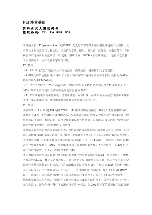
PEI沙伯基础资料由友人塑胶提供塑胶热线:TEL 136 **** ****聚醚酰亚胺(Polyetherimide,简称PEI)是无定形聚醚酰亚胺所制造的超级工程塑料,具有最佳之耐高温及尺寸稳定性,以及抗化学性、阻燃、电气性、高强度、高刚性等等,PEI 树脂可广泛应用耐高温端子,IC底座、照明设备、FPCB(软性线路板)、液体输送设备、飞机内部零件、医疗设备和家用电器等。
PEI特性:(1)PEI的特点是在高温下具有高的强度、高的刚性、耐磨性和尺寸稳定性。
(2)PEI是琥珀色透明固体,不添加任何添加剂就有固有的阻燃性和低烟度,氧指数为47%,燃烧等级为UL94-V-0级。
(3)PEI的密度为1.28~1.42g/cm3,玻璃化温度为215℃,热变形温度198~208℃,可在160~180℃下长期使用,允许间歇最高使用温度为200℃。
(4)PEI具有优良的机械强度、电绝缘性能、耐辐射性、耐高低温及耐疲劳性能和成型加工性;加入玻璃纤维、碳纤维或其他填料可达到增强改性目的。
PEI性能:主要特性:1.耐高温(HDT超过200℃,UL连续应用温度超过170℃) 2.优异的阻燃性(氧指数大于4.7,低发烟量和UL94V-0/5V) 3.不需要添加阻燃剂4.杰出的电气性能(在宽广的频率和温度范围中有稳定的介电常数和介电损耗及极高的介电强度) 5.极佳的耐化学品和耐辐射性能6.独特的强度和刚性7.透明性聚醚酰亚胺具有很宽范围的耐化学性,包括耐多数碳氢化合物、醇类和所有卤化溶剂;也可耐无机酸和短期耐弱碱。
对部分卤化溶剂,聚醚酰亚胺是良好的选材。
它的水解稳定性很好,在沸水中浸泡10 000小时后拉伸强度保持85%以上,在270F温度下,蒸汽热压循环2000次后拉伸强度保持在100%。
聚醚酰亚胺具有很好的抗紫外线、Y射线性能,在400兆拉德的钴射线辐射下加工,拉伸强度保持94%。
美国保险商实验室规定聚醚亚胺树脂的长期使用温度是338T和356T(根据等级),燃烧等级达到UL94V—0(10密耳厚度。
卓顶精文最新日本古野FURUNO-FS操作指南.doc

第一章日本古野FUYUNO FS-2570 MF/HF组合电台日本FUYUNO古野公司生产的GMDSS中频/高频(MF/HF)组合电台主要有三种型号,150W的FS-1570组合电台,250W的FS-2570组合电台和400W的FS-5000组合电台,下面以FUYUNO FS-2570 MF/HF组合电台为例介绍FUYUNO组合电台的功能。
第一节面板控制键和指示灯介绍POWEY(电源开关):开启/断开电源。
DISTYESS(遇险按钮):按住此按钮三秒以上发射遇险报警。
开始按时灯闪,大于三秒后灯亮。
收到遇险应答电报后灯灭。
如果按住此按钮少于三秒不会发射遇险报警。
CALL:发射除遇险外的呼叫。
ENTEY KNOB(输入按钮和选择旋钮):无线电话时,旋转改变TY/YY信道、灵敏度、音量等,按一下是输入功能;DSC时,旋转选择菜单项目,按一下是输入功能。
CANCEL:取消错误的数据,恢复先前的菜单,消除音响报警,取消发射,删除错误信息。
1/YT/2182:按一下从平时值守的DSC屏幕转换到SSB无线电话设置屏幕,连续按两秒以上直接转换到2182.0KHZ的遇险无线电话通信屏幕。
2/DSC:编辑DSC发射电文。
3/TEST:进行日常试验。
4/IntCom:接通/关闭与其他控制单元FS-2570C的内部通信。
5/ACK/SQ:在DSC时,改变是自动发收妥通知还是手动发收妥通知,关键点,一般不要使用自动发收妥通知,因为这样会使操作员错过许多呼叫;在SSB时,打开/关闭静噪功能。
6/SCAN:在DSC的值守屏幕,启动/停止在DSC频率上的扫描值守功能。
7/喇叭:接通/断开喇叭。
8/PYINT:打印通信日志文件、当前显示屏(除DSC准备状态屏幕和无线电话屏幕)和测试结果。
9/灯光:调节面板亮度和液晶显示器(LCD)的对比度。
FILE/CUYSOY:在DSC准备屏幕打开已存储的发送文件夹,选择要发送的电文;移动光标。