Rankine waste heat_recovery(2)
有机朗肯循环低温余热发电系统的工质选择
有机朗肯循环低温余热发电系统的工质选择作者:李鹏来源:《中国科技博览》2013年第16期摘要:有机朗肯循环发电系统对于中低温余热的有效利用发挥了巨大的作用,但是有机朗肯循环系统的工质选择依旧是中低温余热利用中存在的问题。
文章提出优选工质的条件,并通过对十种低沸点有机工质的性能对比分析得出R141b 最适宜作为此温度的余热回收工质,综合性能高于其他工质,对于有机朗肯循环添加回热会大大提高系统效率。
关键词:有机朗肯循环余热工质选择中图分类号:TM617随着经济发展,世界正面临着能源紧张的严重问题,国内外一方面集中研究可再生的替代能源,如土海水温差能,壤温差能,生物质能,太阳能,一方面研究对现有的低品位热能的的利用,如工业余热,生活污水废热。
而在整个有机朗肯循环系统中,有机工质的选择和运行情况对于有机朗肯循环系统的性能将具有重要影响。
在现今科技条件下,针对不同的热源情况,以系统效率为目标,综合考虑环保要求,寻找适宜的有机工质是当前该领域研究的重点所在。
而本文则试图在综合考量的基础上对有机工质的选择提出一些路径思考。
一、有机朗肯循环的理想工质的特征有机朗肯循环发电系统与传统中的低温余热发电系统的根本区别在于采用有机工质,所以工质特性将主导整个发电系统的结构及效率。
而使用有机工质的主要优势可以归纳为:第一,有机工质的沸点比较低,很容易产生高压蒸汽;第二,有机工质的冷凝压力接近或者稍微大于大气压,工质发生泄露的危险很小,也不需要复杂的真空系统;第三,有机工质凝固点很低,在较低温度中也可以释放出能量;第四,有机工质基本都是等熵工质或干流体,不用经过热处理即可,不会发生有水滴在高速情况下对透平机械的叶片造成冲击损害,也不会腐蚀透平机械。
而理想的有机朗肯循环工质在实现环保的基础上,在不同的热源情况下都可以极大的提高系统效率。
其应该具备如下的特点:第一,有机朗肯循环中所对应的饱和压力不能过高,因为过高的压力很容易出现机械承压问题,进而增加不必要的设备维修保养费用;第二,临界的温度应该高于有机朗肯循环中的最高温度,以避免跨界循环可能带来的诸多问题,因为温度较高的热源相应便会要求高临界温度的有机工质;第三,有机朗肯循环中的最低饱和压力最好能应尽量保持正压,避免最低饱和压力过低问题的发生,以防止外界空气的渗入而影响有机朗肯循环的性能;第四,有机工质无毒、不爆炸、不易燃且与设备材料和润滑油具有良好的兼容性;第五,有机工质对环境友好,不损害环境;第六,价格便宜而且容易获得;第七,有机工质拥有较小的比热容、低粘度和表面张力,较低的临界温度和压力,高热传导率,高汽化潜热,热稳定好。
有机工质朗肯循环的研究进展及特性分析
有机工质朗肯循环的研究进展及特性分析张丹李菊香 南京工业大学能源学院 江苏 南京 210009摘要;本文介绍了有机工质朗肯循环的工作原理和工质选择的最佳原则,介绍了有机工质明肯循环工质的研究进展,并对工质热力学特性对循环的影响进行了分析。
有机工质;朗肯循环;研究进展;特性分析Advances and Character Analysis of Organic Working Fluids for Rankine Cycle Zhang DanCollege of Energy, Nanjing University of Technology, Nanjing Jiangsu 210009, P.R.ChinaAbstract: After a brief introduction of ORC and the principle for selection of the ideal organic working fluid, advances of ORC working fluid and effects to the ORC of the characteristics of the working fluid were mainly introduced in this paper.Key words: organic working fluid; Rankine cycle; advances; character analysis地热田和九州大岳]发电系统,前者使用00年前后建成地热I矿和0.1MW [151。
:[161以R227ea、RC31阿饱和蒸气曲线(::重要的影响。
依前虱2所示):dT/dS为湿流体,其分亏其中等熵流体和司÷的几十年间,人11;践。
但是仍然存召:质对ORC的影响;供了一定的依据,I等; (2-)环境起【方式等。
UI ̄UUU" J‘,I11 I,UtU UG3osmosis desalination[J]et al., Fluid selection fo:n K.H., Wang C.C.. Ef,2004,29:1207-1217.g J.f., Gao L.. Parameue waste heat recovery[J]rsukiewicz, Gozdur A., '.aipment[J]. Applied En ̄。
有机朗肯循环的研究进展_邓立生
第2卷 第3期 新 能 源 迚 展Vol. 2 No. 32014年6月ADVANCES IN NEW AND RENEWABLE ENERGYJun. 2014* 收稿日期:2013-12-26 修订日期:2014-05-18基金项目:中国科学院外籍青年科学家计划(2013Y1GA0008) † 通信作者:黄宏宇,E-mail :huanghy@文章编号:2095-560X (2014)03-0180-10有机朗肯循环的研究进展*邓立生1,黄宏宇1†,何兆红1,窪田光宏1,2,袁浩然1,呼和涛力1,小林敬幸1,2(1. 中国科学院广州能源研究所,中国科学院可再生能源重点实验室,广州 510640;2. 日本名古屋大学,名古屋 4648603)摘 要:有机朗肯循环是一种被认为能有效利用低温热能的技术。
科研工作者在不同斱面(包括工质、膨胀机、换热器的影响、系统的优化)对有机朗肯循环系统效率的影响迚行了大量的研究。
本文针对不同热源的工质筛选、膨胀机的特点、系统循环优化以及换热器的影响斱面迚行了讨论和总结,为有机朗肯循环系统的实际应用提供参考。
关键词:有机朗肯循环;工质;膨胀机;换热器;效率中图分类号:TK11+5 文献标志码:A doi :10.3969/j.issn.2095-560X.2014.03.003Research Progress on Organic Rankine CycleDENG Li-sheng 1, HUANG Hong-yu 1, HE Zhao-hong 1, KUBOTA Mitsuhiro 1,2,YUAN Hao-ran 1, HUHE Tao-li 1, KOBAYASHI Noriyuki 1,2(1. CAS Key Laboratory of Renewable Energy, Guangzhou Institute of Energy Conversion, Chinese Academy of Sciences,Guangzhou 510640, China; 2. Nagoya University, Nagoya 4648603, Japan)Abstract: Organic Rankine Cycle (ORC) is considered as a promising technology for effective utilization of low-temperature energy. Large number of studies on the ORC system (including the working fluid, the expander, the heat exchanger, and optimization of system) have been carried out by the researchers. In this study, the working fluids selection for different type heat sources, characteristics of expanders, heat exchanger influences and system design optimization are discussed and summarized to provide some references for the utilization of the ORC system. Key words: Organic Rankine Cycle (ORC); working fluid; expander; heat exchanger; efficiency0 前 言随着经济的持续发展,能源需求不断增长,世界各国的能源消耗急剧增加,而能源消耗的来源主要是依靠石油、煤炭等不可再生资源。
有机朗肯循环低品位热能发电系统向心透平的设计与性能研究_马新灵_孟祥睿_魏新利_
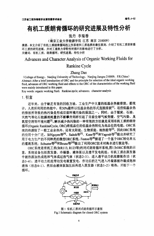
有机朗肯循环低品位热能发电系统,用低沸点 有机物代替常规朗肯循环中的水蒸气,使液态工质 在蒸发器中被低温热源加热为有机蒸气,进而推动 膨胀机做功,带动发电机发电,在膨胀机内做完功 的乏气进入冷凝器中再被冷却为液态,由工质泵升 压后打入蒸发器,从而完成整个动力循环。该系统
2
中国电机工程学报
第 33 卷
基金项目:河南省重点科技攻关计划项目(122102210041);河南省 教育厅科学技术研究重点项目(13A480722)。
The Key Scientific and Technological Planning Projects of Henan Province (122102210041); The Education Department of Henan Province Science and Technology Research Projects (13A480722).
窄点温差及工质物性对跨临界有机朗肯循环性能的影响
窄点温差及工质物性对跨临界有机朗肯循环性能的影响于超;徐进良;苗政;杨绪飞【摘要】利用约束热源入口及出口温度的热力学模型,将循环热效率及净输出功统一为一个参数,计算41种工质在473.15K 废热烟气驱动的跨临界有机朗肯循环中的热力学表现,分析蒸发器内窄点温差及工质物性对循环性能的影响。
结果表明,临界温度低于烟气出口温度的工质,及高于0.88倍烟气入口温度的工质,临界温度是循环效率的主要影响因素;临界温度在上述范围之间的工质,干湿性对循环效率影响显著,湿工质效率明显高于干工质。
所有循环中,该临界温度范围内的湿工质热效率最高。
临界温度高于0.88倍烟气入口温度的工质,窄点温差可能出现在蒸发过程中或蒸发器出口,从热力性能角度看,窄点出现在蒸发过程中的循环明显优于窄点出现在蒸发器出口的循环。
改变热源入口及出口温度不会影响上述结论。
%Thermal performance values of 41 working fluids in a trans-critical organic Rankine cycle (ORC) driven by waste heat flue gas of 473.15 K were calculated by means of a theoretical model in which the inlet and outlet temperatures of flue gas were fixed and therefore the thermal efficiency and net work output were unified into one parameter as long as the heat absorbed was given. The influences of pinch point temperature difference (PPTD) in the evaporator and working fluid properties on cycle performance were analyzed. Calculation results showed that for fluids with critical temperatureTc<Tgas,out, and fluids withTc>0.88Tgas,in,Tc had dominant influence on thermal efficiency. For fluids withTc betweenTgas,outand 0.88Tgas,in, fluid dryness had significant influence on cycle performance, and wet fluids outperformed dry fluids apparently. Wetfluids withTc between Tgas,outand 0.88Tgas,in exhibited the highest thermal efficiency. For fluids withTc>0.88Tgas,in, PPTD might lie either inside the evaporator or at the outlet. Thermal performance values of the cycle with PPTD inside the evaporator outperformed that with PPTD at the outlet. Application of such conclusions was confirmed through sensitivity analysis for flue gas inlet and outlet temperatures.【期刊名称】《化工学报》【年(卷),期】2014(000)012【总页数】9页(P4655-4663)【关键词】有机朗肯循环;跨临界循环;临界温度;窄点温差;热力学;热力学过程;热力学性质【作者】于超;徐进良;苗政;杨绪飞【作者单位】华北电力大学低品位能源多相流与传热北京市重点实验室,北京102206;华北电力大学低品位能源多相流与传热北京市重点实验室,北京 102206;华北电力大学低品位能源多相流与传热北京市重点实验室,北京 102206;华北电力大学低品位能源多相流与传热北京市重点实验室,北京 102206【正文语种】中文【中图分类】TK123Key words:organic Rankine cycle; trans-critical cycle; critical temperature; pinch point temperature; thermal dynamic; thermal process; thermal property工业低温余热烟气是重要的余热资源,对其进行回收可以获得经济效益及环保效益[1]。
混合工质有机朗肯循环
混合工质有机朗肯循环1. 引言混合工质有机朗肯循环是一种相对较新的热循环系统,它结合了混合工质和有机朗肯循环的优点,可以在多种能源转换场景下应用。
混合工质有机朗肯循环具有高效率、灵活性以及环境友好的特点,受到了广泛关注和研究。
本文将对混合工质有机朗肯循环的原理、应用以及未来发展进行全面、详细、完整地探讨。
2. 原理混合工质有机朗肯循环是一种以二氧化碳 (CO2) 和具有良好溶解性的气体混合物作为工质的热循环系统。
与传统的有机兰肯循环不同的是,混合工质有机朗肯循环采用了气液两相的工质,通过气相和液相的循环来完成能量转换。
混合工质有机朗肯循环的工质主要由两部分组成:CO2作为气相组分,具有较高的热稳定性和传热性能;具有良好溶解性的气体作为液相组分,能够提高工质的气液相变效率。
当工质通过热源接收热能时,气相中的CO2发生膨胀,产生功;当工质通过冷源释放热能时,CO2被液相吸收,实现能量回收。
3. 应用3.1 发电领域混合工质有机朗肯循环在发电领域具有广阔的应用前景。
与传统的蒸汽发电系统相比,混合工质有机朗肯循环可以在较低温度下实现高效发电,提高能源利用效率。
此外,混合工质有机朗肯循环还可以通过控制液相来调节系统的工作性能,具有良好的稳定性和灵活性,适用于多种发电模式。
3.2 能源转换领域混合工质有机朗肯循环的灵活性使其在能源转换领域具有广泛应用的潜力。
它可以与风能、太阳能等可再生能源结合,实现低温废热利用,提高能源转换效率。
此外,混合工质有机朗肯循环还可以与传统的燃煤、燃气等化石能源结合,减少排放物的产生,具有良好的环境效益。
3.3 工业领域混合工质有机朗肯循环在工业领域的应用也非常广泛。
它可以用于工业废热回收,提高能源利用效率;可以用于工业制冷和加热,实现能量的高效转换;可以用于工业过程的优化和节能减排。
混合工质有机朗肯循环在工业领域的应用将提高生产效率,降低能源成本,减少环境影响。
4. 未来发展混合工质有机朗肯循环作为一种新兴的能源转换技术,未来发展前景广阔。
- 1、下载文档前请自行甄别文档内容的完整性,平台不提供额外的编辑、内容补充、找答案等附加服务。
- 2、"仅部分预览"的文档,不可在线预览部分如存在完整性等问题,可反馈申请退款(可完整预览的文档不适用该条件!)。
- 3、如文档侵犯您的权益,请联系客服反馈,我们会尽快为您处理(人工客服工作时间:9:00-18:30)。
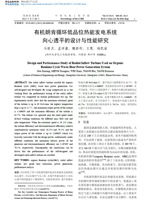
Transient operation of internal combustion engines with Rankine waste heat recovery systemsAlberto A.BorettiDepartment of Mechanical and Aerospace Engineering,Missouri University of Science and Technology,Rolla,MO,USAa r t i c l e i n f oArticle history:Received 11January 2012Accepted 18April 2012Available online 25April 2012Keywords:Rankine cyclesWaste heat recovery systems Internal combustion engines Light duty vehiclesa b s t r a c tPrior papers have shown the potentials of gasoline-like internal combustion engines fitted with Rankine cycle systems to deliver Diesel-like steady state fuel conversion ef ficiencies recovering the exhaust and the coolant waste heat with off-the-shelf components.In addition to the pros of the technology signi ficantly increasing steady state ef ficiencies e up to 5%in absolute values and much more in relative values e these papers also mentioned the cons of the technology,increased backpressures,increased weight,more complex packaging,more complex control,troublesome transient operation,and finally the cold start issues that prevent the uptake of the technology.This paper further explores the option to use Rankine cycle systems to improve the fuel economy of vehicles under normal driving conditions.A single Rankine cycle system is integrated here with the engine design.A latest turbocharged 1.6L direct injection engine has the coolant circuit modi fied to serve as pre-heater for the Rankine cycle fluid.This fluid is then vaporised and superheated in the boiler/superheater coaxial to the exhaust pipe located downstream of the turbocharger turbine and the closed coupled catalytic converter.The exhaust ports are insulated to reduce the heat losses.The pump of the Rankine cycle system is electrically operated.The expander of the Rankine cycle system drives a generator to recharge the traction battery pack.The thermal engine is connected to the transmission through an electric clutch and a motor/generator that permits to supplement/replace the thermal engine energy supply,recover the braking energy and start/stop the thermal engine.The integrated Rankine cycle system is intended to permit short warming-up pro files,reduced heat losses and reduced weight and packaging issues,delivering signi ficant bene fits during cold start driving cycles as the NEDC in addition to the long term,constant load and speed extra urban driving.Ó2012Elsevier Ltd.All rights reserved.1.Steady thermal engine results with organic Rankine cycle systemsPrior papers [1e 3]have shown the potentials of gasoline-like internal combustion engines fitted with organic Rankine cycle systems to deliver Diesel-like steady state fuel conversion ef fi-ciencies recovering the exhaust and the coolant waste heat with off-the-shelf components for what concerns heat exchangers,expanders and pumps.In addition to the pros of the technology signi ficantly increasing the steady state fuel conversion ef ficiencies e up to 5%in absolute values and much more than that in relative values,being zero the idle fuel conversion ef ficiency e these papers also mentioned the cons of the technology,increased back-pressures,increased weight,more complex packaging,more complex control,troublesome transient operation,and finally the cold start issues,that all prevent the uptake of the technology.The proposed engine has direct injection,turbo charging with a fixed geometry turbine,charge cooling and variable valve actu-ation.The main engine parameters are presented in Table 1.The engine has four valves per cylinder and a pent roof combustion chamber with central location of spark plug and direct injector.Fuel is directly injected within the cylinder and the engine is running stoichiometric to lower the emission of pollutants below Euro 4standards with a Three Way Catalytic (TWC)converter.The piston is modi fied to run ethanol with an increased compression ratio of 13:1as well as to better deal with the different fuels spray.The fuel injector is a fast,high pressure fuel injector for gasoline direct injection engines ideal for spray strati fied lean combustion appli-cations.The injection pressure from the fast actuating,multiple event high pressure injector is increased from 200to 300bar with ethanol.Injection is always performed after Intake Valve Closure (IVC).This has the advantage of injecting into hotter gas which helps to insure complete vaporization of the ethanol and prevents or minimizes wall wetting.The engine has the option to be controlled both by throttle and by reducing the intake valve lift.E-mail address:a_boretti@.Contents lists available at SciVerse ScienceDirectApplied Thermal Engineeringjournal ho mep age:www.elsevi/locate/apthermeng1359-4311/$e see front matter Ó2012Elsevier Ltd.All rights reserved.doi:10.1016/j.applthermaleng.2012.04.043Applied Thermal Engineering 48(2012)18e 23Differential reduction of the two valve lifts permit to control combustion modulating the tumble and swirl intensities.Ethanol has a Lower Heating Value (LHV)of 26.95MJ/kg,a stoichiometric air/fuel ratio of 9.00or a fuel-to-air ratio of 0.111,an amount of energy per kg of stoichiometric mixture of 2.695MJ/kg.Ethanol has a large Research Octane Number (RON),roughly 129.This permits higher compression ratios,higher boost in turbocharged engines,and better knocks limited spark advances.Ethanol also has a large heat of vaporization of 921kJ/kg.The amount of energy available per kg of stoichiometric mixture to cool the charge is 92.1kJ/kg.This allows better cooling of the in-cylinder charge in turbocharged DI engines.This latter feature further reduces the knock sensitivity.Density of ethanol is 794kg/m 3.Engine simulations have been performed using the WAVE code [4].The map of Fig.1is the basic engine maps to be modi fied recovering the exhaust heat and the coolant heat with a Rankine cycle system.The map presents the ratio of engine crankshaft power/fuel energy flow rate,basically the brake ef ficiency of the engine,and the brake-speci fic fuel consumption (BSFC),inversely proportional to the brake ef ficiency.The baseline ef ficiency with ethanol is higher than gasoline.This is mainly the result of a larger compression ratio,the use of a spark advance limited by knock closer to maximum brake torque and the use of a larger boost reducing the opening of the waste gate.Heat transfer is also reduced.Also worth of mention is the increased power and torque output vs.gasoline.The brake ef ficiency is the percentage of fuel energy transformed in usable work.A percentage of fuel energy is wasted in the exhaust gas heat.The exhaust temperature increases with the load and the speed,as it does the total mass flow rate.A percentage of fuel energy is also wasted in the coolant heat.The complement to 100%of the three contributions above is the other heat lost to the surrounding by radiation,convection and conduction.The WAVE model computes the amount of fuel energy converted into mechanical energy within the cylinder as well as the amount of fuel energywasted in the exhaust.The fuel energy wasted in the coolant heat must be guessed.For sake of simplicity,the other heat lost to the surrounding is taken a flat 10%of the fuel energy flow and the coolant heat flow is computed accordingly.Being the heat lost to the surrounding overestimated,the coolant heat flow rate is therefore underestimated.An R245fa organic Rankine cycle system assembled with off-the-shelf components (heat exchangers,expanders,pumps)[1e 3]was modelled by using GT-COOL [5].Different systems were used to recover the exhaust and the coolant heat.The system is made by a boiler e superheater,an expander,a recuperator,a condenser and a receiver pump.The R245fa moves from the boiler e superheater to the expander,then to the recuperator hot side,then to the condenser,then to the receiver pump and finally to the recuperator cold side.Pump ef ficiency close to 75%and expander ef ficiency close to 85%may be considered about design points.A flat 70%and 80%ef ficiency was used in the simulations.In addition to the condenser,receiver,pump,recuperator,expander,boiler/super-heater components,the model is made up of pipes and ori fices,two Proportional Integral Derivative (PID)controllers operating on the expander and the pump and exhaust and coolant in/out ambient.The fluid used was Genetron Ò245fa [6].In case of the organic Rankine cycle feed by the exhaust,the recovery ef ficiencies were around 14e 15%operating mid to high speeds and loads,while they deteriorated at low speeds and loads.The organic Rankine cycle on the exhaust has the problem of the backpressure.The recovery of energy in the organic Rankine cycle is made at the expenses of the increased backpressure that reduces the energy ef ficiency of the in-cylinder process.Turbocharged engines may better work with an increased backpressure than naturally aspirated engines.In case of the organic Rankine cycle feed by the engine coolant,the recovery ef ficiencies were around 5e 6%all over the range of speeds and loads.The organic Rankine cycle on the coolant has no downfall in terms of ef ficiency.The amount of energy recovered is not great,but there are no embedded ef ficiency penalty issues to consider.Fig.2presents the augmented brake ef ficiency (brake power þexpander Àpump power)/fuel energy flow rate that the ethanol engine would have recovering the exhaust and coolant heat with an organic Rankine cycle.The organic Rankine cycle system fitted on the exhaust is effective particularly at high speeds and loads.The organic Rankine cycle system fitted on the coolant is effective particularly at low speeds and loads.The numbers obtained using the two combined organic Rankine cycle systems certainly need further investigations,but are certainly reasonable targets.A hybrid thermal e electric power train con figuration is neces-sary to ef ficiently operate organic Rankine cycle pump and expander and deliver part of the recovered energy to the trans-mission.A sketch of the minimum components for this hybrid power train is presented in Fig.3.The thermal engine is connected to the transmission through an electric clutch and a motor/Table 1Engine parameters.Bore B (mm)80Stroke S (mm)80Bore to stroke ratio B/S1Connecting rod length (mm)135Compression ratio CR13:1Injection rail pressure (bar)200Intake valve reference diameter D i (mm)27Exhaust valve reference diameter D e (mm)24Intake valve maximum lift h i (mm)8.5Exhaust valve maximum lift h e (mm)8.5Intake Valve Opening IVO (deg.crank angle)350 (10 BTDC)Intake Valve Closure IVC (deg.crank angle)580 (40 ABDC)Exhaust Valve Opening EVO (deg.crank angle)140 (40 BBDC)Exhaust Valve Closure EVC (deg.crank angle)370(10ATDC)Fig.1.Engine crankshaft power/fuel energy flow rate (left)and brake-speci fic fuel consumption (right)of the ethanol engine without organic Rankine cycle systems.A.A.Boretti /Applied Thermal Engineering 48(2012)18e 2319generator that permits to supplement the thermal engine energy supply,to recover the braking energy and to start/stop the thermal engine.The waste heat recovery system has a component deliv-ering energy to the traction battery e the expander e and using energy from the traction battery e the pump.Almost all the latest hybrid thermal e electric vehicles may accept the waste heat recovery system proposed here with only minor changes.The Toyota Prius [10]or the Honda Insight or Civic [11]would certainly be perfect candidates to implement this waste heat recovery technology.Some factors reduce these figures.Electric hybrid power trains permit an easier recovery of the expander power through a gener-ator charging the traction battery.However,penalties in ef ficiency apply transforming the mechanical energy in chemical energy and then back to mechanical energy.The organic Rankine cycle system downstream of the catalytic converter has no impact on the after treatment,but still has a negative effect on backpressure that may reduce the ef ficiency of the in-cylinder energy transfer.The coolant circuit will have an increased backpressure and the coolant pump will then absorb more power reducing the power at the crankshaft.Heat losses will finally occur.Fig.4presents the power at the transmission/fuel energy flow rate and the equivalent thermalengine brake-speci fic fuel consumption map assuming 70%of the energy at the expander shaft is transferred to the transmission.2.Vehicle fuel consumption simulations with a novel Rankine cycle systemA novel Rankine cycle system has been conceived evolving the BMW Turbo steamer concept [8,9].In the Turbo steamer,a liquid is heated to form steam in two circuits.The primary energy supplier is the high temperature circuit which uses exhaust heat from the internal combustion engine as an energy source via heat exchangers.The steam is then conducted directly into an expansion unit linked to the crankshaft of the internal combustion engine.Most of the remaining residual heat is absorbed by the cooling circuit of the engine,which acts as the second energy supply for the Turbo steamer.The Turbo steamer is made up by three circuits.The water-cooling circuit receives heat from the engine passages and gives heat to the steam generator of the low temperature circuit.The high temperature circuit receives heat from the exhaust gases and gives heat to the low temperature circuit.The low temperature circuit receives heat from the water-cooling and the high temper-ature circuits as well as from the exhaust gases and gives heat to the radiator.All the three circuits have fluid circulation forced by pumps while the low and high temperature circuits feed two expanders connected to the crankshaft.The proposed novel Rankine cycle system is made simpler by using two or even only one circuit rather than three.Both solutions are currently under evaluation,with the latter being the most promising.The two circuits design is made up of the water-cooling circuit and the Rankine cycle circuit.The water-cooling circuit receives heat from the engine passages and gives heat to the boiler/pre-heater of the Rankine circuit.The Rankine cycle circuit is made up of the boiler/pre-heater,a boiler/superheater (a heat exchanger immediately downstream of the catalytic converter),an expander,a recuperator,a condenser (the radiator)and a pump.The single circuit design removes the water-cooling circuit and uses the engine coolant passages as the boiler/pre-heater above.The Rankine cycle working fluid moves from the boiler/pre-heater to the recuperator cold side to the boiler/superheater to the expander,then to the recuperator hot side,then to the condenser,and then to the pump.The working fluid,which is repeatedly vaporized,expanded,and re-condensed,plays a key role in the capability and cost-effectiveness of a Rankine steam cycle heat recovery system.To optimize the work output for a given temperature gradient,the evaporation enthalpy of the working fluid should be as high as possible.Water has the higher evaporation enthalpy (2250kJ/kg),followed by alcohols (methanol 1100kJ/kg,ethanol 820kJ/kg).The working fluid considered so far has been water for the single circuit design and ethanol for the two circuits design.The pump of the Rankine cycle system is electrically operated and the expander of the Rankine cycle system drives a generator to recharge the traction battery pack.The pump of the water-cooling circuit (when present)is also electrical.A sketch of the single circuit design is shown in Fig.5.The minimal option includes the boiler e pre-heater and the boiler e superheater one after the other,then the expander,the condenser and the pump.The water enters the engine coolant passages and exits with higher temperature.Partial vaporisation may be considered within the coolant passages if care is taken to account for the different heat transfer properties of water and water/steam mixtures in the design of the cylinder head.Then,the water/steam enters the coaxial counter flow heat exchangers on the exhaust system to fully vaporise.The steam then expands in the expander that recharges the traction battery.Afterexpansion,Fig.2.Engine crankshaft þexpander shaft Àpump shaft power/fuel energy flow rate of the 1.6ethanol engine with organic Rankine cyclesystems.Fig.3.Sketch of the mild hybrid power train con figuration.A.A.Boretti /Applied Thermal Engineering 48(2012)18e 2320the steam is then condensed in the radiator and the water is sent back to the engine coolant passages by a pump feed by the traction battery.Expander and pump are independently operated.A by-pass is needed to change the mass flow rate through the waste heat recovery system components.The Rankine cycle considered is enhanced vs.the basic cycle through superheating.Diagrams for a Rankine cycle with super-heating are given in Fig.6.The heat addition is continued past the point of vapour saturation,in other words the vapour is heated so that its temperature is higher than the saturation temperature associated with P a ^P b ¼P c ¼P d .This increases the mean temperature at which heat is added thus increasing the ef ficiency of the cycle.The quality of the two-phase mixture during the expansion is also higher with superheating,so that there is less moisture content in the mixture as it flows through the expander.Superheating increases the turbine work,increases the mean temperature at which heat is received,and increases the cycle ef fi-ciency compared to the basic cycle.This integrated Rankine cycle system is supposed to deliver same bene fits of those previously computed and presented in Fig.4.In addition,this system permits short warming-up pro files,reduced heat losses and reduced weight and packaging issues,therefore delivering signi ficant fuel economy bene fits during cold start driving cycles as the New European Driving Cycle (NEDC)in addition to the bene fits over the constant load and speed extra urban driving.Fuel economy is measured over test cycles.TheFig.4.Power at the transmission/fuel energy flow rate and equivalent engine brake-speci fic fuel consumption of the 1.6ethanol engine with organic Rankine cyclesystems.Fig.5.Sketch of the novel Rankine cycle system with (left)and without (right)a recuperator.The boiler/pre-heather is the cylinder head water passages;the boiler/superheater is a heat exchanger on the exhaust immediately after the closed coupled catalyticconverter.Fig.6.Rankine cycle with superheating in P e v (left),T e s (centre)and h e s (right).A.A.Boretti /Applied Thermal Engineering 48(2012)18e 2321ECE þEUDC cycle is a test cycle performed on a chassis dyna-mometer used for emission certi fication of light duty vehicles in Europe [EEC Directive 90/C81/01].The entire cycle includes four ECE segments,repeated without interruption,followed by one EUDC segment.Before the test,the vehicle is allowed to soak for at least 6h at a test temperature of 20e 30 C.It is then started and the emission sampling begins at the same time.This cold start proce-dure is also referred to as the New European Driving Cycle (NEDC).The ECE cycle is an urban driving cycle,also known as UDC.It was devised to represent city driving conditions,e.g.in Paris or Rome.It is characterized by low vehicle speed,low engine load,and low exhaust gas temperature.The EUDC (Extra Urban Driving Cycle)segment has been added after the fourth ECE cycle to account for more aggressive,high speed driving modes.The maximum speed of the EUDC cycle is 120km/h Table 2summarizes the parameters for both the ECE and EUDC cycles.NEDC simulations have then been performed for a large full size passenger car with the Lotus Vehicle Simulation (LVS)software [7].The main vehicle parameters are summarized in Table 3.Simulations are performed for the turbo-charged ethanol engine following various hypotheses.The trans-mission and final drive ratios have been de fined for the baseline 4L naturally aspirated gasoline engine and not for the novel 1.6L turbocharged ethanol engine.The vehicle mass is not changed to account for the change of the engine.Fig.7presents the experimentally measured fuel flow rate and temperatures of engine media (coolant,oil)for the vehicle equip-ped with the 4L gasoline engine.The throttle opening at idle is larger during the cold start,as well as the idle speed of the engine.The fuel-to-air ratio is close to the stoichiometric value.More fuel is used during the first ECE segment at idle.After the first ECE segment,the fuel consumption penalty due to the cold start strategy drastically reduces and becomes almost negligible.The first ECE segment requires 148.9g of gasoline fuel,the second ECE segments 103.9g,the third ECE segment 96.5g and the fourth ECE segment 89.6g.The EUDC segment requires 406.0g for a total fuel consumption of 845.0g of gasoline fuel.This translates in 77.5g/km or 10.3L/100km.While considering only the four ECE segments,the cold start fuel economy penalty is roughly 22.5%,while considering all the NEDC the cold start fuel economy penalty is roughly 10.5%.The coolant temperature is actually the cylinder head metal temperature in a location very close to the water jacket.The oil never reaches the fully warmed-up temperatures,while the coolant reaches the fully warmed-up temperature after 800s.Fig.8presents the target temperatures of oil and coolant for the 1.6ethanol engine and the fuel flow rate computed using the warmed-up engine map of Fig.1and an empirical cold start fuel penalty.The coolant reaches the fully warmed-up values in 600s,and the oil reach the fully warmed-up values in 1000s.This assumption is quite conservative,because the small high power density engine will deliver a much faster warm-up than the large low power density engine even without any design change to produce a faster warm-up.This baseline con figuration uses 959.0g of ethanol fuel to cover the NEDC.Worth of mention is that the integrated Rankine cycle system also permits a faster warm-up of the engine thanks to the optimal operation of the water electrically operated pump and also using the exhaust gas heat for the purpose.This opportunity is not considered here.With the Rankine cycle system fitted,a weight of 50kg is added to simulate the extra mass of the Rankine cycle system.These 50kg are a very pessimistic assumption especially for the novel single cycle turbosteamer.The Rankine cycle system may provide an even faster warm-up by using part of the exhaust heat to heat the engine.Therefore,it is a conservative assumption to assume that the engine warms up in the same 600s with the Rankine cycle system fitted.We assume that the Rankine cycle system is not effective up to 600s and fully operational after that time.If the warmed-up BSFC map of Fig.1is used up to 600s and the warmed-up BSFC map of Fig.3becomes effective after 600s,then the fuel consumption with the extra weight is 918.5g for an improvement of the fuel economy of 4.2%over the cold start NEDC.Obviously,with a faster warm-up and with a reduced weight penalty,the fuel economy bene fits are expected to further increase.Also worth of mention is that cruising at 120km/h with the engine warmed-up,the 1.6L ethanol engine with Rankine cycleTable 2Main characteristics of ECE and EUDC cycles.CharacteristicsECE 15EUDC Distance [km]4Â1.013¼4.052 6.955Duration [s]4Â195¼780400Average speed [km/h]18.7(with idling)62.6Maximum speed [km/h]50120Table 3Vehicle parameters.Mass m [kg]1810Frontal area A [m 2] 2.250Drag coef ficient C D0.298Rolling tore radius r [m]0.3160Transmission5-speed automaticTransmission ratios 3.22/2.29/1.55/1.00/0.75Final drive ratio2.730Fig.7.Measured engine fuel flow rate and temperatures of oil and coolant (cylinder head metal)for the 4L gasoline engine.A.A.Boretti /Applied Thermal Engineering 48(2012)18e 2322system and a weight penalty of 50kg requires a fuel flow rate of 2.80g/s vs.the 3.00g/s of the engine without Rankine cycle system and no weight penalty for a fuel economy 6.7%better.The proposed hybrid con figuration also permits the recovery of the braking energy,the start/stop of the thermal engine and the optimum mix of thermal and electric motor power supply in all the possible driving conditions to deliver much better fuel economies.3.ConclusionsThis work has shown the opportunity to recover the exhaust and the coolant waste heat in a hybrid passenger car covering a cold start driving cycle.The integrated Rankine cycle system permits a 4.2%better fuel economy over the full NEDC and a 6.4%better fuel economy when cruising at 120km/h with the engine fully warmed-up.The integrated Rankine cycle system also permits a faster warm-up of the engine thanks to the optimal operation of the water electrically operated pump and also using the exhaust gas heat for the purpose.This produces further improvements of the fuel economy reducing the cold start penalty not considered here.Other improvements of the vehicle fuel economy are permitted by the hybrid power train as presently neglected to focus on the waste heat recovery issues.The hybrid power train permits the recovery of the braking energy,the start/stop of the thermal engine and the optimum mix of thermal and electric motor power supply for much better fuel economies over driving cycles.The optimal recovery of the waste heat from the exhaust and coolant requires a proper redesign of the power unit,being the boiler/pre-heater the coolant passages and the boiler/superheater a gas exchanger close to the cylinder head for the best performances.References[1] A.Boretti,Stoichiometric H2ICE with water injection and exhaust and coolantheat recovery through organic Rankine cycles,International Journal of Hydrogen Energy 36(19)(2011)12591e 12600.[2] A.Boretti,Recovery of exhaust and coolant heat with R245fa organic Rankinecycles in a hybrid passenger car with a gasoline engine,Applied Thermal Engineering 36(April 2012)73e 77.[3] A.Boretti,Energy recovery in passenger cars,Journal of Energy ResourcesTechnology 134(2)(June 2012)022203.[4]Ricardo,“Wave ”/What-we-do/Software/Products/WAVE/(retrieved January 10,2012).[5]Gamma technologies,“Gt-Cool ”/img/broch/broch_gtcool.pdf (retrieved January 10,2012).[6]Honeywell,“Genetron Ò245fa ”/sm/chemicals/refrigerants/eu/en/products-n2/organic-n3/organic-genetron 245fa.html?c ¼25(retrieved January 10,2012).[7]Lotus Engineering Software,“Lotus Vehicle Simulation (LVS)”.www.lotuscars.com/engineering/en/lesoft-products (retrieved January 10,2012).[8]J.Ringler,M.Seifert,V.Guyotot,W.Hübner,“Rankine Cycle for Waste HeatRecovery of IC Engines ”,SAE 2009-01-0174.[9] ,“BMW Unveils the Turbo Steamer Concept ”,www./index.php/articles-and-reviews-mainmenu-3/bmw-innovations/65-169(retrieved January 10,2012).[10]Toyota,“How Hybrids Work ”..au/hybrid-synergy-drive/hybrid-technology/how-hybrid-works (retrieved January 10,2012).[11]Honda,“Hybrid ”./Hybrid/(retrieved January 10,2012).puted fuel flow rate and temperatures of oil and coolant for the 1.6L ethanol engine without Rankine cycle system (warmed-up engine BSFC map of Fig.1and empirical cold start fuel penalty).A.A.Boretti /Applied Thermal Engineering 48(2012)18e 2323。