rfc4224.RObust Header Compression (ROHC) ROHC over Channels That Can Reorder Packets
艾泰4220G 与ROS 建立IPSec 连接。

艾泰4220G 与ROS 建立IPSec 连接。
IPSec 方式的VPN相信是大部分企业建立与各分公司之间的联系通道的首选方式之一,它方便、安全、可兼容性高,等等……
优点不必多说。
下面就我公司刚刚换用的艾泰4220G 与两个分厂区之间的IPSec 建立为例说一下艾泰与最流行的软路由ROS的互联方法。
注:总部和两个分厂均为10M光纤接入,都使用固定IP地址。
总部网络参数
公网IP: 218.85.157.99 (此处为假设,具体看各自的网络状态。
这个其实是福建省电信的DNS服务器IP。
)
内网: 192.168.10.1 255.255.255.0
分厂区一:218.85.152.99 (嘿嘿,此处同样是福建电信的一台DNS服务器)
内网:192.168.20.1 255.255.254.0
分厂区二: 218.85.150.99 (这个随便写的,我也不知道是哪的IP)
内网:192.168.2.1 255.255.255.0
首先,是艾泰的设置:
接下来是ROS的设置:
登陆 WINBOX 进入 IP——>IPSec
1.先设置好默认的ipsec验证方式,总共有两次验证,这里大概是第一次吧。
2.设置peer
3。
做路由规则
访问 IP——>Firewall 进入NAT标签页。
新建一条规则:
另外,记得在 Action 标签页中选择 accept OK,这样,艾泰和ROS之间的IPSec连接完成了。
最后放上连接成功的状态照:。
ROHC

x Instead, use SN as “kernel field”
– Send it with every packet – Losses or pre-compressor reorderings are apparent!
x VJ HC has been available for a long time x CRTP implementations now in the leading products x PPP/IP/UDP/RTP now qualifies as an efficient method to run multimedia information over serial lines
RTP sequence number
UDP
RTP timestamp synchronization source (SSRC) identifier contributing source (CSRC) identifiers
2001 Carsten Bormann
RTP
TZI Digitale Medien und Netze
Robust Header Compression (ROHC)
A steps networks
Carsten Bormann TZI
2001 Carsten Bormann
TZI Digitale Medien und Netze
ISSLOW: Integrated Services over slow links Background: RTP is replacing TDM
– no need for TDM style multiplexes any more – no problems with integration of data and multimedia
施耐德电气低压配电产品选型指南说明书
ABB EntrelecSommaireBU0402061SNC 160 003 C0205SummarySelection guide ....................................................................................page 1Screw clamp ........................................................................................page 2Feed through and ground terminal blocks .......................................................page 2 - 5 to 10Single pole, multiclamp terminal blocks..........................................................................page 4Feed through terminal blocks - Double-deck................................................................page 11Feed through terminal blocks - Triple-deck...................................................................page 12Three level sensor, terminal blocks without ground connection...................................page 13Three level sensor, terminal blocks with ground connection ........................................page 14Terminal blocks for distribution boxes, double deck + protection .......................page 15 - 16Interruptible terminal blocks for neutral circuit......................................................page 17 - 18Distribution : phase, ground terminal blocks .......................................................page 19 to 21Single pole or four pole distribution blocks..........................................................page 22 to 24Heavy duty switch terminal blocks with blade......................................................page 25 - 26Heavy duty switch terminal blocks with push-turn knob..............................................page 26Heavy duty switch terminal blocks with contact control pull lever...............................page 29Heavy duty switch terminal blocks with blade - Double-deck .....................................page 27Fuse holder terminal blocks for 5x20 mm (.197x.787 in.) and 5x25 mm (.197x.984 in.)or 6.35x25.4 mm (1/4x1 in.) and 6.35x32 mm (1/4x11/4 in.) fuse s.........................................page 28 - 29Fuse holder terminal blocks for 5x20 mm (.197x.787 in.) and 5x25 mm (.197x.984 in.) fuses -Double-dec k.....................................................................................................................page 27Terminal blocks for test circuits with sliding bridge ......................................................page 30Terminal blocks for metering circuits.............................................................................page 31ESSAILEC terminal blocks.............................................................................................page 32Safety connection terminal blocks ................................................................................page 33Miniblocks for EN 50045 (DIN 46277/2) rail ..........................................................page 34 - 35Spring clamp ......................................................................................page 36Angled terminal blocks - Feed through and ground .....................................................page 36Feed through and ground terminal blocks ...........................................................page 37 to 41Feed through terminal blocks - Double deck ................................................................page 42Terminal blocks for sensors / actuators ........................................................................page 42Terminal blocks for distribution boxes...........................................................................page 43Switch terminal blocks for neutral conductor........................................................page 44 - 45Heavy duty switch terminal blocks with blade..............................................................page 46Fuse holder terminal blocks for 5x20 mm (.197x.787 in.) and 5x25 mm (.197x.984 in.) fuse s....page 47Miniblocks Spring clamp ......................................................................................page 48 to 52ADO - Screw clamp ...........................................................................page 53Feed through and ground terminal blocks ...........................................................page 53 to 56Feed through and ground terminal blocks - Double-deck............................................page 57Heavy duty switch terminal blocks with blade..............................................................page 58Fuse holder terminal blocks for 5x20 mm (.197x.787 in.) and 5x25 mm (.197x.984 in.) fuse s ......page 59 - 60Miniblocks ADO - Screw clamp............................................................................page 61 to 65ADO - ADO .........................................................................................page 66Feed through and ground terminal blocks ...........................................................page 66 to 69Feed through and ground terminal blocks - Double-deck............................................page 70Terminal blocks for sensors / actuators ........................................................................page 71Heavy duty switch terminal blocks with blade..............................................................page 72Fuse holder terminal blocks for 5x20 mm (.197x.787 in.) and 5x25 mm (.197x.984 in.) fuse s ......page 73 - 74Miniblocks ADO - ADO .........................................................................................page 75 to 79Accessories ADO ...........................................................................................................page 80Power terminal blocks .............................................................page 81 to 84Quick-connect terminal blocks .................................................page 85 - 86Terminal blocks for railway applications ................................page 87 to 97Pluggable terminal blocks .....................................................page 98 to 100Accessories......................................................................................page 101Marking..................................................................................page 102 to 104GrossAutomation(877)268-3700··*************************PR30PR3.Z2PR3.G2PR5PR4PR1.Z2Rated wire size :Rated wire size :Rated wire size :Rated wire size :Mounting railsShield terminals forcollector barMarking tableHorizontal Rated wire size :0.5 to 16 mm² (22 to 8 AWG)Rated wire size :Rated wire size :Rated wire size :P a g e t o 29e30 t o 32ag e e3P a ge 8 t o 60a g e6t o 6574P a ge 7 t o 79P a ge 9P a g P a gGrossAutomation(877)268-3700··*************************2ABB Entrelecd010830402051SNC 160 003 C0205MA 2,5/5 - 2.5 mm² blocks - 5 mm .200" spacingAccessoriesGrossAutomation(877)268-3700··*************************3ABB Entrelec D010740402051SNC 160 003 C0205M 4/6 - 4 mm² blocks - 6 mm .238" spacingAccessoriesGrossAutomation(877)268-3700··*************************4ABB EntrelecD011030402051SNC 160 003 C0205M 4/6.3A - 4 mm² blocks - 6 mm .238" spacingM 4/6.4A - 4 mm² blocks - 6 mm .238" spacingGrossAutomation(877)268-3700··*************************5ABB Entrelec D010840402051SNC 160 003 C0205M 6/8 - 6 mm² blocks - 8 mm .315" spacingAccessoriesGrossAutomation(877)268-3700··*************************6ABB EntrelecD010850402051SNC 160 003 C0205M 10/10 - 10 mm² blocks - 10 mm .394" spacingAccessoriesGrossAutomation(877)268-3700··*************************7ABB Entrelec D010860402051SNC 160 003 C0205M 16/12 - 16 mm² blocks - 12 mm .473" spacingAccessoriesGrossAutomation(877)268-3700··*************************8ABB EntrelecD010870402051SNC 160 003 C0205M 35/16 - 35 mm² blocks - 16 mm .630" spacingGrossAutomation(877)268-3700··*************************M 95/26 - 95 mm² blocks - 26 mm 1.02" spacingM 70/22.P - 70 mm² ground block with rail contact - 22 mm .630" spacingSelection35 mm / 1.37"12 mm / 0.47"14-30 Nm / 124-260 Ib.in 1.2-1.4 Nm / 10.6-12.3 Ib.in1000600600415400400577070240 mm 2500 MCM 500 MCM 10 mm 2 6 AWG 6 AWG IEC UL CSANFC DIN0.5 - 160.5 - 100 AWG-600 MCM 2 AWG-500 MCM 50 - 30035 - 24018-6 AWGD 150/31.D10 - 150 mm² blocks - 31 mm 1.22" spacingCharacteristicsD 240/36.D10 - 240 mm² blocks - 36 mm 1.41" spacingSelectionWire size main circuit mm² / AWG VoltageV Current main circuit A Current outputARated wire size main circuit mm² / AWG Rated wire size outputmm² / AWG Wire stripping length main circuit mm / inches Wire stripping length output mm / inches Recommended torque main circuit Nm / Ib.in Recommended torque outputNm / Ib.inSolid Stranded Solid Stranded Wire size output mm² / AWG9.5 mm / .37"0.5-0.8 Nm / 4.4-7.1 Ib.in5003003003220204 mm 212 AWG12 AWG0.2 - 422-12 AWG 22-12 AWG 0.22 - 4IEC ULCSANFC DINCharacteristicsWire size mm² / AWGSolid Stranded D 4/6.T3 - 4 mm² blocks - 6 mm .238" spacingSelectionVoltage V CurrentARated wire sizemm² / AWG Wire stripping length mm / inches Recommended torqueNm / Ib.inM 4/6.T3.P - 4 mm² block - 6 mm .238" spacingD 2,5/6.D - 2.5 mm² blocks - 6 mm .238" spacingD 2,5/6.DL - 2.5 mm² blocks - 6 mm .238" spacingD 2,5/6.DPA1 - 2.5 mm² blocks - 6 mm .238" spacingD 2,5/6.DPAL1 - 2.5 mm² blocks - 6 mm .238" spacingD 4/6... - 4 mm² blocks - 6 mm .238" spacingD 4/6.LNTP - 4 mm² closed blocks - 17.8 mm .700" spacingMA 2,5/5.NT- 2.5 mm² block - 5 mm .200" spacingAccessories**SFB2 : 16 to 35 mm² 6 to 2 AWG H= 3 mm/.12"M 10/10.NT- 10 mm² block - 10 mm .394" spacingAccessories(1) Except for M 35/16 NT (closed block)*SFB1 : 0.5 to 35 mm² 18 to 2 AWG H= 7 mm/.28"**SFB2 : 16 to 35 mm² 6 to 2 AWG H= 3 mm/.12"MB 4/6... - 4 mm² blocks - 6 mm .238" spacingMB 6/8... - 6 mm² blocks - 8 mm .315" spacingMB 10/10... - 10 mm² blocks - 10 mm .394" spacingBRU 125 A - 35 mm² block - 27 mm 1.063" spacingBRU 160 A - 70 mm² block - 35.2 mm 1.388" spacingBRU 250 A - 120 mm² blocks - 44.5 mm 1.752" spacingBRU 400 A - 185 mm² block - 44.5 mm 1.752" spacingAccessoriesAccessoriesBRT 80 A - 16 mm² block - 48 mm 1.89" spacingBRT 125 A - 35 mm² block - 48 mm 1.89" spacingBRT 160 A - 50 mm² block - 50 mm 1.97" spacing9.5 mm / .37"0.5-0.6 Nm / 4.4-5.3 Ib.in4003003002010104 mm 210 AWG 12 AWG 0.5 - 422-10 AWG20-12 AWG0.5 - 2.5IEC ULCSANFC DINMA 2,5/5.SNB - 2.5 mm² blocks - 5 mm .200" spacingCharacteristicsM 4/6.SNB - 4 mm² blocks - 6 mm .238" spacingSelectionWire size mm² / AWGVoltage V CurrentARated wire sizemm² / AWG Wire stripping length mm / inches Recommended torqueNm / Ib.inSolid StrandedM 6/8.SNB - 6 mm² blocks - 8 mm .315" spacing - blade switchingSelectionAccessoriesM 4/8.D2.SF - for fuses 5x20 mm .197x.787 in. and 5x25 mm .197x.984 in. -4 mm² blocks - 8 mm .315" spacingM 4/6.D2.SNBT - 4 mm² blocks - 6 mm .238" spacing - blade switchM 4/8.SF- 4 mm² blocks - 8 mm .315" spacingM 4/8.SFL - 4 mm² blocks - 8 mm .315" spacing12 mm / .472"1.2-1.4 Nm / 10.6-12.3 Ib.in800(1)60060016252510 mm 210 AWG8 AWG0.5 - 1622-10 AWG 22-8 AWG 0.5 - 10IEC ULCSANFC DINCBD2SML 10/13.SF - for fuses 6.35x25.4 mm 1/4x1 in. and 6.35x32 mm 1/4x11/4 in. -10 mm² blocks - 13 mm .512" spacingSelectionAccessoriesCharacteristicsWire size mm² / AWGVoltage V CurrentARated wire sizemm² / AWG Wire stripping length mm / inches Recommended torqueNm / Ib.inSolid Stranded (1) Insulation voltage of terminal block - operating voltage : according to fuse.M 4/6.D2.2S2... - 4 mm² blocks - 6 mm .238" spacing11 mm / .43"0.8-1 Nm / 7.1-8.9 Ib.in50060030306 mm 28 AWG0.5 - 1022-8 AWG0.5 - 6IECULCSANFC DINM 6/8.ST... - 6 mm² blocks - 8 mm .315" spacingCharacteristicsWire size mm² / AWGVoltage V CurrentARated wire sizemm² / AWG Wire stripping length mm / inches Recommended torqueNm / Ib.inSolid Stranded M 6/8.STA - 6 mm² blocks - 8 mm .315" spacing(3)Only for M 6/8.STAM 4/6.ST- 4 mm² blocks - 6 mm .236" spacingBNT...PC...(2) Only for M10/10.ST-SnThe PREM IUM solution for testing the secondary circuits of current or voltage transformers.ESSAILEC, approved by the major electricity utilities, remains the premium choice for the energy market.Implemented in the transformers secondary circuits, ESSAILEC thanks to its intelligent “make before break” design eases and secures any intervention. Cutting the energy supply is avoided with zero risk for the operator.The plug and socket connection cuts cost installation as well as in-situ wiring errors. ESSAILEC is ideal for the wiring of sub-assemblies in the secondary circuits.ESSAILEC terminal blocksProtection relays,Protection relays,Testing :The ESSAILEC socket supplies energy to the protection or counting devices. The insertion of the test plug, which is connected to the measurement equipment, allows the testing of the devices, without perturbing the circuit.ESSAILEC blocks are well adapted to current or voltage measurement :-Current sockets with make before break contacts and pre-wired test plug for current measures-Voltage sockets with open contacts and pre-wired test plug for voltage measures-Up to 4 ammeters or 4 voltmeters connected to the test plugDistributing :The ESSAILEC plug is continuously mounted on the socket to supply current or voltage to secondary circuits sub assemblies.ESSAILEC blocks extreme versatility allow :-Safe current distribution with current socket with mobile contacts since the secondary circuit is not cut when plug is removed-Voltage or polarity distribution with dedicated voltage or polarity socket with closed contactESSAILEC is designed to offer :Great flexibility :-Connection multi contacts « plug and play »-Panel, rail, rack fixed mounting or stand-alone connector -Two wiring technologies, up to 10 mm²Extreme reliability :-Non symmetric blocks -Coding accessories -IP20 design -Locking system -Sealed coverR S T NFor technical characteristics and complete part numbers list, please ask for the ESSAILEC catalog10005006003225254 mm 21.65 mm²12 AWG 13 mm / .51"IECB.SCSANFC DINTS 50-180.5 - 0.8 Nm /4.4 - 7.1 Ib.in0.2 - 422-12 AWG0.22 - 40.5 - 1.50.28 - 1.6580050060041252562.512 AWG 13 mm / .51"0.8 - 1 Nm / 7.1 - 8.9 Ib.inIECB.S CSANFC DINTS 50-180.5 - 1020-12 AWG0.5 - 60.28 - 2.590050060046406510 mm 26 mm² 6 AWG 14 mm / .55"IECB.S UL/CSANFC DINTS 50-181.2 - 1.4 Nm / 10.6 - 12.3 Ib.in0.5 - 1620 - 6 AWG0.5 - 100.28 - 6M 4/6.RS - 4 mm² blocks - 6 mm .238" spacingCharacteristicsWire size mm² / AWGVoltage V CurrentARated wire sizemm² / AWG Wire stripping lengthmm / inches Recommended torque (screw)Nm / Ib.inSolid wire Stranded wire Solid wire Stranded wire Screw clampLugsM 6/8.RS - 6 mm² blocks - 8 mm .315" spacingCharacteristicsWire size mm² / AWGVoltage V CurrentARated wire sizemm² / AWG Wire stripping lengthmm / inches Recommended torque (screw)Nm / Ib.inSolid wire Stranded wire Solid wire Stranded wire Screw clampLugspending M 10/10.RS - 10 mm² blocks - 10 mm .394" spacingCharacteristicsWire size mm² / AWGVoltage V CurrentARated wire sizemm² / AWG Wire stripping lengthmm / inches Recommended torque (screw)Nm / Ib.inSolid wire Stranded wire Solid wire Stranded wire Screw clampLugspending SelectionAccessories(1) Only for block M 4/6.RS (4) For blocks M 4/6.RS and M 6/8.RS(2) Only for block M 6/8.RS(3) Only for block M 10/10.RSDR 1,5/4 - 1.5 mm² blocks - 4 mm .157" spacingDR 1,5/5... - 1.5 mm² blocks - 5 mm .200" spacing。
EXFO 2000 系列以太网测试仪 中文说明书

S P E C S H E ETKEY FEATURES AND BENEFITSAccelerate Ethernet service activation with bidirectional EtherSAM (Y .156) and RFC 2544 test suites, multistream traffi c generation, Through mode and bit-error-rate (BER) testing Experience unprecedented confi guration simplicity with hybrid touchscreen/keypad navigation and data entry Increase technician autonomy and productivity with intelligent discovery of remote EXFO Ethernet testers, as well as in-service testing via dual-port Through mode Eliminate errors in data interpretation with revolutionary new GUI on 7-inch TFT screen, historical event logger, visual gauges and 3D-icon depictions of pass/fail outcomesSimplify reporting with integrated Wi-Fi and Bluetooth connectivity capabilitiesIntegrated applications to test VoIP services, and additional IP test utilities including VLAN scan and LAN discovery via EXpert VoIP and EXpert IP test toolsSupport for packet capture and analysis, wireless troubleshooting and TCP throughput testingExtend fi eld testing operations with compact, lightweight platform equipped with long-duration battery packFTB-860 NetBlazer Series Ethernet TestersPOWERFUL, FAST, INTUITIVE ETHERNET TESTINGeld technicians comprehensive, yet simple test suites to quickly and easily turn up, validate and troubleshoot Ethernet services, with full EtherSAM capabilities, from 10 Mbit/s to 10 Gbit/s.EXFO FTB-1 FTB-860G SpecsProvided by THE ULTRA-PORTABLE CHOICE FOR HIGH-SPEED ETHERNET TESTINGThe ongoing deployment of GigE and 10 GigE circuits across access and metro networks demands a testing solution that seamlessly adapts to either operating environment—without sacrificing portability, speed or cost—in order to guarantee the performance and quality of service (QoS) metrics of these services.Leveraging the powerful, intelligent FTB-1 handheld platform, the NetBlazer series streamlines processes and empowers field technicians to seamlessly transition between 10/100/1000/10000 interfaces to rapidly adapt to a variety of networking environments.Powerful and FastThe NetBlazer series is a portfolio of fully integrated 10 Mbit/s to 10 Gbit/s handheld Ethernet testers. Available in three hardware configurations, each FTB-860x offers the industry’s largest TFT screen with unprecedented configuration simplicity via hybrid touchscreen/keypad navigation. Platform connectivity is abundant via Wi-Fi, Bluetooth, Gigabit Ethernet or USB ports, making it accessible in any environment.FTB-860G: 10 M BIT /S TO 10 G BIT/SIf the need is for full Ethernet coverage from 10 Mbit/s up to 10 Gbit/s, › 10 Base-T to 10 gigabit testing› IPv6 testingFTB-860: GIGABIT ETHERNETIf the need is purely for Gigabit Ethernet coverage, then the FTB-860 is › 10 Base-T to 1 gigabit testing› IPv6 testingFTB-860GL: 10 M BIT/S TO 10 G BIT/S LOOPBACK ONLYCombined with the FTB-860G or FTB-860, the FTB-860GL is the most cost-effective solution for GigE and 10 GigE intelligent loopback testing; it supports bidirectional EtherSAM and RFC 2544 testing and offers five › 10 Base-T to 10 gigabit loopback› EtherSAM (bidirectional partner)*› RFC 2544 (bidirectional partner)› Intelligent autodiscovery› IPv6 testing› Ping/traceroute* Contact your EXFO representative to confirm availability.Setting a New GUI Standard: Unprecedented Simplicity in Configuration Setup and NavigationIntelligent Situational Configuration Setup›G uides technicians through complete, accurate testingprocesses(suggestion prompts, help guides, etc.)›R educes navigation by combining associated testingfunctions on a single screen›I ntelligent autodiscovery allows a single technician to performend-to-end testingDedicated Quick-Action Buttons›Remote discovery to fi nd all the other EXFO units›Laser on/off›T est reset to clear the results and statistics while running a test ›Report generation›Save or load test confi gurations›Quick error injectionAssorted Notifications›Clear indication of link status for single or dual ports›Negotiated speed display for single or dual ports›O ptical power status available at all times for single or dual ports›Pass/fail indication at all times for all testsStreamlined Navigation›R emote discovery button available at all times; no reason to leave your current location to scan for a remote unit›T esting status can be maximized to fi ll the entire screen by simply clicking on the alarm status button; whether the unit is in your hand or across the room, test results can be easily determined with a simple glance at the display screen›R FC 2544 configuration is maximized in a single page;no need to navigate through multiple screens to confiindividual subtests›R FC 2544 results and graphs are also maximized in a single page; no need to navigate through multiple screens to viewindividual RFC subtest results FO unitswhile running a testdual portsal portstimes for single mes; no reason toemote unite entire screen by ; whether the unit sults can be easily splay screenn a single page; eens to confi gure ximized in a single e screens to viewRAPID, ACCURATE TEST RESULTS AT YOUR FINGERTIPSKey FeaturesIntelligent Network Discovery ModeUsing any NetBlazer series test set, you can single-handedly scan the network and connect to any available EXFO datacom remote tester. Simply select the unit to be tested and choose whether you want traffic to be looped back via Smart Loopback or Dual Test Set for simultaneous bidirectional EtherSAM and RFC 2544 results. No more need for an additional technician at the far end to relay critical information—the NetBlazer products take care of it all.Smart Loopback FlexibilityThe Smart Loopback functionality has been enhanced to offer five distinct loopback modes. Whether you are looking to pinpoint loopback traffic from a UDP or TCP layer, or all the way down to a completely promiscuous mode (Transparent Loopback mode), NetBlazer has the flexibility to adjust for all unique loopback situations.Global Pass/Fail AnalysisThe NetBlazer series provides real-time pass/fail status via text or icons. Clicking on the pass/fail indicator maximizes this important status to full screen, providing instant, easily understood notification whether the unit is in the technician’s hands or across the room.Remembering the Last IP or MAC AddressesField technicians have enough things to worry about and don’t always have the luxury of time to enter the same IP or MAC address test after test. The NetBlazer series remembers the last 10 MAC, IPv4 and IPv6 addresses as well as J0/J1 traces for 10G WAN, even afterthe unit has been rebooted.Traffic GenerationUnparalleled analog visual gauges combined with user-defined thresholds show instantaneously whether or not the test traffic is in or out of expected ranges.Additionally, bandwidth and frame size can be modified on-the-fly without navigating away to a different page, giving technicians instantaneous reaction on the gauges. Traffic generation brings together over 10 critical stats in a very visual and organizedfashion, ensuring that technicians can quickly and easily interpret the outcome of the test.The analog gauges are lined with Green and Red layers to represent the expected thresholds.Real-time bandwidth and frame-size adjustment.Overall pass/fail assessment.Throughput, jitter and latency with visual pass/fail thresholds,analog gauges and digitalreadouts.Frame loss and out-of-sequence notification.Multistream ConfigurationConfiguring multiple streams with proper COS and QOS bits can be a complex task. NetBlazer makes it simpler, with all streams easily selectable and configurable from one location. With large icons located throughout the stream pages, configuration becomes as simple as a touch of a finger. Technicians can define one configuration profile and apply it to all the background streams simultaneously. From there, it is just a matter of making slight tweaks as needed rather than complete configuration profiles per stream.Through ModeThrough mode testing consists of passing traffic through either of the NetBlazer’s two 100/1000 Base-X ports or the two 10/100/1000 Base-T ports for in-service troubleshooting of live traffic between the carrier/service provider network and the customer network. Through mode allows technicians to access circuits under test without the need for a splitter.Supporting 10 Gigabit EthernetThe 10 G igabit Ethernet interface is available in both 10 G igE LAN and 10 G igE WAN modes via a single SFP+ transceiver. All Ethernet testing applications—from BER testing to the full EtherSAM suite—are available for both IPv4 and IPv6. Unique to the 10 GigE WAN interface is the ability to send and monitor SONET/SDH J0/J1 traces and the path signal label (C2). The WAN interface can also monitor SONET and SDH alarms and errors.E THER SAM: THE NEW STANDARD IN ETHERNET TESTINGUntil now, RFC 2544 has been the most widely used Ethernet testing methodology. However it was designed for network device testing in the lab, not for service testing in the field. ITU-T Y.156sam is the newly introduced draft standard for turning up and troubleshooting carrier Ethernet services. It has a number of advantages over RFC 2544, including validation of critical SLA criteria such as packet jitter and QoS measurements. This methodology is also significantly faster, therefore saving time and resources while optimizing QoS.EXFO’s EtherSAM test suite—based on the draft ITU-T Y.156sam Ethernet service activation methodology—provides comprehensive field testing for mobile backhaul and commercial services.Contrary to other methodologies, EtherSAM supports new multiservice offerings. It can simulate all types of services that will run on the network and simultaneously qualify all key SLA parameters for each of these services. Moreover, it validates the QoS mechanisms provisioned in the network to prioritize the different service types, resulting in better troubleshooting, more accurate validation and much faster deployment. EtherSAM is comprised of two phases, the network configuration test and the service test.Network Configuration TestThe network configuration test consists of sequentially testing each service. It validates that the service is properly provisioned and that all specific KPIs or SLA parameters are met.Service TestOnce the configuration of each individual service is validated, the service test simultaneously validates the quality of all the services over time.EtherSAM Bidirectional ResultsEXFO’s EtherSAM approach proves even more powerful as it executes the complete ITU-T Y.156sam test with bidirectional measurements. Key SLA parameters are measured independently in each test direction, thus providing 100 % first-time-rightservice activation—the highest level of confidence in service testing.EX PERT TEST TOOLSEXpert Test Tools is a series of platform-based software testing tools that enhance the value of the FTB-1 platform, providing additional testing capabilities without the need for additional modules or units.The EXpert VoIP Test Tools generates a voice-over-IP call directly from the test platform to validateperformance during service turn-up and troubleshooting.›Supports a wide range of signaling protocols, including SIP, SCCP, H.248/Megaco and H.323 ›Supports MOS and R-factor quality metrics› Simplifies testing with configurable pass/fail thresholds and RTP metricsThe EXpert IP Test Tools integrates six commonly used datacom test tools into one platform-based application to ensure field technicians are prepared for a wide-range of testing needs. › Rapidly perform debugging sequences with VLAN scan and LAN discovery› Validate end-to-end ping and traceroute› Verify FTP performance and HTTP availabilityTEST TOOLS IPEXpert TEST TOOLS VoIPOPTICAL INTERFACESTwo ports: 100M and GigEAvailable wavelengths (nm)850, 1310 and 1550100 Base-FX100 Base-LX1000 Base-SX1000 Base-LX1000 Base-ZX1000 Base-BX10-D1000 Base-BX10-USFP+ OPTICAL INTERFACES (10G)10G Base-SR/SW10G Base-LR/LW 10G Base-ER/EW Wavelength (nm)85013101550Tx level (dBm)–5 to –1–8 to 0.5–4.7 to 4.0SPECIFICATIONSELECTRICAL INTERFACESTwo ports: 10/100 Base-T half/full duplex, 1000 Base-T full duplexGENERAL SPECIFICATIONSSize (H x W x D)130 mm x 36 mm x 252 mm (5 1/8 in x 1 7/16 in x 9 15/16 in)Weight (with battery) 0.58 kg (1.3 lb)TemperatureTESTINGEtherSAM (Y.156sam)Network configuration and service test as per ITU-T Y.156sam. Tests can be performed using remote loopback orADDITIONAL FEATURESOptical power measurement Supports optical power measurement at all times; displayed in dBm.UPGRADESFTB-8590SFP modules GigE/FC/2FC at 850 nm, MM, <500 mEXFO is certified ISO 9001 and attests to the quality of these products. This device complies with Part 15 of the FCC Rules. Operation is subject to the following two conditions: (1) this device may not cause harmful interference, and (2) this device must accept any interference received, including interference that may cause undesired operation. EXFO has made every effort to ensure that the information contained in this specification sheet is accurate. However, we accept no responsibility for any errors or omissions, and we reserve the right to modify design, characteristics and products at any time without obligation. Units of measurement in this document conform to SI standards and practices. In addition, all of EXFO’s manufactured products are compliant with the European Union’s WEEE directive. For more information, please visit /recycle. Contact EXFO for prices and availability or to obtain the phone number of your local EXFO distributor. For the most recent version of this spec sheet, please go to the EXFO website at /specs .In case of discrepancy, the Web version takes precedence over any printed literature.EXFO Corporate Headquarters > 400 Godin Avenue, Quebec City (Quebec) G1M 2K2 CANADA | Tel.: +1 418 683-0211 | Fax: +1 418 683-2170 |*************Toll-free: +1 800 663-3936 (USA and Canada) | EXFO America 3701 Plano Parkway, Suite 160Plano, TX 75075 USA Tel.: +1 800 663-3936 Fax: +1 972 836-0164 EXFO Asia 151 Chin Swee Road, #03-29 Manhattan House SINGAPORE 169876Tel.: +65 6333 8241 Fax: +65 6333 8242EXFO China 36 North, 3rd Ring Road East, Dongcheng District Beijing 100013 P. R. CHINATel.: + 86 10 5825 7755 Fax: +86 10 5825 7722Room 1207, Tower C, Global Trade Center EXFO Europe Omega Enterprise Park, Electron Way Chandlers Ford, Hampshire S053 4SE ENGLAND Tel.: +44 2380 246810 Fax: +44 2380 246801EXFO NetHawkElektroniikkatie 2 FI-90590 Oulu, FINLAND Tel.: +358 (0)403 010 300 Fax: +358 (0)8 564 5203EXFO Service Assurance270 Billerica RoadChelmsford, MA 01824 USATel.: +1 978 367-5600Fax: +1 978 367-5700FTB-860 NetBlazer Series Ethernet TestersORDERING INFORMATIONSPFTB860Series.1AN© 2010 EXFO Inc. All rights reserved.Printed in Canada 10/09FTB-860G-XX -XX -XXNotesa. Requires purchase of SFP.b. Requires purchase of SFP+.。
SpaceWire总线节点控制器

Байду номын сангаас
SpaceWire 总线节点控制器 IP 核用户手册
目录
目 录........................................................................................................................................................ I
免责声明
本文档仅提供阶段性信息,所含内容可根据产品的实际情况随时更新,恕不另行通知。 如因文档使用不当造成的直接或间接损失,珠海欧比特控制工程股份有限公司不承担任何责 任。
珠海欧比特控制工程股份有限公司
ZHUHAI ORBITA CONTROL ENGINEERING CO. , LTD 地址(Addr):广东省珠海市唐家东岸白沙路 1 号欧比特科技园 Orbita Tech Park, 1 Baisha Road, Tangjia Dong,an, Zhuhai, Guangdong, China 邮编:519080 电话(Tel):+86 756-3391979 传真(Fax):+86 756-3391980 网址(web):
3.2.1 控制寄存器(CTRL) ........................................................................................................29 3.2.2 状态寄存器(STATUS).....................................................................................................31 3.2.3 节点地址寄存器(Node address) ....................................................................................32 3.2.4 时钟分频寄存器(Clock divider) ....................................................................................32 3.2.5 目的key寄存器(destination key).....................................................................................32 3.2.6 时间寄存器(Time) ..........................................................................................................33 3.2.7 通道 1 DMA控制/状态寄存器(DMA channel 1 control/status).....................................33 3.2.8 接收数据最大长度寄存器(DMA channel 1 rx maximum length) .................................34 3.2.9 发送描述符表地址寄存器(DMA channel 1 transmit descriptor table address) ...........35 3.2.10 接收描述符表地址寄存器(DMA channel 1 receive descriptor table address) ...........35 3.2.11 地址寄存器(DMA channel 1 address register).............................................................35 3.2.12 接收描述符寄存器 0(receive descriptor word 0)..............................................................36 3.2.13 接收描述符寄存器 1(receive descriptor word 1)..............................................................36 3.2.14 发送描述符寄存器 0(transmit descriptor word 0)............................................................36 3.2.15 发送描述符寄存器 1(transmit descriptor word 1)............................................................37 3.2.16 发送描述符寄存器 2 (transmit descriptor word 2)...........................................................37 3.2.17 发送描述符寄存器 3 (transmit descriptor word 3)...........................................................38
LTE典型信令过程

NAS:PDN connectivity request
Authentication and NAS security procedure
S6a: Update Location request
S11: Modify bearer response S1AP: Path Switch Response
X2AP: UE Context Release
Flush DL Buffer
Data Forwarding End Marker
Switch DL Path
S1 Handover
➢This type of handover takes place when there is no X2 connectivity between source eNB and target eNB.
S10: Forward SRNS Context Notification
UE Detach from old cell and sync to new cell
S10: Forward SRNS Context Ack
S1AP: MME Status Transfer
RRC: Connection Reconfiguration Complete
➢The release of resources at the source side is directly triggered from the target eNB.
UE
S-eNB
RRC: Measurement Control
协议号大全(Port Nubbers)
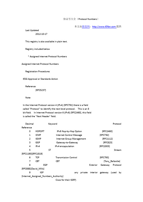
协议号大全(Protocol Numbers)本文由路饭网:提供Last Updated2012-10-17This registry is also available in plain text.Registry included below* Assigned Internet Protocol NumbersAssigned Internet Protocol NumbersRegistration ProceduresIESG Approval or Standards ActionReference[RFC5237]NoteIn the Internet Protocol version 4 (IPv4) [RFC791] there is a fieldcalled "Protocol" to identify the next level protocol. This is an 8bit field. In Internet Protocol version 6 (IPv6) [RFC2460], this fieldis called the "Next Header" field.Decimal Keyword Protocol Reference0 HOPOPT IPv6 Hop-by-Hop Option [RFC2460]1 ICMP Internet Control Message [RFC792]2 IGMP Internet Group Management [RFC1112]3 GGP Gateway-to-Gateway [RFC823]4 IPv4 IPv4 encapsulation [RFC2003]5 ST Stream [RFC1190][RFC1819]6 TCP Transmission Control [RFC793]7 CBT CBT [Tony_Ballardie]8 EGP Exterior Gateway Protocol [RFC888][David_Mills]9 IGP any private interior gateway (used by [Internet_Assigned_Numbers_Authority]Cisco for their IGRP)10 BBN-RCC-MON BBN RCC Monitoring [Steve_Chipman]11 NVP-II Network Voice Protocol [RFC741][Steve_Casner][Boggs, D., J. Shoch, E. Taft, and R. Metcalfe, "PUP: An Internetwork12 PUP PUP Architecture", XEROX Palo Alto Research Center, CSL-79-10, July 1979; also in IEEETransactions on Communication, Volume COM-28, Number 4, April 1980.][[XEROX]]13 ARGUS ARGUS [Robert_W_Scheifler]14 EMCON EMCON [<mystery contact>]15 XNET Cross Net Debugger [Haverty, J., "XNET Formats for Internet Protocol Version 4", IEN 158, October1980.][Jack_Haverty]16 CHAOS Chaos [J_Noel_Chiappa]17 UDP User Datagram [RFC768][Jon_Postel]18 MUX Multiplexing [Cohen, D. and J. Postel, "Multiplexing Protocol", IEN 90, USC/InformationSciences Institute, May 1979.][Jon_Postel]19 DCN-MEAS DCN Measurement Subsystems [David_Mills]20 HMP Host Monitoring [RFC869][Robert_Hinden]21 PRM Packet Radio Measurement [Zaw_Sing_Su]["The Ethernet, A Local Area Network: Data Link Layer and Physical LayerSpecification", AA-K759B-TK, Digital Equipment Corporation, Maynard, MA. Also as:"The Ethernet - A Local Area Network", Version 1.0, Digital Equipment Corporation,22 XNS-IDP XEROX NS IDP Intel Corporation, Xerox Corporation, September 1980. And: "The Ethernet, A LocalArea Network: Data Link Layer and Physical Layer Specifications", Digital, Inteland Xerox, November 1982. And: XEROX, "The Ethernet, A Local Area Network: DataLink Layer and Physical Layer Specification", X3T51/80-50, Xerox Corporation,Stamford, CT.,October 1980.][[XEROX]]23 TRUNK-1 Trunk-1 [Barry_Boehm]24 TRUNK-2 Trunk-2 [Barry_Boehm]25 LEAF-1 Leaf-1 [Barry_Boehm]26 LEAF-2 Leaf-2 [Barry_Boehm]27 RDP Reliable Data Protocol [RFC908][Robert_Hinden]28 IRTP Internet Reliable Transaction [RFC938][Trudy_Miller]29 ISO-TP4 ISO Transport Protocol Class 4 [RFC905][<mystery contact>]30 NETBLT Bulk Data Transfer Protocol [RFC969][David_Clark][Shuttleworth, B., "A Documentary of MFENet, a National Computer Network",31 MFE-NSP MFE Network Services Protocol UCRL-52317, Lawrence Livermore Labs, Livermore, California, June1977.][Barry_Howard]32 MERIT-INP MERIT Internodal Protocol [Hans_Werner_Braun]33 DCCP Datagram Congestion Control Protocol [RFC4340]34 3PC Third Party Connect Protocol [Stuart_A_Friedberg]35 IDPR Inter-Domain Policy Routing Protocol [Martha_Steenstrup]36 XTP XTP [Greg_Chesson]37 DDP Datagram Delivery Protocol [Wesley_Craig]38 IDPR-CMTP IDPR Control Message Transport Proto [Martha_Steenstrup]39 TP++ TP++ Transport Protocol [Dirk_Fromhein]40 IL IL Transport Protocol [Dave_Presotto]41 IPv6 IPv6 encapsulation [RFC2473]42 SDRP Source Demand Routing Protocol [Deborah_Estrin]43 IPv6-Route Routing Header for IPv6 [Steve_Deering]44 IPv6-Frag Fragment Header for IPv6 [Steve_Deering]45 IDRP Inter-Domain Routing Protocol [Sue_Hares]46 RSVP Reservation Protocol [RFC2205][RFC3209][Bob_Braden]47 GRE Generic Routing Encapsulation [RFC1701][Tony_Li]48 DSR Dynamic Source Routing Protocol [RFC4728]49 BNA BNA [Gary Salamon]50 ESP Encap Security Payload [RFC4303]51 AH Authentication Header [RFC4302]52 I-NLSP Integrated Net Layer Security TUBA [K_Robert_Glenn]53 SWIPE IP with Encryption [John_Ioannidis]54 NARP NBMA Address Resolution Protocol [RFC1735]55 MOBILE IP Mobility [Charlie_Perkins]56 TLSP Transport Layer Security Protocol [Christer_Oberg]using Kryptonet key management57 SKIP SKIP [Tom_Markson]58 IPv6-ICMP ICMP for IPv6 [RFC2460]59 IPv6-NoNxt No Next Header for IPv6 [RFC2460]60 IPv6-Opts Destination Options for IPv6 [RFC2460]61 any host internal protocol [Internet_Assigned_Numbers_Authority]62 CFTP CFTP [Forsdick, H., "CFTP", Network Message, Bolt Beranek and Newman, January1982.][Harry_Forsdick]63 any local network [Internet_Assigned_Numbers_Authority]64 SAT-EXPAK SATNET and Backroom EXPAK [Steven_Blumenthal]65 KRYPTOLAN Kryptolan [Paul Liu]66 RVD MIT Remote Virtual Disk Protocol [Michael_Greenwald]67 IPPC Internet Pluribus Packet Core [Steven_Blumenthal]68 any distributed file system [Internet_Assigned_Numbers_Authority]69 SAT-MON SATNET Monitoring [Steven_Blumenthal]70 VISA VISA Protocol [Gene_Tsudik]71 IPCV Internet Packet Core Utility [Steven_Blumenthal]72 CPNX Computer Protocol Network Executive [David Mittnacht]73 CPHB Computer Protocol Heart Beat [David Mittnacht]74 WSN Wang Span Network [Victor Dafoulas]75 PVP Packet Video Protocol [Steve_Casner]76 BR-SAT-MON Backroom SATNET Monitoring [Steven_Blumenthal]77 SUN-ND SUN ND PROTOCOL-Temporary [William_Melohn]78 WB-MON WIDEBAND Monitoring [Steven_Blumenthal]79 WB-EXPAK WIDEBAND EXPAK [Steven_Blumenthal]80 ISO-IP ISO Internet Protocol [Marshall_T_Rose]81 VMTP VMTP [Dave_Cheriton]82 SECURE-VMTP SECURE-VMTP [Dave_Cheriton]83 VINES VINES [Brian Horn]84 TTP TTP [Jim_Stevens]84 IPTM Protocol Internet Protocol Traffic [Jim_Stevens]Manager85 NSFNET-IGP NSFNET-IGP [Hans_Werner_Braun]86 DGP Dissimilar Gateway Protocol [M/A-COM Government Systems, "Dissimilar Gateway Protocol Specification, DraftVersion", Contract no. CS901145, November 16, 1987.][Mike_Little]87 TCF TCF [Guillermo_A_Loyola]88 EIGRP EIGRP [Cisco Systems, "Gateway Server Reference Manual", Manual Revision B, January 10,1988.][Guenther_Schreiner]89 OSPFIGP OSPFIGP [RFC1583][RFC2328][RFC5340][John_Moy][Welch, B., "The Sprite Remote Procedure Call System", Technical Report,90 Sprite-RPC Sprite RPC Protocol UCB/Computer Science Dept., 86/302, University of California at Berkeley, June1986.][Bruce Willins]91 LARP Locus Address Resolution Protocol [Brian Horn]92 MTP Multicast Transport Protocol [Susie_Armstrong]93 AX.25 AX.25 Frames [Brian_Kantor]94 IPIP IP-within-IP Encapsulation Protocol [John_Ioannidis]95 MICP Mobile Internetworking Control Pro. [John_Ioannidis]96 SCC-SP Semaphore Communications Sec. Pro. [Howard_Hart]97 ETHERIP Ethernet-within-IP Encapsulation [RFC3378]98 ENCAP Encapsulation Header [RFC1241][Robert_Woodburn]99 any private encryption scheme [Internet_Assigned_Numbers_Authority]100 GMTP GMTP [[RXB5]]101 IFMP Ipsilon Flow Management Protocol [Bob_Hinden][November 1995, 1997.]102 PNNI PNNI over IP [Ross_Callon]103 PIM Protocol Independent Multicast [RFC4601][Dino_Farinacci]104 ARIS ARIS [Nancy_Feldman] 105 SCPS SCPS [Robert_Durst] 106 QNX QNX [Michael_Hunter]107 A/N Active Networks [Bob_Braden]108 IPComp IP Payload Compression Protocol [RFC2393]109 SNP Sitara Networks Protocol [Manickam_R_Sridhar]110 Compaq-Peer Compaq Peer Protocol [Victor_Volpe]111 IPX-in-IP IPX in IP [CJ_Lee]112 VRRP Virtual Router Redundancy Protocol [RFC5798]113 PGM PGM Reliable Transport Protocol [Tony_Speakman]114 any 0-hop protocol [Internet_Assigned_Numbers_Authority]115 L2TP Layer Two Tunneling Protocol [RFC3931][Bernard_Aboba]116 DDX D-II Data Exchange (DDX) [John_Worley]117 IATP Interactive Agent Transfer Protocol [John_Murphy]118 STP Schedule Transfer Protocol [Jean_Michel_Pittet] 119 SRP SpectraLink Radio Protocol [Mark_Hamilton]120 UTI UTI [Peter_Lothberg] 121 SMP Simple Message Protocol [Leif_Ekblad]122 SM SM [Jon_Crowcroft]123 PTP Performance Transparency Protocol [Michael_Welzl]124 ISIS over IPv4 [Tony_Przygienda]125 FIRE [Criag_Partridge] 126 CRTP Combat Radio Transport Protocol [Robert_Sautter]127 CRUDP Combat Radio User Datagram [Robert_Sautter] 128 SSCOPMCE [Kurt_Waber] 129 IPLT [[Hollbach]]130 SPS Secure Packet Shield [Bill_McIntosh]131 PIPE Private IP Encapsulation within IP [Bernhard_Petri]132 SCTP Stream Control Transmission Protocol [Randall_R_Stewart]133 FC Fibre Channel [Murali_Rajagopal][RFC6172]134 RSVP-E2E-IGNORE [RFC3175]135 Mobility Header [RFC6275]136 UDPLite [RFC3828]137 MPLS-in-IP [RFC4023]138 manet MANET Protocols [RFC5498]139 HIP Host Identity Protocol [RFC5201]140 Shim6 Shim6 Protocol [RFC5533]141 WESP Wrapped Encapsulating Security [RFC5840]Payload142 ROHC Robust Header Compression [RFC5858]143-252 Unassigned [Internet_Assigned_Numbers_Authority]253 Use for experimentation and testing [RFC3692]254 Use for experimentation and testing [RFC3692]255 Reserved [Internet_Assigned_Numbers_Authority]PeopleID Name Contact URI Last Updated[Barry_Boehm] Barry Boehm mailto:boehm&[Barry_Howard] Barry Howard mailto:Howard&[Bernard_Aboba] Bernard Aboba mailto:bernarda& 1998-04[Bernhard_Petri] Bernhard Petri mailto:bernhard.petri& 2012-07-09[Bill_McIntosh] Bill McIntosh mailto:BMcIntosh&[Bob_Braden] Bob Braden mailto:braden& 1997-07[Bob_Hinden] Bob Hinden mailto:hinden&[Brian_Kantor] Brian Kantor mailto:brian&[CJ_Lee] CJ Lee mailto:cj_lee& 1997-10[Charlie_Perkins] Charlie Perkins mailto:perk& 1994-10[Christer_Oberg] Christer Oberg mailto:chg&bull.se 1994-10[Criag_Partridge] Criag Partridge mailto:craig& 1999-08[Dave_Cheriton] Dave Cheriton mailto:cheriton&[Dave_Presotto] Dave Presotto mailto:presotto& 1995-07[David_Clark] David Clark mailto:ddc&[David_Mills] David Mills mailto:Mills&[Deborah_Estrin] Deborah Estrin mailto:estrin&[Dino_Farinacci] Dino Farinacci mailto:dino& 1996-03[Dirk_Fromhein] Dirk Fromhein mailto:df&[Gene_Tsudik] Gene Tsudik mailto:tsudik&[Greg_Chesson] Greg Chesson mailto:Greg&[Guenther_Schreiner] Guenther Schreiner mailto:snmp-admin&a.de[Guillermo_A_Loyola] Guillermo A. Loyola mailto:LOYOLA&[Hans_Werner_Braun] Hans-Werner Braun mailto:HWB&[Harry_Forsdick] Harry Forsdick mailto:Forsdick&[Howard_Hart] Howard Hart mailto:hch&[Internet_Assigned_Numbers_Authority] Internet Assigned Numbers Authority mailto:iana& 1995-06[J_Noel_Chiappa] J. Noel Chiappa mailto:JNC&[Jack_Haverty] Jack Haverty mailto:jhaverty&[Jean_Michel_Pittet] Jean-Michel Pittet mailto:jmp& 1998-11[Jim_Stevens] Jim Stevens mailto:jasteven& 2011-01-26[John_Ioannidis] John Ioannidis mailto:ji&[John_Moy] John Moy mailto:jmoy&[John_Murphy] John Murphy mailto:john.m.murphy& 1998-10[John_Worley] John Worley mailto:worley& 1998-06[Jon_Crowcroft] Jon Crowcroft mailto:jon& 1999-06[Jon_Postel] Jon Postel mailto:postel&[K_Robert_Glenn] K. Robert Glenn mailto:glenn&[Kurt_Waber] Kurt Waber mailto:kurt.waber& 1999-08[Leif_Ekblad] Leif Ekblad mailto:leif& 2012-08-21[Manickam_R_Sridhar] Manickam R. Sridhar mailto:msridhar& 1997-09[Mark_Hamilton] Mark Hamilton mailto:mah& 1998-11[Marshall_T_Rose] Marshall T. Rose mailto:mrose&[Martha_Steenstrup] Martha Steenstrup mailto:MSteenst&[Michael_Greenwald] Michael Greenwald mailto:Greenwald&[Michael_Hunter] Michael Hunter mailto:mphunter& 1997-07[Michael_Welzl] Michael Welzl mailto:michael&tk.uni-linz.ac.at 1999-08[Mike_Little] Mike Little mailto:little&macom4.arpa[Murali_Rajagopal] Murali Rajagopal mailto:murali& 2000-05[Nancy_Feldman] Nancy Feldman mailto:nkf& 1997-01[Peter_Lothberg] Peter Lothberg mailto:roll&stupi.se 1999-03[Randall_R_Stewart] Randall R. Stewart mailto:rrs& 2000-04[Robert_Durst] Robert Durst mailto:durst& 1997-03[Robert_Hinden] Robert Hinden mailto:Hinden&[Robert_Sautter] Robert Sautter mailto:rsautter& 1999-08[Robert_W_Scheifler] Robert W. Scheifler mailto:RWS&[Robert_Woodburn] Robert Woodburn mailto:woody&[Ross_Callon] Ross Callon mailto:rcallon& 1995-12[Steve_Casner] Steve Casner mailto:casner&[Steve_Chipman] Steve Chipman mailto:Chipman&[Steve_Deering] Steve Deering mailto:deering& 1995-03[Steven_Blumenthal] Steven Blumenthal mailto:BLUMENTHAL&[Stuart_A_Friedberg] Stuart A. Friedberg mailto:stuart&[Sue_Hares] Sue Hares mailto:skh&[Susie_Armstrong] Susie Armstrong mailto:Armstrong.wbst128&[Tom_Markson] Tom Markson mailto:markson& 1995-09[Tony_Ballardie] Tony Ballardie mailto:A.Ballardie&[Tony_Li] Tony Li mailto:tony.li&tony.li 2012-10-17[Tony_Przygienda] Tony Przygienda mailto:prz& 1999-08[Tony_Speakman] Tony Speakman mailto:speakman& 1998-01[Trudy_Miller] Trudy Miller mailto:Trudy&[Victor_Volpe] Victor Volpe mailto:vvolpe& 1997-10[Wesley_Craig] Wesley Craig mailto:Wesley.Craig&[William_Melohn] William Melohn mailto:Melohn&[Zaw_Sing_Su] Zaw-Sing Su mailto:ZSu&tsca.istc.sri.。
rohc压缩算法

ROHC压缩算法:低带宽环境下的IP数据流传输优
化技术
ROHC(Robust Header Compression)是一种用于IP数据流的头压缩协议,旨在减少IP头部的开销,从而提高传输效率。
它主要应用于无线和低带宽网络环境中,在这些环境中,数据传输的带宽非常有限,因此减少头部开销可以大大提高传输效率。
ROHC压缩算法主要通过预测和压缩IP头部的静态信息来实现减小头部开销的目标。
它采用了多种压缩技术,包括:
1.符号表匹配:ROHC使用符号表来压缩头部中的某些值。
当遇到已知的值
时,直接用符号表示,从而减少传输的数据量。
2.上下文建模:ROHC使用上下文建模技术来预测头部中的下一个值。
通过
利用已经接收到的头部信息,ROHC可以预测下一个值,从而减少需要传输的数据量。
3.差分编码:当头部的某些值发生变化时,ROHC使用差分编码技术来仅传
输差分信息。
这样可以避免重复传输相同的数据,从而减少数据传输量。
4.解压缩状态机:ROHC的解压状态机是根据压缩状态机设计的。
解压状态
机接收压缩数据并根据上下文信息将它们解码为原始头部数据。
总的来说,ROHC压缩算法是一种有效的头压缩技术,能够在低带宽和无线环境中显著提高IP数据流的传输效率。
- 1、下载文档前请自行甄别文档内容的完整性,平台不提供额外的编辑、内容补充、找答案等附加服务。
- 2、"仅部分预览"的文档,不可在线预览部分如存在完整性等问题,可反馈申请退款(可完整预览的文档不适用该条件!)。
- 3、如文档侵犯您的权益,请联系客服反馈,我们会尽快为您处理(人工客服工作时间:9:00-18:30)。
Network Working Group G. Pelletier Request for Comments: 4224 L-E. Jonsson Category: Informational K. Sandlund Ericsson January 2006 RObust Header Compression (ROHC):ROHC over Channels That Can Reorder PacketsStatus of This MemoThis memo provides information for the Internet community. It doesnot specify an Internet standard of any kind. Distribution of thismemo is unlimited.Copyright NoticeCopyright (C) The Internet Society (2006).AbstractRObust Header Compression (ROHC), RFC 3095, defines a framework forheader compression, along with a number of compression protocols(profiles). One operating assumption for the profiles defined in RFC 3095 is that the channel between compressor and decompressor isrequired to maintain packet ordering. This document discussesaspects of using ROHC over channels that can reorder packets. Itprovides guidelines on how to implement existing profiles over suchchannels, as well as suggestions for the design of new profiles. Pelletier, et al. Informational [Page 1]Table of Contents1. Introduction (3)2. Terminology (4)3. Applicability of This Document to ROHC Profiles (5)3.1. Profiles within Scope (5)3.2. Profiles with Special Considerations (5)3.3. Profiles Incompatible with Reordering (6)4. Background (6)4.1. Reordering Channels (6)4.2. Robustness Principles of ROHC (6)4.2.1. Optimistic Approach (U/O-mode) (7)4.2.2. Secure Reference Principle (R-mode) (7)5. Problem Description (7)5.1. ROHC and Reordering Channels (7)5.1.1. LSB Interpretation Interval and Reordering (7)5.1.2. Reordering of Packets in R-mode (9)5.1.2.1. Updating Packets (9)5.1.2.2. Non-Updating Packets (10)5.1.3. Reordering of Packets in U/O-mode (10)5.1.4. Reordering on the Feedback Channel (11)5.1.5. List Compression (11)5.1.6. Reordering and Mode Transitions (12)5.2. Consequences of Reordering (13)5.2.1. Functionality Incompatible with Reordering (13)5.2.2. Context Damage (Loss of Synchronization) (13)5.2.3. Detected Decompression Failures (U/O/R-mode) (13)5.2.4. Undetected Decompression Failures (R-mode only) (14)6. Making ROHC Tolerant against Reordering (14)6.1. Properties of ROHC Implementations (14)6.1.1. Compressing Headers with Robustness againstReordering (14)6.1.1.1. Reordering and the Optimistic Approach (15)6.1.1.2. Reordering and the SecureReference Principle (15)6.1.1.3. Robust Selection of Compressed Header (15)6.1.2. Implementing a Reordering-Tolerant Decompressor (16)6.1.2.1. Decompressor Feedback Considerations (16)6.1.2.2. Considerations for Local RepairMechanisms (17)6.2. Specifying ROHC Profiles with Robustness againstReordering (17)6.2.1. Profiles with Interpretation IntervalOffset p = -1 (17)6.2.2. Modifying the Interpretation Interval Offset (18)6.2.2.1. Example Profile for Handling Reordering (18)6.2.2.2. Defining the Values of p for NewProfiles (18)Pelletier, et al. Informational [Page 2]7. Security Considerations (19)8. Acknowledgements (19)9. Informative References (19)1. IntroductionRObust Header Compression (ROHC), RFC 3095 [1], defines a frameworkfor header compression, along with a number of compression protocols (profiles). One operating assumption for the profiles defined in RFC 3095 is that the channel between compressor and decompressor isrequired to maintain packet ordering for each compressed flow. Themotivation behind this assumption was that the primary candidatechannels considered did guarantee in-order delivery of header-compressed packets. This assumption made it possible to meet thedesign objectives that were on top of the requirements list at thetime when ROHC was being designed, namely to improve the compression efficiency and the tolerance to packet losses.Since the publication of RFC 3095 in 2001, the question about ROHCoperation over channels that do not guarantee in-order delivery hassurfaced several times; arguments that ROHC cannot perform adequately over such channels have been heard. Specifically, this has beenraised as a weakness when compared to other header compressionalternatives, as RFC 3095 explicitly states its inability to operate if in-order delivery is not guaranteed. For those familiar with the details of ROHC and of other header compression schemes, it is clear that this is a misconception, but it can also be easily understoodthat the wording used in RFC 3095 can lead to such interpretation.This document discusses the various aspects of implementing ROHC over channels that can reorder header-compressed packets. It explainsdifferent ways of implementing the profiles found in RFC 3095, aswell as other profiles based on those profiles, over reorderingchannels. This can be achieved either by ensuring that compressorimplementations use compressed headers that are sufficiently robustto the expected possible reordering and/or by modifying decompressor implementations to tolerate reordered packets. Ideas regarding howexisting profiles could be updated and how new profiles can bedefined to cope efficiently with reordering are also discussed.In some scenarios, there might be external means (such as a sequence number) to detect and potentially correct reordering. That is, forexample, the case when running compression over an IPsecEncapsulating Security Payload (ESP) tunnel. With such externalmeans to detect reordering, the decompressor can be modified to make use of the external information provided, and reordering can then be handled. How to make use of external means to address reordering is, however, out of scope for this document.Pelletier, et al. Informational [Page 3]2. TerminologyThis document uses terminology consistent with RFC 3759 [2], and isin itself only informative. Although it does discuss technicalaspects of implementing the ROHC specifications in particularenvironments, it does not specify any new technology.ROHCThe term "ROHC" herein refers to the following profiles:- 0x0001, 0x0002, and 0x0003 defined in RFC 3095 [1];- 0x0004 for compression of IP-only headers [3];- 0x0007 and 0x0008 for compression of UDP-Lite headers [4].The term "ROHC" excludes the following profiles, which are either not affected by reordering or have the assumption of in-orderdelivery as a fundamental requirement for their proper operation: - 0x0000 (uncompressed) [1];- 0x0005 (Link-Layer Assisted (LLA)) [5] and 0x0105(R-mode extension to LLA) [6];ReorderingA type of transmission taking place between compressor anddecompressor where in-order delivery of header-compressed packets is not guaranteed.Reordering channelA connection over which reordering, as defined above, can occur.Sequentially early packetA packet that reaches the decompressor before one or severalpackets of the same context identifier (CID) that were delayed on the link. At the time of the arrival of a sequentially earlypacket, the packet(s) delayed on the link cannot be differentiated from lost packet(s).Sequentially late packetA packet is late within its sequence if it reaches thedecompressor after one or several other packets belonging to thesame CID have been received, although the sequentially late packet was sent from the compressor before the other packet(s).Pelletier, et al. Informational [Page 4]Updating packetA packet that updates the context of the decompressor, e.g., allpackets except R-0 and R-1* in RFC 3095 [1].Non-updating packetA packet that does not update the context of the decompressor,e.g., only R-0 and R-1* in RFC 3095 [1].Change packetA packet that updates one or more fields of the context other than the fields pertaining to the functions established with respect to the sequence number (SN). Specifically, it is a packet thatupdates fields other than the SN, the IPv4 identifier (IP-ID), the sequence number of an extension header or the RTP timestamp (TS).3. Applicability of This Document to ROHC ProfilesThis document addresses general reordering issues for ROHC profiles. The foremost objectives are to ensure that ROHC implementations donot forward packets with incorrectly decompressed headers to upperlayers, as well as to limit the possible increase in the rate ofdecompression failures or in events leading to context damage, whencompression is applied over reordering channels.3.1. Profiles within ScopeThe following sections outline solutions that are generallyapplicable to profiles 0x0001 (RTP), 0x0002 (UDP), and 0x0003 (ESP)defined in RFC 3095 [1]. Profile 0x0000 (uncompressed) is notaffected by reordering, as the headers are sent uncompressed. Thesolutions also apply to profiles for IP-only (0x0004) [3] and forUDP-Lite (0x0007 and 0x0008) [4]. These profiles are based on theprofiles of RFC 3095 [1] and inherently make the same in-orderdelivery assumption.3.2. Profiles with Special ConsiderationsSpecial considerations are needed to make some of the implementation solutions of sections 6.1 and 6.2 applicable to profiles 0x0002 (UDP) [1], 0x0004 (IP-only) [3], and 0x0008 (UDP-Lite) [4]. For theseprofiles, the SN is generated at the compressor, as it is not present in headers being compressed. For the least significant bit (LSB)encoding method, the interpretation interval offset (p) is alwaysp = -1 (see section 5.1.1) when interpreting the SN. The SN is thus Pelletier, et al. Informational [Page 5]required to increase for each packet received at the decompressor,which means that reordered packets cannot be decompressed.3.3. Profiles Incompatible with ReorderingThe ROHC LLA profiles defined in RFC 3242 [5] and RFC 3408 [6] havebeen explicitly designed with in-order delivery as a fundamentalrequirement to their proper operation. Profiles 0x0005 and 0x0105can therefore not be implemented over channels where reordering canoccur; this document therefore does not apply to these profiles.4. BackgroundROHC was designed with the assumption that packets are delivered inorder from compressor to decompressor. This was considered as areasonable working assumption for links where it was expected thatROHC would be used. However, many have expressed that it would bedesirable to use ROHC also over connections where in-order deliveryis not guaranteed [7].4.1. Reordering ChannelsThe reordering channels that are potential candidates to use ROHC are single-hop channels and multi-hop virtual channels.A single-hop channel is a point-to-point link that constitutes asingle IP hop. Note that one IP hop could be one or multiplephysical links. For example, a single-hop reordering channel couldbe a wireless link that applies error detection and performsretransmissions to guarantee error-free delivery of all data.Another example could be a wireless connection that performsbicasting of data during a handoff procedure.A multi-hop virtual channel is a virtual point-to-point link thattraverses multiple IP hops. A multi-hop virtual channel wouldtypically be an IP tunnel, where compression is applied over thetunnel by the endpoints of the tunnel (not to be confused with single link compression of tunneled packets).4.2. Robustness Principles of ROHCRobustness is based on the optimistic approach in the unidirectional and optimistic modes of operation (U/O-mode), and on the securereference principle in the bidirectional reliable mode (R-mode).Both approaches have different characteristics in the presence ofreordering between compressor and decompressor. However, in anymode, decompression of sequentially early packets will generally be Pelletier, et al. Informational [Page 6]handled quite well since they will be perceived and treated by thedecompressor as if there had been one or more packet losses.4.2.1. Optimistic Approach (U/O-mode)A ROHC compressor uses the optimistic approach to reduce headeroverhead when performing context updates in U/O-mode. The compressor normally repeats the same update until it is fairly confident thatthe decompressor has successfully received the information. Thenumber of consecutive packets needed to obtain this confidence isopen to implementations, and this number is normally related to thepacket loss characteristics of the link where header compression isused (see also [1], section 5.3.1.1.1).All packet types used in U/O-mode are context updating.4.2.2. Secure Reference Principle (R-mode)A ROHC compressor uses the secure reference principle in R-mode toensure that context synchronization between ROHC peers cannot be lost due to packet losses. The compressor obtains its confidence that the decompressor has successfully updated the context from a packetcarrying a 7- or 8-bit Cyclic Redundancy Check (CRC) based onacknowledgements received from the decompressor (see also [1],section 5.5.1.2).The secure reference principle makes it possible for a compressor to use packets that do not update the context (i.e., R-0 and R-1* [1]).5. Problem Description5.1. ROHC and Reordering ChannelsThis section reviews different aspects of ROHC susceptible of beingimpacted by reordering of compressed packets between ROHC peers.5.1.1. LSB Interpretation Interval and ReorderingThe least significant bit (LSB) encoding method defined in RFC 3095([1], section 5.7) specifies the interpretation interval offset,called p, as follows:For profiles 0x0001, 0x0003, and 0x0007:p = 1, when bits(SN) <= 4;p = 2^(bits(SN)-5) - 1 otherwise.Pelletier, et al. Informational [Page 7]The resulting table describing the interpretation interval is asfollows:+-----------+--------------+--------------+| bits (SN) | Offset p | (2^k-1) - p || k | (reordering) | (losses) |+-----------+--------------+--------------+| 4 | 1 | 14 || 5 | 0 | 31 || 6 | 1 | 62 || 7 | 3 | 124 || 8 | 7 | 248 || 9 | 15 | 496 |+-----------+--------------+--------------+As shown in the table above, the ability for ROHC to handlesequentially late packets depends on the number of bits sent ineach packet. For example, a sequentially late packet of type 0(with either 4 or 6 bits of SN) sets the limit to one packet outof sequence for successful decompression to be possible.For profiles 0x0002, 0x0004, and 0x0008:p = - 1, independently of bits(SN).A value of p = -1 means that the interpretation interval offsetcan only take positive values and that no sequentially late packet can be decompressed if reordering occurs over the link.The trade-off between reordering and robustnessThe ability of ROHC to handle sequentially late packets is limited by the interpretation interval offset of the sliding window usedfor LSB encoding. This offset has a very small value for packets with a small number of sequence number (SN) bits, but grows withthe number of SN bits transmitted.For channels where both packet losses and reordering can occur,modifications to the interpretation interval face a trade-offbetween the amount of reordering and the number of consecutivepacket losses that can be handled by the decompressor. If thenegative offset (i.e., p) is increased to handle a larger amountof reordering, the value of the positive offset of theinterpretation interval must be decreased. This may impact thecompression efficiency when the channel has a high loss rate. Pelletier, et al. Informational [Page 8]This is shown in the figure:<--- interpretation interval (size is 2^k) ---->|------------------+---------------------------|Lower v_ref UpperBound Bound<--- reordering --> <--------- losses --------->max delta(SN) = p max delta(SN) = (2^k-1) - pwhere v_ref is the reference value as per [1], section 4.5.1.In practice, the maximum variation in SN value (max delta(SN)) due to reordering that can be handled will normally correspond to the maximum number of packets that can be reordered. The same applies to the maximum number of consecutive packet losses covered by the robustness interval.Timer-based compression of RTP TS (see [1], section 4.5.4) providesmeans to reduce the number of timestamp bits needed in compressedheaders after longer gaps in the packet stream (e.g., for an audiostream, this is typically due to silence suppression). To usetimer-based compression, an upper limit on the inter-arrival jittermust be reliably estimated by the compressor. It should be notedthat although the risk of reordering of course means there is a more significant jitter on the path between the compressor and thedecompressor, there are no special reordering considerations fortimer-based compression. It all still boils down to the task ofestimating the jitter, requiring channel characteristics knowledge at the compressor, and/or jitter estimation figures received from thedecompressor.5.1.2. Reordering of Packets in R-mode5.1.2.1. Updating PacketsThe compressor always adds references in the sliding window for allupdating packets sent. The compressor removes values older thanvalues for which it has received an acknowledgement to shrink thewindow and thereby increase the compression efficiency.The decompressor always updates the context when receiving anupdating packet and uses the new reference for decompression.Acknowledgements are sent to allow the compressor to shrink itssliding window.Pelletier, et al. Informational [Page 9]Reordering between updating packetsThe decompressor can update its context from the reception of asequentially late updating packet. The decompressor reference is then updated with a value that is no longer in the sliding window of the compressor. This "missing reference" can be caused byreordering when operating in R-mode.The result is that the compressor and the decompressor losesynchronization with each other. When the decompressoracknowledges the sequentially late packet, the compressor mightalready have discarded the reference to this sequence number, and continue to compress packets based on more recent references (inpacket arrival time). Decompression will then be attempted using the wrong reference.5.1.2.2. Non-Updating PacketsReordering between non-updating packets onlyA non-updating packet that reaches the decompressor out ofsequence only with respect to other non-updating packets canalways be decompressed properly.Reordering between non-updating packets and updating packetsWhen a non-updating packet is reordered and becomes sequentiallylate with respect to an updating packet, the decompressor may have already updated the context with a new reference when the latepacket is received. It is thus possible for a non-updating packet to be decompressed based on the wrong reference because ofreordering when operating in R-mode.Since decompression of non-updating packets cannot be verified,this can lead to a packet erroneously decompressed to be forwarded to upper layers.5.1.3. Reordering of Packets in U/O-modeReordering between non-change packets onlyWhen only non-change packets are reordered with respect to eachother, decompression of sequentially late packets is limited bythe offset p of the interpretation interval (see section 5.1.1).Decompression of a sequentially late packet with SN = x ispossible if the value of the SN of the packet that last updatedthe context was less than or equal to x + p.Pelletier, et al. Informational [Page 10]Problems occur if context(SN) has increased by more than p withrespect to field(SN) carried within the packet to decompress.This means that for a well-behaved stream with a constant unitincrease in the RTP SN, a packet can arrive up to p packets out of sequence and still be correctly decompressed. Otherwise, itcannot be properly decompressed. It also means that if thecompressor sends two consecutive packets with SN(packet1)=100 and SN(packet2)=108 when p=7, packet1 cannot be decompressed if itarrives even one packet late due to reordering.Reordering involving change packetsWhen a packet is reordered and becomes sequentially late withrespect to a change packet, decompression of the late packet mayeventually fail, as the context information required forsuccessful decompression may not be available anymore.Decompression can always be verified since all U/O-mode packet types are context updating. Consequently, a failure to decompress a packet that is caused by reordering can be detected, and contextinvalidation due to reordering can thus be avoided. The risk offorwarding incorrectly decompressed packets to upper layers istherefore small when operating in U/O-mode. For channels known toreorder packets, U/O-mode should therefore be the preferred mode ofoperation. The additional risk of losing context synchronization, or for erroneous packet to be delivered to upper layers, is limited.5.1.4. Reordering on the Feedback ChannelFor R-mode, upon reception of an acknowledgement, the compressorsearches the sliding window to locate an updating packet with thecorresponding SN; if it is not found, the acknowledgement is invalid and is discarded ([1], section 5.5.1.2). In other words, feedbackreceived out of order either is still useful or is discarded.In U/O-mode, if the compressor updates its context based on feedback, the same logic as for R-mode applies in practice.Reordering on the feedback channel has thus no impact in either mode.5.1.5. List CompressionROHC list compression is an additional compression scheme for RTPcontributing source (CSRC) lists and IP extension header chains. The base is called table-based item compression, and it is almostcompletely independent from the rest of the ROHC compression logic.Therefore, this part of the scheme does not exhibit any special Pelletier, et al. Informational [Page 11]vulnerabilities when it comes to reordering, assuming a reasonableoptimistic approach is used in U/O-mode. Specifically, it does notsuffer significantly from the "missing reference" problem whenoperating in R-mode.On top of the table-based item compression mechanism, an additionalcompression technique may be used, called reference based listcompression. Reference based list compression however has a logicthat is similar to the rest of the ROHC compression logic, andtherefore it suffers from similar reordering vulnerabilities,especially the "missing reference" problem of R-mode. Note, however, that the generation identifier used in U/O-mode makes that schememore robust to reordering.When using list encoding type 1, 2, or 3, which makes use ofreference lists, decompression will succeed only if all individualitems are known by the decompressor, along with the correct reference list required to properly decompress the packet. List compressionusing the "Generic scheme", also known as "Encoding type 0", is notusing reference based list compression, and type 0 decompression will thus succeed as long as all individual items are known by thedecompressor. Because of this, type 0 list compression should be the preferred method used when operating over reordering channels.5.1.6. Reordering and Mode TransitionsTransition from U/O-mode to R-modeThis transition can be affected by reordering if a packet type 0(UO-0) is reordered and delayed by at least one round-trip time(RTT). If the decompressor initiates a mode change request toR-mode in the meantime, the reordered UO-0 packet may be handledas an R-0 packet; it can be erroneously decompressed and forwarded to upper layers. This is because the decompressor can switch toR-mode as soon as it sends the acknowledgement Ack(SN, R) to thecompressor (see also [1], section 5.6).Transition from R-mode to U/O-modeA similar situation as above can occur during this transition.However, because the outcome of the decompression is alwaysverified using a CRC verification in U/O-mode, the reorderedpacket will most likely fail decompression and will be discarded. The above situation, although it is not deemed to occur frequently,is still possible; thus, mode transitions from U/O-mode to R-modeshould be avoided when reordering can occur.Pelletier, et al. Informational [Page 12]5.2. Consequences of ReorderingThe context updating properties of the packets exchanged between ROHC peers are the most important factors to consider when deriving theimpacts of reordering. For this reason, the robustness properties of the U/O-mode and of the R-mode are affected differently.The effects of reordering on ROHC can be summarized as follows:- Functionality incompatible with reordering;- Increased probability of context damage (loss of synchronization); - Increased number of decompression failures - Detected (U/O/R-mode); - Increased number of decompression failures - Undetected (R-mode).5.2.1. Functionality Incompatible with ReorderingThere is one optional ROHC function that cannot work in the presence of reordering between ROHC peers.The ROHC segmentation scheme (see [1], section 5.2.5) relies entirely on the in-order delivery of each segment, as there is no sequencinginformation in the segments. A segmented packet for which one (ormore) segment is received out of order cannot be decompressed, and it is discarded by the decompressor. Therefore, segmentation should not be used if there can be reordering between the ROHC peers.The use of this optional feature is open to implementations and islocal to the compressor only; it does not impact the decompressor.5.2.2. Context Damage (Loss of Synchronization)Reordering of packets between ROHC peers can impact the robustnessproperties of the optimistic approach (U/O-mode) as well as thereliability of the secure reference principle (R-mode).The successful decompression of a sequentially late change packet(U/O-mode) and/or updating packet (R-mode) can update the context of the decompressor in a manner unexpected by the compressor. This can lead to a loss of context synchronization between the ROHC peers.5.2.3. Detected Decompression Failures (U/O/R-mode)Reordering of packets between ROHC peers can lead to an increase inthe number of decompression failures for context updating packets(see sections 5.1.2.1 and 5.1.3). Fortunately, as the outcome of the decompression of updating packets can be verified, the decompressorcan reliably detect decompression failures, including those caused by reordering, and discard the packet. Note that local repairs, subject Pelletier, et al. Informational [Page 13]to the limitations stated in [1] section 5.3.2.2.3, can still beperformed.5.2.4. Undetected Decompression Failures (R-mode only)Reordering of packets between ROHC peers can lead to an increase inthe number of decompression errors for non-updating packets. ForR-mode, decompression of R-0 and R-1* packets cannot be verified. If reordering occurs and decompression is performed using the wrongsecure reference (see section 5.1.2.1 and 5.1.2.2), the decompressor cannot reliably detect such errors. As a result, erroneous packetsmay be forwarded to upper layers.6. Making ROHC Tolerant against ReorderingThis section describes different approaches that can improve theperformance of ROHC when used over reordering channels and minimizethe effects of reordering. Examples are provided to guideimplementers and designers of new profiles. The solutions targeteither the properties of ROHC implementations or the specification of profiles. This is covered by sections 6.1 and 6.2, respectively.6.1. Properties of ROHC ImplementationsExisting ROHC profiles can be implemented with the capability toproperly handle packet reordering. The methods described in thissection conform with, and thus do not require any modifications to,the ROHC specifications within scope of this document (see section3). Specifically, the methods presented in this section can beimplemented without any impairment to interoperability with otherROHC implementations that do not use these methods.The methods suggested here may, however, lower the compressionefficiency, and these modifications should not be used whenreordering is known not to occur. Some of these methods aim toincrease the decompression success rate at the decompressor, whileothers aim to avoid context damage that would cause a loss of context synchronization between compressor and decompressor.The methods proposed are each addressing specific issues listed insection 5 and can be combined to achieve better robustness againstreordering.6.1.1. Compressing Headers with Robustness against ReorderingThe methods described in this section are methods local only to thecompressor implementation. They can be used without modifications or impact to the decompressor.Pelletier, et al. Informational [Page 14]。