06349lec3a
Power Circuit and Motor-mounted Apparatus Certifie

Power Circuit and Motor-mounted Apparatus Certified for CanadaAccessories, "Inrush Limiter SITOP Series", Model(s) 6EP1967-2AA00 Accessories , Model(s) 6EP4134-3AB00-0AY0, 6EP4134-3AB00-1AY0, 6EP4134-3AB00-2AY0, 6EP4136-3AB00-0AY0, 6EP4136-3AB00-1AY0, 6EP4136-3AB00-2AY0, 6EP4137-3AB00-0AY0, 6EP4137-3AB00-1AY0, 6EP4137-3AB00-2AY0Industrial control equipment, miscellaneous apparatus , Model(s) 6EP1333-1AL12, 6EP1333-3BA00, 6EP1333-3BA00-8AC0, 6EP1334-1AL12, 6EP1334-3BA00, 6EP1334-3BA00-8AB0, 6EP1336-2BA10, 6EP1336-3BA00, 6EP1336-3BA00-8AA0, 6EP1336-3BA10, 6EP1337-3BA00, 6EP1424-3BA00, 6EP1433-0AA00, 6EP1434-2BA10, 6EP1436-2BA10, 6EP1436-3BA00, 6EP1436-3BA00-8AA0, 6EP1436-3BA01, 6EP1436-3BA10, 6EP1437-2BA20, 6EP1437-3BA00, 6EP1437-3BA00-0AA0, 6EP1437-3BA00-8AA0, 6EP1437-3BA10, 6EP1437-3BA20, 6EP1456-2BA00, 6EP1456-3BA00, 6EP1457-3BA00, 6EP1457-3BA00-0AA0, 6EP1961-3BA01, 6EP1962-2BA00, 6EP1964-2BA00Industrial control equipment, miscellaneous apparatus, current monitors , Model(s) 6EP1961-2BA00Industrial control equipment, miscellaneous apparatus, hold-up modules , Model(s) 6EP1961-3BA00Industrial control equipment, miscellaneous apparatus, redundance modules , Model(s) 6EP1961-3BA20, 6EP1961-3BA21Industrial control equipment, miscellaneous apparatus, signaling modules , Model(s) 6EP1961-3BA10Miscellaneous apparatus, power supplies, open type , Model(s) 6EP1311-1SH02, 6EP1311-1SH03, 6EP1311-1SH12, 6EP1311-1SH13, 6EP1321-1SH02, 6EP1321-1SH03, 6EP1321-5BA00, 6EP1322-1SH02, 6EP1322-1SH03, 6EP1322-5BA10, 6EP1331-1SH02, 6EP1331-1SH03, 6EP1331-5BA00, 6EP1331-5BA10, 6EP1332-1SH04, 6EP1332-1SH42, 6EP1332-1SH43, 6EP1332-1SH51, 6EP1332-1SH52, 6EP1332-1SH61, 6EP1332-1SH71, 6EP1332-5BA00, 6EP1332-5BA10, 6EP1332-5BA20, 6EP1351-1SH02, 6EP1351-1SH03, 6EP1352-1SH02, 6EP1352-1SH03, 6EP1536-3AA00Miscellaneous apparatus, Power Supply Accessories, open type , Model(s) 6EP1931-2DC21, 6EP1931-2DC31, 6EP1931-2DC42, 6EP1931-2EC01, 6EP1931-2EC11, 6EP1931-2EC21, 6EP1931-2EC31, 6EP1931-2EC42, 6EP1931-2FC21, 6EP1931-2FC42, 6EP1933-2EC41, 6EP1933-2EC51, 6EP1935-5PG01Power supplies , Model(s) 6EP1321-1LD00, 6EP1332-1LD00Power supplies, open type, "AS-Interface Series", Model(s) 3RX9501-0BA00, 3RX9501-1BA00, 3RX9501-2BA00, 3RX9502-0BA00, 3RX9503-0BA00, 3RX9511-00AA00, 3RX9512-00AA00, 3RX9513-00AA00Power supplies, open type, "SITOP Series", Model(s) 6EP1322-2BA00, 6EP1322-2BA10, 6EP1323-2BA00, 6EP1332-2BA20, 6EP1333-2AA01, 6EP1333-2AA01-0AA0, 6EP1333-2BA01, 6EP1333-2BA20, 6EP1334-2AA01, 6EP1334-2AA01-0AA0, 6EP1334-2AA01-0AB0, 6EP1334-2AA01-0AC0, 6EP1334-2BA01, 6EP1334-2BA20, 6EP1332-1LB00, 6EP1333-1LB00, 6EP1334-1LB00Switch mode power supplies, open type, "SITOP EVS", Model(s) (SITOP EVP 100)6EP1232-1AA10, (SITOP EVP 150)6EP1233-1AA00, (SITOP EVP 300)6EP1234-1AA00, (SITOP EVP 60)6EP1232-1AA00Switch mode power supplies, open type, "SIYOUNG Power", Model(s) (SIYOUNG Power 100)6EP0123-2AAO-0AB0, (SIYOUNG Power 150)6EP0123-3AAO-0AB0, (SIYOUNG Power 300)6EP0123-4AAO-0AB0, (SIYOUNG Power 60)6EP0123-2AAO-0AA0Switching Power Supplies , Model(s) 6EP1322-1LD00, 6EP1331-1LD00, 6EP1332-1LD10, 6EP1333-1LD00, 6EP1334-1LD00NMTR7.E197259Power Circuit and Motor-mounted Apparatus Certified for CanadaPage BottomSee General Information for Power Circuit and Motor-mounted Apparatus Certified for CanadaSIEMENS AGE197259OESTERREICHSIMEAPOSTFACH 83, SIEMENSSTRASSE 901211 VIENNA, AUSTRIALast Updated on 2013-05-20Questions? Print this page Terms of Use Page Top© 2013 UL LLCWhen the UL Leaf Mark is on the product, or when the word "Environment" is included in the UL Mark, please search the UL Environment database for additional information regarding this product's certification.The appearance of a company's name or product in this database does not in itself assure that products so identified have been manufactured under UL's Follow-Up Service. Only those products bearing the UL Mark should be considered to be Certified and covered under UL's Follow-Up Service. Always look for the Mark on the product.UL permits the reproduction of the material contained in the Online Certification Directory subject to the following conditions: 1. The Guide Information, Assemblies, Constructions, Designs, Systems, and/or Certifications (files) must be presented in their entirety and in a non-misleading manner, without any manipulation of the data (or drawings). 2. The statement "Reprinted from the Online Certifications Directory with permission from UL" must appear adjacent to the extracted material. In addition, the reprinted material must include a copyright notice in the following format: "© 2013 UL LLC".。
JUMO 703041 产品说明书

Page 1/10JUMO GmbH & Co. KGDelivery address:Mackenrodtstraße 1436039 Fulda, GermanyPostal address:36035 Fulda, Germany Phone:+49 661 6003-0Fax:+49 661 6003-607Email:*************Internet: JUMO Instrument Co. Ltd.JUMO HouseTemple Bank, RiverwayHarlow, Essex CM 20 2DY, UK Phone:+44 1279 63 55 33Fax:+44 1279 62 50 29Email:*************.uk Internet:JUMO Process Control, Inc.6733 Myers RoadEast Syracuse, NY 13057, USA Phone:+1 315 437 5866Fax:+1 315 437 5860Email:****************Internet:JUMO dTRON 304/308/316Compact Controller with program functionBrief descriptionThe JUMO dTRON 300 series of controllers includes four freely programmable devices in different DIN formats for controlling temperature, pressure and other process variables. As a temperature controller (TR) according to EN 14597 the devices are used in heat-generating plants to control the temperature of liquids or gases (mode of action: 1B).The high-contrast, multicolor LC display for process value, setpoint and operator prompting contains two four-digit 7-segment displays, two single-character 16-segment displays, display of the active setpoints, six switch position indicators, and displays for the dimensional unit,ramp function and manual operation.Simple operation through 4 keys. The instruments can be used as 2-state, 3-state, modulating or continuous controllers. The controller software includes a program or ramp function,parameter set changeover, two autotuning (self-optimization) procedures, a math and logic module, as well as 4 limit comparators.Linearizations for the usual transducers are stored, and a customer-specific linearization table can be programmed.A setup program is available for user-friendly configuration from a PC.A serial interface for RS422/485 or Profibus-DP can be used to integrate the instruments into a data network.The electrical connection is made at the back, via screw terminals.The possible input and output configurations are shown in the following block diagram. The option boards are universally applicable for all instruments in the series.JUMO dTRON 304Type 703044/...JUMO dTRON 308Q Type 703043/...JUMO dTRON 308H Type 703042/...JUMO dTRON 316Type 703041/...Key features+Up to two programmable analog inputs +Four programmable setpoints,two parameter sets+Program function with 8 segments, or ramp function +Math and logic module + 4 limit comparators +Two timers+Two self-optimization procedures +Fast, user-friendly configuration through the setup program with program editor +RS422/485 interface or PROFIBUS-DP interfaceApprovals/marks of conformity (see technical data)Self-optimizationStandard features include the tried and tested self-optimization, which makes it possible for the controller to be matched to the control loop by a user who is not a control technology expert.This functions by evaluating the response of the control loop to specific changes in the manipulating variable. Either an oscillatory method or a step-response test can be selected. The step-response test is used, for example, in the plastics industry or in processes where the oscillatory method cannot be employed. The controller parameters that are calculated are: proportional band, reset time, derivative time, cycle time and filter time constant.Customer-specific linearizationIn addition to the linearizations for the usual transducers, a customer-specific linearization can also be created. The programming is carried out in the setup program, in the form of a table of values or a formula.User dataParameters which are frequently changed by the user can be combined at the operating level under “User data” (only through the setup program).Math and logic moduleOrder details: Extra code 214The math module makes it possible to combine values such as the setpoints, output levels and measurements from the analog inputs into a mathematical formula.The logic module can be used, for instance, to make a logical combination of logic inputs and limit comparator states.Up to two math or logic formulae can be entered through the setup program, and the results of the calculations can be presented at the outputs or used for internal purposes. Special types of controller Order details: Extra codes 217, 218 and 219 The instrument can be operated as a differential, humidity or ratio controller.Logic functions–Start/cancel self-optimization–Change to manual mode–Hold/cancel ramp–Controller off–Setpoint changeover–Parameter set switching–Key/level inhibit–Text display–Display off–Acknowledge limit comparators–Program start/hold/cancel–Timer start/stopThe logic functions can be combined with one another (only through the setup program).Functions of the outputs–Analog input variables–Math–Process value–Setpoint–Ramp end value–Control deviation–Output level–Controller outputs–Limit comparators–Control contacts–Logic inputs–Logic formula–Program end–Timer signals–Program/automatic signalRamp functionEither a rising or a falling ramp function can beused (increase or decrease in the setpoint).The change in setpoint value SP at t0 is thefinal value for the ramp. The ramp starts withthe setpoint at time t0. The slope of the rampcan be programmed; the sign (direction) of theslope is given by the relationship between thesetpoint at time t0 and the SP value. When thesupply voltage is switched on, the rampfunction starts with the momentary processDisplays and controls(1)7-segment display (factory setting: process value)four-digit, red; decimal place is configurable (automatic adjustment on display overflow) (2)Active setpoint (factory setting: SP1)SP1, SP2, SP3, SP4 (SP=setpoint); green;(3)7-segment display (factory setting: setpoint)four-digit, green; decimal place is configurable,also used for operator prompting (display of parameter and level symbols)(4)Keys(5)Indicationyellow, for- switch status of logic outputs 1—6 (display lights up = ON)- ramp/program function is active- active manual operation(6)16-segment display for the unit °C/°F and texttwo-digit, green; with symbols for h, min, %additional display options through the setup programTimersTwo timers are available for time-dependentcontrol. The status of the timers can beswitched through to the logic outputs orinternally processed for the activation or de-activation of time-dependent processes.Setup program (accessory)The setup program for configuring theinstrument is available in English, French andGerman. Using a PC, you can create and editsets of data, and transfer them to thecontroller or read them out from theinstrument. The data sets are stored andmanaged.Program editorFor the easy creation of programs.Startup functionTo check the control-loop behavior.A setpoint profile can be implemented with a maximum of 8 program segments. The settings for the segment setpoints (SPP1—SPP8) and segment times (tP1—tP8) are carried out at the user level. The time scale can be configured as mm:ss or hh:mm (s = seconds, h = hours). A program-end signal can be generated, and the program can be halted or canceled.Further functions can be defined through the setup program (start at process value, cyclical program handling, segment-by-segment assignment of parameter sets and four control contacts). The program profile can also be visualized.Parameter levelAll the parameters and their meanings are included in the table. Some parameters may be missing or meaningless for a particular type of controller. Two parameter sets can be stored, to handle special applications.Parameter Value range Factory setting MeaningProportional band 0 to 9999 digits 0 digits Size of the proportional band0 means that the controller structure is out of action!Derivative time 0 to 9999 sec 80 sec Influences the differential component of the controller output signalReset time 0 to 9999 sec 350 sec Influences the integral component of the controller output signalCycle time0 to 999.9 sec20.0 secWhen using a switched output, the cycle time should be chosen so that the energy flow to the process is ascontinuous as is practicable without overloading the switching elements.Contact spacing 0 to 999.9 digits 0.0 digits The spacing between the two control contacts for 3-state or modulating controllersSwitching differential 0 to 999.9 digits 1.0 digits Hysteresis for switching controllers with proportional band = 0Actuator time 5 to 3000 sec 60 sec Actuator time range used by the control valve for modulating controllersWorking point -100 to +100%0%The output level for P and PD controllers (if x = w then y = Y0)Output level limiting0 to 100%100%The maximum limit for the output level -100 to +100 %-100%The minimum limit for the output levelInterfacesRS422/RS485 interfaceThe serial interface is used for communication with higher-level (supervisory) systems.The Modbus protocol is used for transmission.PROFIBUS-DPThe Profibus-DP interface can be used to integrate the controller into a fieldbus system operating according to the Profibus-DP standard. This Profibus version is especially designed for communication between automation systems and decentralized peripheral devices at the field level, and optimized for speed.Data transmission is made serially, using the RS485 standard.GSD generator, the project-planning tool that is supplied with the package (G SD =Gerätestammdaten, i.e. device data), is used to make a selection of device characteristics for the controller to create a standardized GSD file that is used to integrate the controller into the fieldbus system.Technical dataThermocouple inputInput for resistance thermometerInput for standard signalsLogic inputsMeasuring circuit monitoringIn the event of a fault, the outputs move to a defined (configurable) status.Designation Measuring range Measuring accuracyAmbienttemperature error Fe-Con L Fe-Con J Fe-Con U Cu-Con T NiCr-Ni K NiCr-Con E NiCrSi-NiSi N Pt10Rh-Pt S Pt13Rh-Pt R Pt30Rh-Pt6Rh B W5Re-W26Re C W3Re-W25Re D W3Re-W26Re EN 60584EN 60584EN 60584EN 60584EN 60584EN 60584EN 60584EN 60584-200to +900°C -200to +1200°C -200to +600°C -200to +400°C -200to +1372°C -200to +1000°C -100to +1300°C 0to 1768°C 0to 1768°C 0to 1820°C 0to 2320 °C 0to 2495 °C 0to 2400 °C≤0.25%≤0.25%≤0.25%≤0.25%≤0.25%≤0.25%≤0.25%≤0.25%≤0.25%≤0.25% in the range 300 to 1820°C ≤0.25%≤0.25%≤0.25%100 ppm /°C 100 ppm /°C 100 ppm /°C 100 ppm /°C 100 ppm /°C 100 ppm /°C 100 ppm /°C 100 ppm /°C 100 ppm /°C 100 ppm /°C 100 ppm /°C 100 ppm /°C 100 ppm /°CCold junctionPt100, internalDesignationConnectionMeasuring rangeMeasuring accuracy Ambienttemperature error3-/4-wire2-wire Pt100EN 60751 (factory setting)2-wire / 3-wire / 4-wire -200to +850°C ≤0.05%≤0.4%50 ppm / °C Pt500EN 607512-wire / 3-wire / 4-wire -200 to +850°C ≤0.2%≤0.4%100 ppm /°C Pt1000EN 607512-wire / 3-wire / 4-wire -200 to +850°C ≤0.1%≤0.2%50 ppm /°C KTY11-62-wire -50 to +150°C≤2.0%50 ppm /°C Sensor lead resistance max. 30Ω per lead for 3-wire or 4-wire circuitMeasuring current approx. 250µALead compensationNot required for 3-wire or 4-wire circuit. With a 2-wire circuit, the lead resistance can be compensated in software by a correction of the process value.Designation Measuring rangeMeasuring accuracy Ambienttemperature error Voltage0(2)—10V 0—1VInput resistance R IN > 100k Ω≤0.05%≤0.05%100 ppm / °C 100 ppm / °C Current 0(4)—20mA, voltage drop 2.0—2.5V ≤0.05%100 ppm / °C Heating current 0— 50mA AC ≤1%100 ppm / °C Resistance transmittermin. 100Ω, max. 4k Ω±4Ω100 ppm / °CFloating contactsSensor Overrange /underrangeProbe or lead short-circuitProbe or lead breakThermocouple•-•Resistance thermometer •••Voltage2 — 10V 0 — 10V 0 — 1V ••••--•--Current4 — 20mA 0 — 20mA•••-•-Resistance transmitter--•• = recognized - = not recognizedControllerElectrical dataHousingRelay (changeover) for type 703042/43/44contact rating contact life 5A at 230VAC resistive load 1350,000 operations at rated load / 750,000 operations at 1A 1.3A with devices certified to DIN EN 14597Relay (changeover) (option)contact rating contact life 8A at 230V AC resistive load 1100,000 operations at rated load / 350,000 operations at 3ARelay (make)for type 703041contact rating contact life3A at 230VAC resistive load 2150,000 operations at rated load / 350,000 at 1A2.1A with devices certified to DIN EN 14597Relay (changeover) (option)contact rating contact life 3A at 230VAC resistive load350,000 operations at rated load / 900,000 operations at 1A Logic output0/12V / 30mA max. (sum of all output currents) or 0/18V / 25mA max. (sum of all output currents)Solid-state relay (option)contact ratingprotection circuitry The holding current of the triac is at least 50mA.1A at 230V varistorVoltage (option)output signals load resistance accuracy 0 — 10V / 2 — 10V R load ≥ 500Ω≤0.5%Current (option)output signals load resistance accuracy 0 — 20mA / 4 — 20mA R load ≤500Ω≤0.5%Supply voltage for 2-wire transmitterfor type 703042/43/44voltageelectrically isolated, not stabilized17V DC at 20mA load, 25V DC with no loadController type 2-state controller (factory setting),3-state controller, modulating controller, continuous controller Controller structures P , PD, PI, PIDA/D converter dynamic resolution up to 16-bitSampling time50msec, 90msec, 150msec, 250msec (factory setting: 250msec)Supply voltage (switchmode PSU)110—240V AC -15/+10%, 48—63Hz 20—30V AC/DC, 48—63HzElectrical safety to EN 60730overvoltage category III, pollution degree 2Power consumption Type 703041: max. 8VA; type 703042/43/44: max. 13VA Data backup EEPROMElectrical connectionat the back, via screw terminals,conductor cross-section up to 2.5mm 2with core ferrules (length: 10mm)Electromagnetic compatibility Interference emission Interference immunityEN 61326-1Class Bto industrial requirementsHousing type plastic housing for panel mounting to IEC 61554Depth behind panel90 mmAmbient/storage temperature range 0to 55°C /-30 to +70°CClimatic conditions rel. humidity ≤90% annual mean, no condensation Operating position horizontalProtection to EN 60529, front IP65 / back IP20Weight (fully fitted)Type 703041: approx. 220g Type 703042/43: approx. 380g Type 703044: approx. 490gDIN approved sensors for operation in airDIN approved sensors for operation in water and oillApprovals/marks of conformityModbusInterface type RS422/485Protocol Modbus, Modbus Integer Baud rate9600, 19200, 38400Device address0—255Max. number of nodes 32PROFIBUS Device address0—255Sensor typeTemperature range 11.This is the sensor temperature range. The approval of the device does only apply to the temperature ranges listed on page 4/10.Nom. length mm Process connection Resistance thermometers acc. to data sheet 90.2006 2 x Pt 100-170...+700°C 500, 700, 1000Sliding stop flange 2 x Pt 100-170...+700°C 500, 700, 1000Screwed pipe joint G1/2Thermocouplesacc. to data sheet 90.10062 x NiCr-Ni, type …K“-35...+800°C 500, 700, 1000Sliding stop flange2 x FeCuNi, type …L“-35...+700°C 500, 700, 10002 x NiCr-Ni, type …K“-35...+1000°C 250, 355, 5001 x Pt10Rh-Pt, type …S“0...1300°C 250, 355, 5002 x Pt10Rh-Pt, type …S“0...1300°C 250, 355, 5001 x Pt30Rh-Pt6Rh, type …B“600...1500°C 250, 355, 5002 x Pt30Rh-Pt6Rh, type …B“600...1500°C250, 355, 500Sensor typeTemperatur range 11.This is the sensor temperature range. The approval of the device does only apply to the temperature ranges listed on page 4/10.Fitting length mm Process connection Resistance thermometers acc. to data sheet 90.20061 x Pt 100-40...+400°C100Screw fitting G1/22 x Pt 1001002 x Pt 100-170...+550°C 65...670Screwed pipe joint G1/21 x Pt 10065...6701 x Pt 100-170...+480°C 250Screw fitting G1/22 x Pt 1002501 x Pt 100-40...+480°C 100, 160, 220Weld-in pocket 1 x Pt 100-40...+400°C 1902 x Pt 100-40...+400°C 1902 x Pt 100-40...+480°C 100, 160, 2203 x Pt 100-40...+400°C 100, 160, 2201 x Pt 100-170...+480°C 100, 160, 220Thermocouplesacc. to data sheet 90.10062 x NiCr-Ni, type …K“-35...+550°C 65...670Screwed pipe joint G1/21 x NiCr-Ni, type …K“65...6702 x FeCuNi, type …L“65...6701 x FeCuNi, type …L“65...6701 x Fe-CuNi, type …L“-35...+480°C 220Weld-in pocket2 x Fe-CuNi, type …L“220Mark of conformity Testing laboratory Certificates/certification numbersTest basis valid for DIN DIN CERTCO Register No. TR1187DIN EN 14597all typesDNV GL DNV GLTAA00001B3Class Guideline DNVGL-CG-0339703044/191-320-23/214, 062c UL usUnderwriters LaboratoriesE 201387UL 61010-1CAN/CSA-C22.2 No. 61010-1all typesConnection diagram, type 703041Terminal strip 2Terminal strip 1Terminal strip 3Connection diagram, type 703042/43/44Terminal strip 2Terminal strip 1Terminal strip 3DimensionsType 703041Type 703044Close mountingMinimum spacing of panel cut-outs Type horizontal vertical without setup connector:703041703042 (portrait format) 703043 (landscape fmt.) 70304411mm11mm30mm11mm30mm30mm11mm30mmwith setup connector (see arrow):703041703042 (portrait format) 703043 (landscape fmt.) 70304411mm11mm65mm11mm65mm65mm11mm65mmOrder detailsBasic type703041JUMO dTRON316, format 48mm x 48mmincl. 1 analog input, 2 relays and 2 logic inputs or 2 logic outputs703042JUMO dTRON308, format 48mm x 96mm (portrait format)incl. 1 analog and 2 logic inputs, 2 relays and 2 logic outputs703043JUMO dTRON308, format 96mm x 48mm (landscape format)incl. 1 analog and 2 logic inputs, 2 relays and 2 logic outputs703044JUMO dTRON304, format 96mm x 96mmincl. 1 analog and 2 logic inputs, 2 relays and 2 logic outputsBasic type extensions1Basic type 1Version8Standard, with factory settings9Programming to customer specificationLogic outputs (2 available as standard)10/12V20/18VType 703042/43/44Type 703041 (no option 3)123Option slots Max. number Max. number Option 1Option 2000not used X X111Analog input 2 (universal)11X X222Relay (changeover)21X-333 2 relays (make contact)21X-444Analog output22X X5552logic inputs21X X666Solid-state relay 1A22X X777RS422/485 interface11X X888Profibus-DP interface11X XX = available in this option slot, - = not available in this option slotSupply voltage23110 — 240V AC -15/+10%, 48 — 63Hz25AC/DC 20…30V, 48…63HzExtra codes000none214Math and logic module217Ratio controller (requirement: 2 analog inputs)218Differential controller (requirement: 2 analog inputs)219Humidity controller (requirement: 2 analog inputs)Approvals000none056DIN EN 14597dTRON 304 with DNV GL approval on request/1––/,703041/181–140–23/000,Scope of delivery:- 1 controller- 1 seal- mounting brackets- 1 operating manual (format DIN A6)A CD with demo setup software and PDF documents (operating manual and other documentation) can be ordered separately.Individual documents and programs can be downloaded at (a charge is made for enabling the software).。
德国工业实际联系部件编号说明说明书

0460-256-12**
12 PIN
1.5 mm² 16 AWG 1.0 mm²
18 AWG 0.75 mm²
35 [156] 25 [111]
.222-.284 [5.64-7.21]
0460-215-16** 0462-209-16**
16 PIN 16 SOC
14 AWG 2.0 mm²
70 [311]
7 CYCLE TOOL TO OPEN HANDLES. REMOVE LOCK CLIP. RAISE AND ROTATE DIAL TO SELECT WIRE SIZE. REPLACE LOCK CLIP.
6 WHEN **= 31, PLATING IS GOLD. WHEN **=141, PLATING IS NICKEL.
3 USE 1.5 SETTING FOR THIS PART WITH 14 AWG.
2 CAUTION: NEVER CLOSE TOOL ON GAGE G454. CLOSE TOOL FIRST AND THEN INSERT GAGE.
1 USE GAGE G454 IN DCHECK WEAR ANNUALLY. CHECK
1.5 mm² 16 AWG 1.0 mm²
18 AWG 0.75 mm²
4.0 mm² 12 AWG 3.0 mm² 2.5 mm²
35 [156] 25 [111]
.222-.284 [5.64-7.21]
75 [334]
.222-.284 [5.64-7.21]
SLOTTED (SPLIT) PIN 11
NOTES: UNLESS OTHERWISE SPECIFIED
Motorola 3.5 kHz 产品说明书
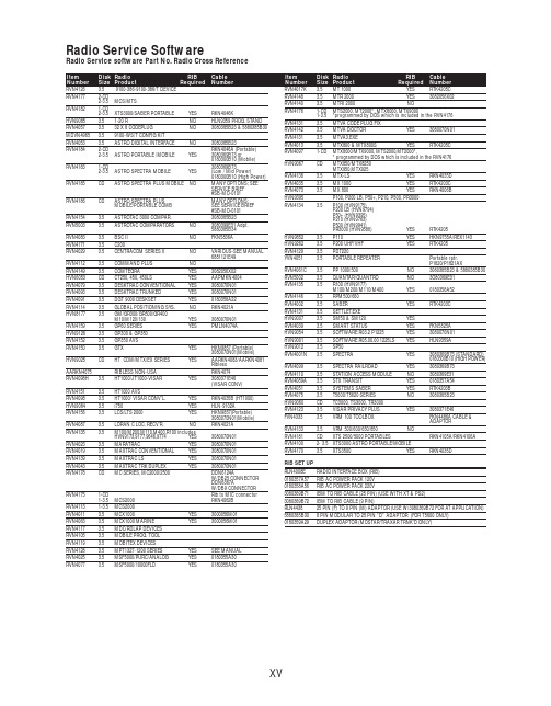
RVN4126 3.59100-386-9100-386/T DEVICERVN41772-CD2-3.5MCS/MTSRVN41821-CD2-3.5XTS3000/SABER PORTABLE YES RKN4046KHVN9085 3.51-20 R NO HLN9359 PROG. STAND RVN4057 3.532 X 8 CODEPLUG NO3080385B23 & 5880385B30 MDVN4965 3.59100-WS/T CONFIG KITRVN4053 3.5ASTRO DIGITAL INTERFACE NO3080385B23RVN41842-CD RKN4046A (Portable) 2-3.5ASTRO PORTABLE /MOBILE YES3080369B73 or0180300B10 (Mobile) RVN41831-CD3080369B732-3.5ASTRO SPECTRA MOBILE YES(Low / Mid Power)0180300B10 (High Power) RVN4185CD ASTRO SPECTRA PLUS MOBILE NO MANY OPTIONS; SEESERVICE BRIEF#SB-MO-0101RVN4186CD ASTRO SPECTRA PLUS MANY OPTIONS;MOBILE/PORTABLE COMB SEE SERVICE BRIEF#SB-MO-0101RVN4154 3.5ASTROTAC 3000 COMPAR.3080385B23RVN5003 3.5ASTROTAC COMPARATORS NO3080399E31 Adpt.5880385B34RVN4083 3.5BSC II NO FKN5836ARVN4171 3.5C200RVN4029 3.5CENTRACOM SERIES II NO VARIOUS-SEE MANUAL6881121E49RVN4112 3.5COMMAND PLUS NORVN4149 3.5COMTEGRA YES3082056X02HVN6053CD CT250, 450, 450LS YES AAPMKN4004RVN4079 3.5DESKTRAC CONVENTIONAL YES3080070N01RVN4093 3.5DESKTRAC TRUNKED YES3080070N01RVN4091 3.5DGT 9000 DESKSET YES0180358A22RVN4114 3.5GLOBAL POSITIONING SYS.NO RKN4021AHVN8177 3.5GM/GR300/GR500/GR400M10/M120/130YES3080070N01RVN4159 3.5GP60 SERIES YES PMLN4074AHVN9128 3.5GP300 & GP350RVN4152 3.5GP350 AVSRVN4150 3.5GTX YES HKN9857 (Portable)3080070N01(Mobile) HVN9025CD HT CDM/MTX/EX SERIES YES AARKN4083/AARKN4081RiblessAARKN4075RIBLESS NON-USA RKN4074RVN4098H 3.5HT1000/JT1000-VISAR YES3080371E46(VISAR CONV)RVN4151 3.5HT1000 AVSRVN4098 3.5HT1000/ VISAR CONV’L.YES RKN4035B (HT1000) HVN9084 3.5i750YES HLN-9102ARVN4156 3.5LCS/LTS 2000YES HKN9857(Portable)3080070N01(Mobile) RVN4087 3.5LORAN C LOC. RECV’R.NO RKN4021ARVN4135 3.5M100/M200,M110,M400,R100 includesHVN9173,9177,9646,9774YES3080070N01RVN4023 3.5MARATRAC YES3080070N01RVN4019 3.5MAXTRAC CONVENTIONAL YES3080070N01RVN4139 3.5MAXTRAC LS YES3080070N01RVN4043 3.5MAXTRAC TRK DUPLEX YES3080070N01RVN4178CD MC SERIES, MC2000/2500DDN6124AW/DB25 CONNECTORDDN6367AW/DB9 CONNECTOR RVN41751-CD Rib to MIC connector 1-3.5MCS2000 RKN4062BRVN41131-3.5MCS2000RVN4011 3.5MCX1000YES3000056M01RVN4063 3.5MCX1000 MARINE YES3000056M01RVN4117 3.5MDC/RDLAP DEVICESRVN4105 3.5MOBILE PROG. TOOLRVN4119 3.5MOBITEX DEVICESRVN4128 3.5MPT1327-1200 SERIES YES SEE MANUALRVN4025 3.5MSF5000/PURC/ANALOG YES0180355A30RVN4077 3.5MSF5000/10000FLD YES0180355A30RVN4017K 3.5MT 1000YES RTK4205CRVN4148 3.5MTR 2000YES3082056X02RVN4140 3.5MTRI 2000NORVN41761-CD MTS2000, MT2000*, MTX8000, MTX90001-3.5*programmed by DOS which is included in the RVN4176RVN4131 3.5MTVA CODE PLUG FIXRVN4142 3.5MTVA DOCTOR YES3080070N01RVN4131 3.5MTVA3.EXERVN4013 3.5MTX800 & MTX800S YES RTK4205CRVN4097 1-CD MTX8000/MTX9000,MTS2000,MT2000*,* programmed by DOS which is included in the RVN4176HVN9067CD MTX850/MTX8250MTX950,MTX925RVN4138 3.5MTX-LS YES RKN4035DRVN4035 3.5MX 1000YES RTK4203CRVN4073 3.5MX 800YES RKN4006BHVN9395 P100, P200 LB, P50+, P210, P500, PR3000RVN4134 3.5P100 (HVN9175)P200 LB (HVN9794)P50+ (HVN9395)P210 (HVN9763)P500 (HVN9941)PR3000 (HVN9586)YES RTK4205HVN9852 3.5P110YES HKN9755A/REX1143 HVN9262 3.5P200 UHF/VHF YES RTK4205RVN4129 3.5PDT220YVN4051 3.5PORTABLE REPEATER Portable rptr.P1820/P1821AXRVN4061C 3.5PP 1000/500NO3080385B23 & 5880385B30 RVN5002 3.5QUANTAR/QUANTRO NO3O80369E31RVN4135 3.5R100 (HVN9177)M100/M200/M110/M400YES0180358A52RVN4146 3.5RPM500/660RVN4002 3.5SABER YES RTK4203CRVN4131 3.5SETTLET.EXEHVN9007 3.5SM50 & SM120YESRVN4039 3.5SMART STATUS YES FKN5825AHVN9054 3.5SOFTWARE R03.2 P1225YES3080070N01HVN9001 3.5SOFTWARE R05.00.00 1225LS YES HLN9359AHVN9012 3.5SP50RVN4001N 3.5SPECTRA YES3080369B73 (STANDARD)0180300B10 (HIGH POWER) RVN4099 3.5SPECTRA RAILROAD YES3080369B73RVN4110 3.5STATION ACCESS MODULE NO3080369E31RVN4089A 3.5STX TRANSIT YES0180357A54RVN4051 3.5SYSTEMS SABER YES RTK4203BRVN4075 3.5T5600/T5620 SERIES NO3080385B23HVN9060CD TC3000, TS3000, TR3000RVN4123 3.5VISAR PRIVACY PLUS YES3080371E46FVN4333 3.5VRM 100 TOOLBOX FKN4486A CABLE &ADAPTORRVN4133 3.5VRM 500/600/650/850NORVN4181CD XTS 2500/5000 PORTABLES RKN4105A/RKN4106A RVN41002- 3.5XTS3000 ASTRO PORTABLE/MOBILERVN4170 3.5XTS3500YES RKN4035DRIB SET UPRLN4008E RADIO INTERFACE BOX (RIB)0180357A57RIB AC POWER PACK 120V0180358A56RIB AC POWER PACK 220V3080369B71IBM TO RIB CABLE (25 PIN) (USE WITH XT & PS2)3080369B72IBM TO RIB CABLE (9 PIN)RLN443825 PIN (F) TO 9 PIN (M) ADAPTOR (USE W/3080369B72 FOR AT APPLICATION) 5880385B308 PIN MODULAR TO 25 PIN ”D” ADAPTOR (FOR T5600 ONLY)0180359A29DUPLEX ADAPTOR (MOSTAR/TRAXAR TRNK’D ONLY)Item Disk Radio RIB Cable Number Size Product Required Number Item Disk Radio RIB Cable Number Size Product Required NumberUtilizing your personal computer, Radio Service Software (RSS)/Customer Programming Software (CPS)/CustomerConfiguration Software (CCS) enables you to add or reprogram features/parameters as your requirements change. RSS/CPS/CCS is compatible with IBM XT, AT, PS/2 models 30, 50, 60 and 80.Requires 640K RAM. DOS 3.1 or later. Consult the RSS users guide for the computer configuration and DOS requirements. (ForHT1000, MT/MTS2000, MTX838/8000/9000, Visar and some newer products —IBM model 386, 4 MEG RAM and DOS 5.0 or higher are recommended.) A Radio Interface Box (RIB) may be required as well as the appropriate cables. The RIB and cables must be ordered separately.Licensing:A license is required before a software (RVN) order is placed. The software license is site specific (customer number and ultimate destination tag). All sites/locations must purchase their own software.Be sure to place subsequent orders using the original customer number and ship-to-tag or other licensed sites; ordering software without a licensed customer number and ultimate tag may result in unnecessary delays. To obtain a no charge license agreement kit, order RPX4719. To place an order in the U.S. call 1-800-422-4210. Outside the U.S., FAX 847-576-3023.Subscription Program:The purchase of Radio ServiceSoftware/Customer Programming/Customer ConfigurationSoftware (RVN & HVN kits) entitles the buyer/subscriber to three years of free upgrades. At the end of these three years, the sub-scriber must purchase the same Radio Service Software kit to receive an additional three years of free upgrades. If the sub-scriber does not elect to purchase the same Radio Service Software kit, no upgrades will be sent. Annually a subscription status report is mailed to inform subscribers of the RSS/CPS/CCS items on our database and their expiration dates.Notes:1)A subscription service is offered on “RVN”-Radio Service Software/Customer Programming/Customer Configuration Software kits only.2)“RVN” software must only be procured through Radio Products and Services Division (RPSD). Software not procured through the RPSD will not be recorded on the subscription database; upgrades will not be mailed.3)Upgrades are mailed to the original buyer (customer number & ultimate tag).4)SP software is available through the radio product groups.The Motorola General Radio Service Software Agreement is now available on Motorola Online. If you need assistance please feel free to submit a “Contact Us” or call 800-422-4210.SMART RIB SET UPRLN1015D SMART RIB0180302E27 AC POWER PACK 120V 2580373E86 AC POWER PACK 220V3080390B49SMARTRIB CABLE (9 PIN (F) TO 9 PIN (M) (USE WITH AT)3080390B48SMARTRIB CABLE (25 PIN (F) TO 9 PIN (M) (USE WITH XT)RLN4488ASMART RIB BATTERY PACKWIRELESS DATA GROUP PRODUTS SOFTWARERVN4126 3.59100-386/9100T DEVICES MDVN4965 3.59100-WS/T CONFIG’TN RVN41173.5MDC/RDLAP DEVICESPAGING PRODUCTS MANUALS6881011B54 3.5ADVISOR6881029B90 3.5ADVISOR ELITE 6881023B20 3.5ADVISOR GOLD 6881020B35 3.5ADVISOR PRO FLX 6881032B30 3.5BR8506881032B30 3.5LS3506881032B30 3.5LS5506881032B30 3.5LS7506881033B10 3.5LS9506881035B20 3.5MINITOR III8262947A15 3.5PAGEWRITER 20008262947A15 3.5PAGEWRITER 2000X 6881028B10 3.5TALKABOUT T3406881029B35 3.5TIMEPORT P7308262947A15 3.5TIMEPORT P930NLN3548BUNIVERSAL INTERFACE KITItem Disk Radio NumberSize Product。
Bussmann

Finger-safe power distribution blocksCatalog symbol:• PDBFS_Description:The small footprint, high Short-Circuit Current (SCCR) Bussmann™ series power distribution blocks provide IP20* finger-safe protection under specified conditions. These UL® Listed, single-pole blocks are of a modular design that permits dovetailing together the required number of poles for an application and still meet the UL 1953 minimum 1” and 2” spacing required per UL 508A for feeder circuit applications and per NEC® for field installations.With SCCRs up to 200 kA, these blocks help achieve compliance with National Electrical Code (NEC) and OSHA requirements by resolving a common SCCR “weak link” in industrial control panels.To increase application flexibility, these blocks feature dual-wire rated ports that accept copper or aluminum conductors while retaining a UL Listed status.With panel or 35 mm DIN-Rail** mounting for application flexibility these blocks are suitable for installation in wireways and industrial control panel feeder and branch circuits.* See table on page 5.** PDFFS504 panel mount only.Catalog number example:PDBFS204 is a 1-pole blockWhere:• The catalog symbol “PDBFS” defines the block as a finger-safe design.• The catalog number ending “204” in this example defines this block’s lineside and loadside characteristics covering the ampacity, number of ports and wire sizes, etc.• See the catalog number table for details on the available lineside/loadside characteristics.How to order:From the catalog number table, select the catalog number that defines the desired lineside/loadside port and conductor characteristics.Order one block per pole for the application. Multiple single-pole blocks can be ganged together via the dovetailing feature to form multi-pole configurations.Specifications:Ratings• Volts:• 600 V (UL)• 690 V (IEC)• Amps: 175 to 760 A• SCCR: Up to 200 kA (see table for circuit protection details)Agency information• UL 1953 Listed, Guide QPQS, File E256146• CSA® Certified, Class 6228-01, File 47235• RoHS compliant• CEFlammability rating• UL 94 V0Storage and operating temperature range • -4°F to 248°F (-20°C to 120°C)Conductors†• Stranded 75°C copper and aluminum• Higher temperature rated conductors permitted with appropriate derating† As specified in the catalog number table.2Technical Data 10536Effective June 2021Finger-safe power distribution blocks/bussmannseriesFeatures and benefits•IP20 finger-safe under specified conditions increases safety by isolating energized connections.•Wire-ready captive termination screws cannot be misplaced and are shipped “backed out” to save time on conductor installation.• Sliding DIN-Rail latch provides easy block mounting.•For multiple pole applications, all single-pole units can be gang mounted by using the interlocking dovetail pins that are pre-installed on the side of the blocks.•Elongated panel-mounting holes provide greater flexibility and installation ease when matching up with drilled panel holes.Dual wire port application•Rated for dual wire port application to increase the possiblenumber of lineside and loadside connections. E.g., PDBFS220 can accept two wires into the lineside port (#4 - #14 Cu, #4 - #8 Al) and two wires per port (eight connections total) on the loadside lug (#8 - #14 Cu, #8 Al).•Dual wire applications are only viable when using two wires of the same size, stranding, and insulating and conductor material.Ferrule terminal application•Bussmann series PDBFS power distribution blocks are rated for use with UL Listed ferrules (see catalog number table for details).•Ferrule applications allow for the use of a broader range of conductor stranding and simulate a more efficient, solid wire connection with the PDBFS terminal port.•Always use UL Listed ferrules in accordance with the manufacturer’s specifications and instructions.Catalog numbers:(customer supplied) applied according to the manufacturer’s specifications. Ferrule ratings apply to copper wire only.** See pages 4 and 5 for the tested upstream overcurrent protective devices necessary for achieving these SCCRs.† Torque rating for dual wire and ferrule application is 30.5 N•m (270 Lb-in).†† Torque rating for ferrule application is 13.6 N•m (120 Lb-in).3Finger-safe power distribution blocksTechnical Data 10536Effective June 2021/bussmannseries Selecting SCCR power distribution blocks and terminal blocksShort-circuit current rated power distribution blocksBussmann series power distribution blocks have three distinct styles to match different application needs. There are the PDBFS_ and PDB_ high short-circuit current rated power distribution blocks and the 16_ power terminal blocks. The differences are whether the power distribution blocks are enclosed or not, and whether they are UL 1953 Listed power distribution blocks or UL 1059 Recognized power terminal blocks, which have different minimum spacing requirements. The table on this page will assist you in selecting which block is right for your application.Why these are importantPer the NEC and OSHA, equipment cannot be installed in anelectrical system at a location where the available fault (short-circuit) current is greater than the equipment’s SCCR.Further, equipment SCCRs are required in the 2014 NEC and for UL 508A Listed control panels. Marking the equipment SCCR on control panels (NEC 409.110), industrial machinery electrical panelsSelection tableThis table provides an overview of the three Bussmann series power distribution and terminal blocks mentioned above. For details on the PDB_ blocks, see data sheet number 10537. For the 16_ blocks, see data sheet numbers 10533 (UL Recognized power distribution blocks),10534 (splicer blocks) and 10535 (stud blocks).PDBFS_distribution blocksY es***Y es Y es Y es Y es Y es Y esPDB_UL 1953 Listed powerdistribution blocksNo †Y es Y es Y es Y es Y es Y es, with optional cover 16_UL 1059 Recognizedterminal blocksNo †Y esNo ††Y esNo ††Y esNo* When protected by proper fuse class with maximum ampere rating specified or smaller.** For details, see PDB and TB minimum spacing requirements for equipment table below.*** IP20 finger-safe under specific conditions, see data sheet page 5.† Optional covers are available. Not IP20, but provide a safety benefit.††No, except: Y es, if single pole units installed with proper spacings.Power distribution and terminal block minimum spacing requirements for equipment508A branch circuits 3/8”1/2”1/2”1995 HVAC3/8”1/2”1/2”Note: Refer to specific UL standards for complete spacing details.(NEC 670.3(A)), and HVAC equipment (NEC 440.4(B)) is required by the NEC.Power distribution and terminal blocks not marked with a component SCCR are typically one of the weakest links in a control panel’s equipment SCCR and may limit the equipment SCCR to no more than 10 kA. The PDBFS_ and PDB_ products have the increased spacing required for use in feeder circuits of equipment listed to UL 508A (UL 1059 terminal blocks must be evaluated for proper spacings). Also, for building wiring systems, the PDBFS_ andPDB_ power distribution blocks can be used to meet the 2014 NEC requirements in section 376.56(B) for power distribution blocks in wireways.See the last page of this data sheet for SCCR tools and resources to help you further understand and solve your SCCR needs.4Technical Data 10536Effective June 2021Finger-safe power distribution blocks/bussmannseriesUpstream fusing for SCCR and minimum enclosure dataThis table contains the tested SCCR levels for each PDBFS power distribution block using the specified lineside and loadside conductors and Bussmann series Class J, RK1, RK5 and T fuses. Using these tested SCCR levels also requires the power distribution block be installed in anenclosure with the minimum size indicated for each catalog number.PDBFS2202/0 - #8#4 - #1220010060200200 kA 16 x 16 x 6.75#4 - #1417510030175100 kA 2001006020050 kA PDBFS303350 - #6350 - #6400200100400200 kA 36 x 30 x 12.625PDBFS330500 - #6#2 - #6400200100400200 kA 24 x 20 x 6.75#6 - #142001006020050 kA 17510030175100 kA PDBFS377300 - #4#4600400200600200 kA 24 x 20 x 6.75400200100400100 kA #4 - #142001006020050 kA #4#460040020060050 kA PDBFS500350350600400200600200 kA 36 x 30 x 12.625350 - #4350 - #4600400200600100 kA PDBFS504500500600600200800**200 kA 36 x 30 x 12.625500 - #6500 - #6600400200600100 kAAmpacities 75°C per NEC ® Table 310.16 and UL 508A Table 28.1.* Class G 60 A (SC-60) or less or Class CC 30 A (LP-CC-30, FNQ-R-30, KTK-R-30) or less are suitable for all SCCRs in this table.** Class L 800 A (KRP-C 800_SP) or less fuses suitable for this particular SCCR case.Upstream circuit breakers for SCCR and minimum enclosure dataThis table contains the tested SCCR levels for each PDBFS power distribution block using the specified lineside and loadside conductors and Eaton and General Electric circuit breakers. Using these tested SCCR levels also requires the power distribution block be installed in an enclosure with the minimum size indicated for each catalog number.PDBFS SCCR as rated with Eaton circuit breakersPDBFS2042/0 - #82/0 - #865480E125H, EGB125, E125B, EGE125,E125G, EGS125, E125S, PDG13P , PDG13M12516 x 16 x 6.75PDBFS330500 - #3#2 - #814480LGH400, L400H, LGE400, L400E, LGS400, L400S, PDG33M, PDG33G, PDG33K 40024 x 20 x 6.7525LGC400, L400C, LGU400,L400U, LGX400, L400X, PDG33P PDBFS377(2) 300 - #2#430480LGH600, L600H, LGE600, L600E, LGS600, L600S, PDG33M, PDG33G, PDG33K60024 x 20 x 6.75#618#814#442LGC600, L600C, LGU600,L600U, LGX600, L600X, PDG33P#635#8145Finger-safe power distribution blocksTechnical Data 10536Effective June 2021/bussmannseriesPDBFS SCCR as rated with General Electric circuit breakersPDBFS2042/0 - #82/0 - #848016 x 16 x 6.7525SEHA, PEAC, PEBC,PEAE, PEBE150PDBFS2202/0 - #8#4 - #1265480SELA, PEAN, PEBN 15016 x 16 x 6.7525SEHA, PEAC, PEBC,PEAE, PEBE150PDBFS303250 - #6350 - #665480SFLA, PEDN, PEEN 25024 x 20 x 6.75250 - #635SFHA, PEDE, PEEE 2503/0 - #6350 - #665SELA, PEAN, PEBN 15025SEHA, PEAC, PEBC,PEAE, PEBE150PDBFS330250 - #6#2 - #1265480SFLA, PEDN, PEEN 25024 x 20 x 6.7535SFHA, PEDE, PEEE 2503/0 - #665SELA, PEAN, PEBN 15025SEHA, PEAC, PEBC,PEAE, PEBE150Specified installation conditions for IP20 finger-safe ratingsThis table contains the installed wire and trim lengths, and other conditions the PDBFS power distribution blocks need in order to be compliant withIP20 specifications. IP20 compliance status is indicated in the lineside and loadside wire port and terminal screw opening columns.PDBFS2202/0 - #80.75 (19)Y es Y es #4 - #14Top row 0.55 (14), Bottom row 0.85 (22)Y es Y es Screws fully opened N/A Y es No wire in hole No N/A PDBFS303350kcmil - 2/01.35 (34)Y es Y es 350kcmil - 2/01.25 (32)Y es Y es 1/0 - #6No Y es 1/0 - #6No Y es PDBFS330500 - 250kcmil1.25 (32)Y esY es #2 - #14Top row 0.59 (15), Bottom row 1.2 (30)Y es Y es 4/0 - #6No Y es Screws fully opened N/A Y es No wire in hole Y es N/A PDBFS377300kcmil - 4/0Top row 1.15 (29)bottom row 1.4 (36)Y esY es #4 - #14Top row 0.55 (14), Middle row 1.00 (35), Bottom row 1.22 (31)Y es Y es 3/0 - #4No Y es Screws fully open N/A Y es Screws fully open N/A No No wire in port Y es N/A No wire in port No N/A PDBFS500350kcmil - 2/01.25 (32)NoY es 350kcmil - 2/01.25 (32)Y esY es 1/0 - #4No Y es 1/0 - #4No Y es Screws fully opened N/A No Screws fully open N/A No No wire in port No N/A No wire in port No N/A PDBFS504500 - 350kcmil 1.25 (32)Y esY es 500 - 350kcmil 1.25 (32)Y esY es 300 - #6No Y es 300 - #6No Y es Screws fully open N/A No Screws fully opened N/A No No wire in portNoN/ANo wire in portNoN/A6Technical Data 10536Effective June 2021Finger-safe power distribution blocks/bussmannseriesDimensions — in (mm)PDBFS2201.03 (26) 3.73 (95) 2.15 (54) 3.55 (90) 2.92 (74)0.20 (5)0.40 (10)N/A PDBFS3031.54 (39) 4.66 (118) 2.87 (73) 4.49 (114) 3.82 (97)0.20 (5)0.44 (11)N/A PDBFS3301.54 (39) 4.66 (118) 2.87 (73) 4.49 (114) 3.82 (97)0.20 (5)0.44 (11)N/A PDBFS3771.88 (47) 4.66 (118) 2.93 (74) 4.49 (114) 3.82 (97)0.20 (5)0.44 (11)N/A PDBFS500 2.37 (60) 4.66 (118) 2.60 (66) 4.49 (114) 3.82 (97)0.20 (5)0.44 (11)N/APDBFS5042.54 (64)4.49 (114)3.15 (80)—3.82 (97)0.20 (5)0.35 (9)1.81 (46)LinesideLoadsideLinesideLoadsidePDBFS220PDBFS204PDBFS303PDBFS3307Finger-safe power distribution blocksTechnical Data 10536Effective June 2021/bussmannseries LinesideLoadsideLinesideLoadsideLinesideLoadsidePDBFS377PDBFS500PDBFS504Multi-pole block gangingPDBFS power distribution blocks are single-pole devices that can be ganged for the required number of poles using the interlocking dovetail pins that are pre-installed on each block.To interlock and gang two or more blocks (DIN-Rail or panel mount):•Place blocks of the same catalog number side-by-side and slide the dovetail pin of one block into the reciprocal slot on the other and press together until fully seated and the backs of both blocks are coplanar.•Repeat the step above until the number of desired poles are gangedNote: Dissimilar PDBFS blocks can be ganged together. E.g., a PDBFS204 can be ganged with a PDBFS220 using the interlocking dovetailing pins. Ganging a PDBFS504 with any other PDBFS will prevent DIN-Rail mounting.Dovetailing feature permits easy ganging for multi-pole applications8Finger-safe power distribution blocksTechnical Data 10536Effective June 2021Eaton, Bussmann and OSCAR are valuable trademarks of Eaton in the U.S. and other countries. Y ou are not permitted to use the Eaton trademarks without prior written con-sent of Eaton.CSA is a registered trademark of the Canadian Standards Group.NEC is a registered trademark of the National Fire Protection Association, Inc.UL is a registered trademark of the Underwriters Laboratories, Inc.Eaton1000 Eaton Boulevard Cleveland, OH Bussmann Division 114 Old State Road Ellisville, MO 63021United States/bussmannseries © 2021 EatonAll Rights Reserved Publication No. 10536June 2021Follow us on social media to get thelatest product and support information.For Eaton’s Bussmann series product information,call 1-855-287-7626 or visit:/bussmannseriesThe only controlled copy of this data sheet is the electronic read-only version located on the Eaton network drive. All other copies of this document are by definition uncontrolled. This bulletin is intended to clearly present comprehensive product data and provide technical information that will help the end user with design applications. Eaton reserves the right, without notice, to change design or construction of any products and to discontinue or limit distribution of any products. Eaton also reserves the right to change or update, without notice, any technical information contained in this bulletin. Once a product has been selected, it should be tested by the user in all possible applications.DIN-Rail mountingAll versions of the Bussmann series PDBFS power distribution blocks can be DIN-Rail mounted except for the PDBFS504, which can only be panel mounted.It is recommended for multi-pole applications that the individual blocks be ganged using the included dovetailing feature. See Multi-pole block ganging for details.To mount, perform the following:•Using an appropriate size flat blade screw driver, open the DIN-Rail latch that is on the lineside of each block.•Hook the loadside DIN-Rail tabs onto the lower edge of the 35 mm DIN-Rail•Rotate the block(s) up until they are seated over the upper and lower edges of the DIN-Rail•Push the DIN-Rail latch(es) down and into the locked position.To remove blocks, reverse the previous steps.Note: To prevent damage to the block housing when torquing the terminal screws, DIN-Rail end stops are required on each side of the block or ganged blocks.The recommended Bussmann series DIN-Rail end stops are:BRKT-NDSCRW2DIN-Rail end stop with screw-clamp anchorPanel mountingAll Bussmann series PDBFS power distribution blocks can be panel mounted. It is recommended for multi-pole applications that the individual blocks be ganged using the included dovetailing feature. See Multi-pole block ganging for details.Use two (2) suitable length #10 or M5 screws for each block being mounted. Use four (4) screws for each PDBFS504 block. The max torque for the mounting screws is 17 in-lbs (1.92 N •m).SCCR tools and resourcesEaton offers many resources that help customers understand and assess their SCCR needs.Please use the following whenever you have questions, concerns or just need help with SCCR ratings.Engineering services for SCCROSCAR™ compliance software eliminates the guesswork in equipment SCCR calculations.This innovative OSCAR compliance software assists customer compliance with new Code and standards requirements for short-circuit current ratings as they relate to control panels, equipment and assemblies. Go to and request a seven-day free trial.If your equipment SCCR needs improvement, contact the Bussmann Application Engineers for a free design review. Call toll-free1-855-BUSSMANN (855-287-7626) or email FuseT *************.Online SCCR tools and publications•Free SCCR Protection Suite online tool. An easy, fast way to search for components and their SCCRs. Visit .•Application notes:• Developing an effective SCCR plan for facilities and purchasers of industrial equipment — publication no. 10367•Developing an equipment SCCR standard for manufacturers of industrial equipment — publication no. 10368•Four steps to determine equipment SCCR — publication no. 10538• Equipment SCCR made easy brochure — publication no. 10374•SPD (Selecting Protective Devices) handbook; over 250 pages covering the application of overcurrent protective devices, SCCR and more — publication no. 3002。
TE Connectivity Universal MATE-N-LOK 产品规格说明书
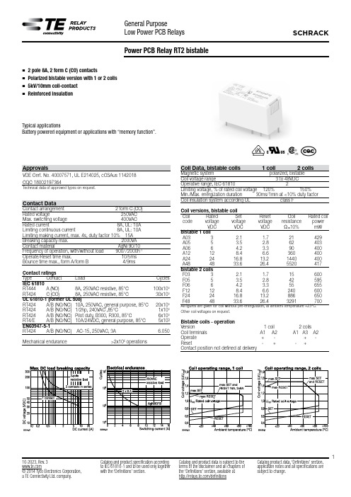
110-2023, Rev. 3© 2014 Tyco Electronics Corporation,a TE Connectivity Ltd. company.Catalog and product specification according to IEC 61810-1 and to be used only together with the ‘Definitions’ section.Catalog and product data is subject to the terms of the disclaimer and all chapters of the ‘Definitions’ section, available at /definitionsCatalog product data, ‘Definitions’ section, application notes and all specifications aresubject to change.n2 pole 8A, 2 form C (CO) contactsn Polarized bistable version with 1 or 2 coils n 5kV/10mm coil-contactnReinforced insulationTypical applicationsBattery powered equipment or applications with “memory function”.ApprovalsVDE Cert. No. 40007571, UL E214025, cCSAus 1142018 CQC 180********Technical data of approved types on request.Contact DataContact arrangement 2 form C (CO)Rated voltage 250VAC Max. switching voltage 400VAC Rated current 8A, UL: 10A Limiting continuous current 8A, UL: 10A Limiting making current, max. 4s, duty factor 10% 15A Breaking capacity max. 2000VA Contact material AgNi 90/10Frequency of operation, with/without load 900/72000h -1Operate/Reset time max. 10/5ms Bounce time max., form A/form B 4/9msContact ratings Type Contact Load Cycles IEC 61810RT444 A (NO) 8A, 250VAC resistive, 85°C 100x103 RT424 C (CO) 8A, 250VAC resistive, 85°C 30x103UL 61810-1 (former UL 508)RT424 A/B (NO/NC) 10A, 250VAC, general purpose, 85°C 20x103 RT424 A/B (NO/NC) 1/2hp, 240VAC ,85°C 1x10³ RT424 A/B (NO/NC) Pilot duty, B300, R300, 85°C 6x10³ RT4/E A/B (NO/NC) 10A/24VDC, general purpose, 85°C 5x10³EN60947-5-1RT424 A/B (NO/NC) AC-15, 250VAC, 3A 6.050Mechanical endurance >2x10⁶ operationsPower PCB Relay RT2 bistableZ b210-2023, Rev. 3© 2014 Tyco Electronics Corporation,a TE Connectivity Ltd. company.Catalog and product specification accordingto IEC 61810-1 and to be used only togetherwith the ‘Definitions’ section.Catalog and product data is subject to theterms of the disclaimer and all chapters ofthe ‘Definitions’ section, available at/definitionsCatalog product data, ‘Definitions’ section,application notes and all specifications aresubject to change.Product code Version Contacts ContactmaterialCoil version Coil Part numberRT424A058A, 2 form C (CO)AgNi 90/10Bistable 1coil5VDC4-1393243-4RT424A12pinning 5mm,contacts12VDC4-1393243-6RT424F05flux proof Bistable 2 coils5VDC5-1393243-2RT424F1212VDC5-1393243-4RT424F2424VDC5-1393243-6RT424F4848VDC5-1393243-7 RTE24F248A 24VDC8-1415541-7 RTE24F06pinning 5mm6VDC1-1415020-1 RTE24F12wash tight12VDC7-1415072-1Power PCB Relay RT2 bistable (Continued)Other Data (continued)Terminal type PCB-THT, plug-in1)Weight 13gResistance to soldering heat THTIEC 60068-2-20 270°C/10sPackaging/unit tube/20 pcs., box/500 pcs.1) socket available for 1 coil version only, see Accessories.AccessoriesFor 1 coil version,details see datasheet A ccessories Industrial Power Relay RTNOTE: indicated contact ratings and electrical endurance data for directwiring of relays (according IEC 61810-1); for relays mounted on socketsderatings may apply.Insulation DataInitial dielectric strengthbetween open contacts 1000Vrmsbetween contact and coil 5000Vrmsbetween adjacent contacts 2500VrmsClearance/creepagebetween contact and coil ≥10/10mmbetween adjacent contacts ≥ 3/4mmMaterial group of insulation parts IIIaTracking index of relay base PTI 250VOther DataMaterial compliance: EU RoHS/ELV, China RoHS, REACH, Halogen contentrefer to the Product Compliance Support Center at/customersupport/rohssupportcenterAmbient temperaturebistable 1 coil -10 to 85°Cbistable 2 coils -40 to 85°CCategory of environmental protectionIEC 61810 RTII - flux proofRTIII - wash tigthVibration/shock resistance (functional),opening B contact 3/5gopening closed A contact 6/15gShock resistance (destructive) 100gPCB layout / terminal assignmentBottom view on solder pins8 A,2 form C (CO) contactsm m to 2.54 m m cana)Dimensionsa) Indicated contactposition while or after coilenergization with resetvoltage.b) for 2 coil version onlyProduct code structure Typical product code RT 4 2 4 F24TypeRT Power PCB Relay RT2 bistableVersion4 8A, pinning 5mm, flux proof E8A, pinning 5mm, wash tightContact configuration2 2 form C (CO) contactsContact material4 AgNi 90/10CoilCoil code: please refer to coil versions tableThis list represents the most common types and does not show all variants covered by this datasheet. Other types on requestOther types on request.。
HOLLiAS-LEC G3 产品一览表
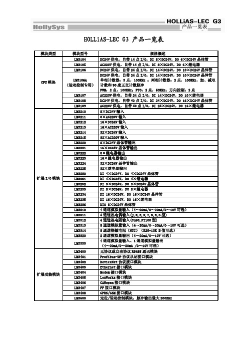
HOLLiAS-LEC G3 产品一览表模块类型 模块型号 规格概述LM3104 DC24V供电,自带14点I/O,DI 8×DC24V,DO 6×DC24V晶体管LM3105 AC220V供电,自带14点I/O,DI 8×DC24V,DO 6×继电器LM3106 DC24V供电,自带24点I/O,DI 14×DC24V,DO 10×DC24V晶体管LM3106A(运动控制专用) DC24V供电,自带24点I/O,DI 14×DC24V,DO 10×DC24V晶体管 单相计数器:3点,100KHz ;两相计数器:2点,100KHz,加、减双计数和90度正交计数脉冲PWM:2点,100KHz;PTO:2点,50KHz;方向控制:2点LM3107 AC220V供电,自带24点I/O,DI 14×DC24V,DO 10×继电器LM3108 DC24V供电,自带40点I/O,DI 24×DC24V,DO 16×DC24V晶体管 CPU模块LM3109 AC220V供电,自带40点I/O,DI 24×DC24V,DO 16×继电器LM3210 8×DC24V输入LM3211 8×AC220V输入LM3212 16×DC24V输入LM3213 16×AC220V输入LM3214 32×DC24V输入LM3215 32×AC220V输入LM3220 8×DC24V晶体管输出LM3221 16×DC24V晶体管输出LM3222 8×继电器输出LM3223 16×继电器输出LM3224 32×DC24V晶体管输出LM3225 32×继电器输出LM3230 DI 4×DC24V,DO 4×DC24V晶体管LM3231 DI 4×DC24V,DO 4×继电器LM3232 DI 8×DC24V,DO 8×DC24V晶体管LM3233 DI 8×DC24V,DO 8×继电器LM3234 DI 16×DC24V,DO 16×DC24V晶体管LM3235 DI 16×DC24V,DO 16×继电器LM3236 DIO 8×DC24V晶体管LM3310 4通道模拟量输入(4~20mA/0~20mA/0~10V可选)LM3311 4通道热电偶输入(J,K,E,N,T,B,R,S型)LM3312 4通道热电阻输入(Cu50,PT100型)LM3313 8通道模拟量输入(4~20mA/0~20mA/0~10V可选)LM3314 8通道热敏电阻(NTC)(R25=10K B值可选)LM3320 2通道模拟量输出(4~20mA/0~10V可选)扩展I/O模块LM3330 4通道模拟量输入、1通道模拟量输出 (4~20mA/0~20mA /0~10V可选)LM3400 无协议或自由协议RS485通讯模块LM3401 Profibus-DP协议从站接口模块LM3402 DeviceNet协议接口模块LM3403 Ethernet接口模块LM3404 Modem接口模块LM3405 LonWorks接口模块LM3406 CANopen接口模块LM3407 FF接口模块LM3408 GPRS/GSM接口模块扩展功能模块LM3500 定位/运动控制模块,脉冲输出最大200KHz。
JUMO 紧固定电导性温度传感器系列说明书

Page 1/4Fax:+49 661 6003-607e-mail:Internet: Fax:+44 1279 635262e-mail:Internet: Fax:315-697-5867e-mail:Internet:Screw-in RTD temperature probewith terminal head form J■For temperatures from -50 to +400°C■As single or double RTD temperature probes ■Available with transmitter ■Protection class IP65Screw-in RTD temperature probes are preferentially used for measuring temperatures in liquids and gases. A decisive selection criterion is the reliable sealing feature of this installation type with vacuum and with overpressure. The application areas are, among others, in the air conditioning technology and refrigeration engineering as well as the HVAC, kiln and apparatus engineering sector.The measuring insert is normally fitted with a Pt100 temperature sensor according to DIN EN 60751, Class B in 2-wire circuit; versions with Pt500 or Pt1000 temperature sensors can also be supplied, as well as 3- and 4-wire circuit connections. A transmitter can be optionally integrated into the connection head.Technical DataTerminal headForm J, die-cast aluminum, M 16x1.5; IP65, ambient temperature -40 to +100°C Caution: reduced ambient temperature range when using transmitters,Data Sheet 70.7030Process connection thread, stainless steel 1.4571Protection tube Stainless steel 1.4571, Ø6mm and Ø8mmMeasuring insert Pt100 temperature sensor according to DIN EN 60751, Class B, two-wire circuit Response times t 0.5 = 5 sec, t 0.9 = 14 sec, in water 0.4m/sec, 6mm dia.Transmitter Analog transmitter, output 4 to 20mA, Data sheet 70.7030AccessoriesSheath, Data Sheet 90.9710 (90.9721)Page 2/4Fax:+49 661 6003-607e-mail:*************Internet: Fax:+44 1279 635262e-mail:*************.uk Internet: Fax:315-697-5867e-mail:************Internet:DimensionsType 902030/10Type 902030/11Type 902030/31Type 902030/80Page 3/4Fax:+49 661 6003-607e-mail:*************Internet: Fax:+44 1279 635262e-mail:*************.uk Internet: Fax:315-697-5867e-mail:************Internet:Order details:Screw-in RTD temperature probe with terminal head form J(1)Basic type902030/10Screw-in RTD temperature probes with continuous sheath902030/11Screw-in RTD temperature probes with stepped sheath(with Ø6 to Ø3.8mm; with Ø8 to Ø6mm)902030/31Screw-in RTD temperature probes with stepped sheath for air measurement902030/80Screw-in RTD temperature probes with spring-loaded connection,12mm spring deflection,connection head rotatable by 360°(2)Operating temperature in °Cx x647-20 to +150°C (only in conjunction with class B and 1x Pt100/1x Pt1000 in 2-wire circuit)x378-50 to +180°C x x x380-50 to +200°C x x 386-50 to +260°C x x 402-50 to +400°C (3)Measuring insertx x x x 10011x Pt100 in 3-wire-circuit x x x x 10031x Pt100 in 2-wire circuit x x x x 10051x Pt1000 in 2-wire circuit x x x x 10111x Pt100 in 4-wire circuit x x x x20032x Pt100 in 2-wire circuit(4)Tolerance class according to EN 60751x x x x 1Class B (standard)x x x x 2Class A(5)Protection tube diameter D in mm x x x 6Ø6mm (standard)x x 8Ø8mm (6)Fitting length EL in mm (100≤EL ≤1000)x x 5050mm x x x x 100100mm x x x x 150150mm x x x x 250250mm x x x x 300300mmxx xx...Specification in plain text (50mm steps)(7)Process connection x x x 102Screw connection (thread) G 1/4x x x 103Screw connection (thread) G 3/8x x x x 104Screw connection (thread) G 1/2(8)Extra codesx x x x 000without extra codesx x x x3301x analog transmitter, 4 to 20mA 1 output, Data sheet 70.7030(1)(2)(3)(4)(5)(6)(7)(8)Order code ------/Order example902030/10-402-1001-1-6-100-104/0001Specify measuring range in plain text.Page 4/4Fax:+49 661 6003-607e-mail:*************Internet: Fax:+44 1279 635262e-mail:*************.uk Internet: Fax:315-697-5867e-mail:************Internet:Stock versions(1)(2)(3)(4)(5)(6)(7)(8)Part No.902030/10-380-2003-1-6-50-104/00090/00533450902030/10-380-2003-1-6-100-104/00090/00533451902030/10-380-2003-1-6-150-104/00090/00533452902030/10-402-1003-1-6-50-104/00090/00055692902030/10-402-1003-1-6-100-104/00090/00055693902030/10-402-1003-1-6-150-104/00090/00055694902030/10-402-1003-1-6-300-104/00090/00065691902030/10-402-1003-1-6-250-104/00090/00533433902030/10-402-2003-1-6-50-104/00090/00383011902030/10-402-2003-1-6-100-104/00090/00526429902030/10-402-2003-1-6-150-104/00090/00533442902030/10-402-1003-1-6-50-103/00090/00478984902030/10-402-1003-1-6-100-103/00090/00424045902030/10-380-1003-1-6-100-104/330(-40 to +60°C)90/00533453902030/10-647-1003-1-6-100-104/330(0 to 100°C)90/00533454902030/10-647-1003-1-6-150-104/330(0 to 100°C)90/00533468902030/10-402-1005-1-6-100-104/00090/00359611902030/10-402-1005-1-6-150-104/00090/00411610902030/10-647-1003-1-6-50-104/00090/00533448902030/10-647-1003-1-6-100-104/00090/00533449902030/10-647-1003-1-6-150-104/00090/00508957902030/31-380-1003-1-6-75-104/00090/00438406902030/31-380-1003-1-6-100-104/00090/00438408902030/31-380-1003-1-6-150-104/00090/00438409。
- 1、下载文档前请自行甄别文档内容的完整性,平台不提供额外的编辑、内容补充、找答案等附加服务。
- 2、"仅部分预览"的文档,不可在线预览部分如存在完整性等问题,可反馈申请退款(可完整预览的文档不适用该条件!)。
- 3、如文档侵犯您的权益,请联系客服反馈,我们会尽快为您处理(人工客服工作时间:9:00-18:30)。
• The above process aims at removing 70% of suspended solid and
35% of BOD
• In HK, treated water from Stonecutters Island Treatment Plant is
discharged to Victoria Harbour & Discharge points as far as South of Lamma Island via deep under sea-bed pipeworks
Layout of CEPT Plant at Stonecutters Island
Secondary Treatment (e.g. Shatin Sewage Treatment Plant)
Typical Content in Wastewater
• • • • • • •
pH 7.0 BOD 250 – 350 COD 500 – 700 Suspended Solid 250 – 400 Ammonia Nitrogen 30 – 40 Nitrate Nitrogen <1 Total Phosphate 10 – 15 Note: all unit in mg/l (except pH value)
Composition omp; COD
• BOD (Biological Oxygen Demand) is a measure
of the amount of biodegradable organic substances in water. It is expressed as mg of oxygen required by microorganisms to oxidize the organics in a litre of water COD (Chemical Oxygen Demand) is also a measure for characterizing the amount of oxygen required for chemical oxidation of organic matter. There exists standard tests for determining the BOD and COD values for wastewater.
BRE 349 Building Services I
Sewage Treatment
Definition of Sewerage
• Sewerage also refers to Wastewater • Wastewater: Water that has been used. In
•
•
•
urban area it is a mixture of the wastewater from household, offices and industrial effluents. The organic strength of wastewater is measured by BOD & COD Other Chemicals may include ammonia, nitrate and phosphate Numerous Pathogens exist in wastewater as well
• •
Chemically Enhanced Primary Treatment (CEPT)
• In addition to normal primary treatment, • •
•
Chemicals are added into the water to speed up the sedimentation. No Biological reaction takes place in CEPT In HK, there are three CEPT plants, one at Stonecutters Island (one of the largest in term of capacity in the world) and the other at Cyber Port & Disney Land In 2002, CEPT plant at Stonecutters Island have treated 54.5% of total sewage in HK
•
•
Primary Treatment (Screening plus Sedimentation)
• Further on preliminary treatment, primary
treatment allows waste water to have sedimentation via the installation of sedimentation tanks so as to remove more pollutants Usually no chemical or biological reactions will take place during primary treatment In HK, there is only 4 primary treatment facilities located at NT and outlaying island and only treated 0.4% of total sewage in 2002
removal of grit. Solids larger than 6 mm in diameter are removed from the sewage. Primary Treatment - includes screening, removal of grit and a primary sedimentation process. Solid waste and settleable suspended solids are removed from the sewage. Chemically Enhanced Primary Treatment - chemicals are added during the treatment process to enhance the removal of suspended solids and the biochemical oxygen demand. Secondary Treatment - the sewage is purified by means of a biological treatment process after the primary treatment has been completed. The organic matter in the settled sewage is decomposed by micro-organisms in the biological treatment process. Tertiary Treatment – Highest level of treatment consisting of a combination of physical, chemical and biological processes with the objective of removing nutrients and any remaining suspended solids in the sewage.
Source: Drainage Services Department, HKSAR
Preliminary Treatment (Screening)
• In the case of HK, preliminary treatment aims at
removing large particles of 6mm in diameter or above and grit over 0.2 mm in size from the sewage. Neither Biological or Chemical reactions take place in preliminary treatment In HK, there are a total of 24 preliminary treatment facilities, majority of them are located at urban areas in HK inland and Kowloon, and they have treated 28.7% of sewage
• In 2002, HK have treated 923 millions cubic metres of
sewage
Process of Sewage Treatment
• Preliminary Treatment (Screening) - includes screening and • • • •
precipitation dosage and mixed with the sewage inflow in rapid mix chambers environment for floc to form. Aeration is provided to keep the floc in suspension.
• •
Importance of BOD/COD
• The higher the BOD/COD values, the
higher the amount of microorganisms to consume oxygen for growth. If the wastewater is discharged to the river/sea without treatment, it will endanger the ecology cycle in the water and at the same time contaminate the water sources for all living creatures