0875681444;中文规格书,Datasheet资料
744230181;中文规格书,Datasheet资料

2.1 2.0 1.02012-07-172012-07-172010-09-30SStSStSBaSStSBaWürth Elektronik eiSos GmbH & Co. KGEMC & Inductive SolutionsMax-Eyth-Str. 174638 WaldenburgGermanyTel. +49 (0) 79 42 945 - 0A Dimensions: [mm]F Typical Impedance Characteristics:H1: Classification Reflow Profile for SMT components:H2: Classification Reflow ProfilesProfile FeaturePreheat- Temperature Min (T smin ) - Temperature Max (T smax ) - Time (t s ) from (T smin to T smax )Ramp-up rate (T L to T P )Liquidous temperature (T L )Time (t L ) maintained above T L Peak package body temperature (T p )Time within 5°C of actual peak temperature (t p )Ramp-down rate (T P to T L )Time 25°C to peak temperature Pb-Free Assembly 150°C 200°C60-180 seconds 3°C/ second max.217°C60-150 seconds See Table H320-30 seconds 6°C/ second max.8 minutes max.refer to IPC/JEDEC J-STD-020DH3: Package Classification Reflow TemperaturePB-Free Assembly PB-Free Assembly PB-Free Assembly Package Thickness< 1.6 mm 1.6 - 2.5 mm ≥ 2.5 mmVolume mm³<350260°C 260°C 250°CVolume mm³350 - 2000260°C 250°C 245°CVolume mm³>2000260°C 245°C 245°Crefer to IPC/JEDEC J-STD-020DH Soldering Specifications:I Cautions and Warnings:The following conditions apply to all goods within the product series of WE-CNSWof Würth Elektronik eiSos GmbH & Co. KG:General:All recommendations according to the general technical specifications of the data sheet have to be complied with.The disposal and operation of the product within ambient conditions which probably alloy or harm the wire isolation has to be avoided.If the product is potted in customer applications, the potting material might shrink during and after hardening. Accordingly to this the product is exposed to the pressure of the potting material with the effect that the core, wire and termination is possibly damaged by this pressure and so the electrical as well as the mechanical characteristics are endanger to be affected. After the potting material is cured, the core, wire and termination of the product have to be checked if any reduced electrical or mechanical functions or destructions have occurred.The responsibility for the applicability of customer specific products and use in a particular customer design is always within the authority of the customer. All technical specifications for standard products do also apply for customer specific products.Cleaning solvents which are used to clean the application might damage or change the characteristics of the component.Direct mechanical impact to the product shall be prevented as the ferrite material of the core could flake or in the worst case it could break. Product specific:Follow all instructions mentioned in the datasheet, especially:•The soldering profile has to be complied with according to the technical reflow soldering specification, otherwise no warranty will be su-stained.•All products are supposed to be used before the end of the period of 12 months based on the transfer of title, if not a 100% solderability can´t be warranted.•Violation of the technical product specifications such as exceeding the nominal rated current will result in the loss of warranty.1. General Customer ResponsibilitySome goods within the product range of Würth Elektronik eiSos GmbH & Co. KG contain statements regarding general suitability for certain application areas. These statements about suitability are based on our knowledge and experience of typical requirements concerning the are-as, serve as general guidance and cannot be estimated as binding statements about the suitability for a customer application. The responsibi-lity for the applicability and use in a particular customer design is always solely within the authority of the customer. Due to this fact it is up to the customer to evaluate, where appropriate to investigate and decide whether the device with the specific product characteristics described in the product specification is valid and suitable for the respective customer application or not.2. Customer Responsibility related to Specific, in particular Safety-Relevant ApplicationsIt has to be clearly pointed out that the possibility of a malfunction of electronic components or failure before the end of the usual lifetime can-not be completely eliminated in the current state of the art, even if the products are operated within the range of the specifications.In certain customer applications requiring a very high level of safety and especially in customer applications in which the malfunction or failure of an electronic component could endanger human life or health it must be ensured by most advanced technological aid of suitable design of the customer application that no injury or damage is caused to third parties in the event of malfunction or failure of an electronic component.3. Best Care and AttentionAny product-specific notes, warnings and cautions must be strictly observed.4. Customer Support for Product SpecificationsSome products within the product range may contain substances which are subject to restrictions in certain jurisdictions in order to serve spe-cific technical requirements. Necessary information is available on request. In this case the field sales engineer or the internal sales person in charge should be contacted who will be happy to support in this matter.5. Product R&DDue to constant product improvement product specifications may change from time to time. As a standard reporting procedure of the Product Change Notification (PCN) according to the JEDEC-Standard inform about minor and major changes. In case of further queries regarding the PCN, the field sales engineer or the internal sales person in charge should be contacted. The basic responsibility of the customer as per Secti-on 1 and 2 remains unaffected.6. Product Life CycleDue to technical progress and economical evaluation we also reserve the right to discontinue production and delivery of products. As a stan-dard reporting procedure of the Product Termination Notification (PTN) according to the JEDEC-Standard we will inform at an early stage about inevitable product discontinuance. According to this we cannot guarantee that all products within our product range will always be available. Therefore it needs to be verified with the field sales engineer or the internal sales person in charge about the current product availability ex-pectancy before or when the product for application design-in disposal is considered.The approach named above does not apply in the case of individual agreements deviating from the foregoing for customer-specific products.7. Property RightsAll the rights for contractual products produced by Würth Elektronik eiSos GmbH & Co. KG on the basis of ideas, development contracts as well as models or templates that are subject to copyright, patent or commercial protection supplied to the customer will remain with Würth Elektronik eiSos GmbH & Co. KG.8. General Terms and ConditionsUnless otherwise agreed in individual contracts, all orders are subject to the current version of the “General Terms and Conditions of Würth Elektronik eiSos Group”, last version available at .J Important Notes:The following conditions apply to all goods within the product range of Würth Elektronik eiSos GmbH & Co. KG:分销商库存信息: WURTH-ELECTRONICS 744230181。
10408;10409;中文规格书,Datasheet资料
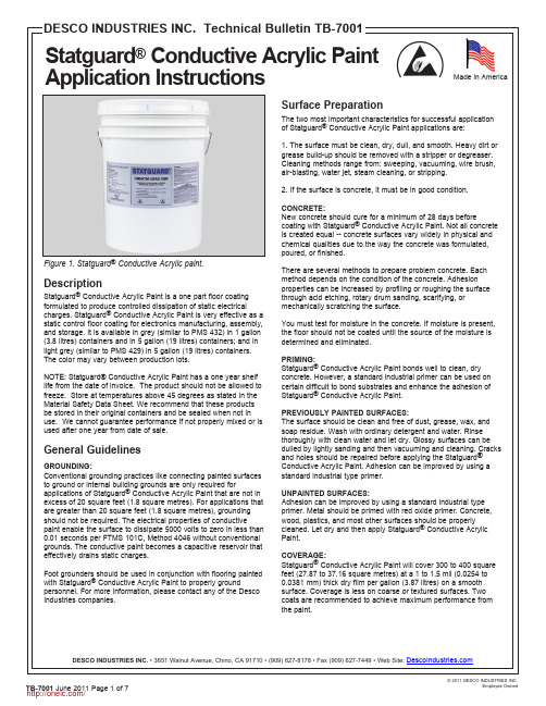
Made in AmericaThe two most important characteristics for successful applicationConductive Acrylic Paint applications are:1. The surface must be clean, dry, dull, and smooth. Heavy dirt or grease build-up should be removed with a stripper or degreaser. Cleaning methods range from: sweeping, vacuuming, wire brush, air-blasting, water jet, steam cleaning, or stripping.2. If the surface is concrete, it must be in good condition.New concrete should cure for a minimum of 28 days beforeConductive Acrylic Paint. Not all concrete is created equal -- concrete surfaces vary widely in physical and chemical qualities due to the way the concrete was formulated,There are several methods to prepare problem concrete. Each method depends on the condition of the concrete. Adhesion properties can be increased by profiling or roughing the surface through acid etching, rotary drum sanding, scarifying, or mechanically scratching the surface.You must test for moisture in the concrete. If moisture is present, the floor should not be coated until the source of the moisture isConductive Acrylic Paint bonds well to clean, dry concrete. However, a standard industrial primer can be used on certain difficult to bond substrates and enhance the adhesion of Conductive Acrylic Paint.PREVIOUSLY PAINTED SURFACES:The surface should be clean and free of dust, grease, wax, and soap residue. Wash with ordinary detergent and water. Rinse thoroughly with clean water and let dry. Glossy surfaces can be dulled by lightly sanding and then vacuuming and cleaning. Cracks and holes should be repaired before applying the Statguard Conductive Acrylic Paint. Adhesion can be improved by using atest area be coated to ensure that the adhesion and electrical of the paint is acceptable. (See Adhesion Testing, Figure 5.) If the 3. Saturate a 1/4” (6.35 mm) fine nap roller or an industrial brush ure must be above 50°F (10°C).Conductive Acrylic Paint is recommended for appropriate static protection.Mix any settled solids to produce a uniform grey color.Saturate a 1/4” fine nap roller with paint, remove excess paint and trapped bine separate cans into a larger A minimum number of strokes from the applicator is recommended.Figure 2. Paint application with roller.Figure 3. Spray paint application Clean UpWash applicators with water immediately after painting. Remove paint spills promptly with a wet cloth. Close container after each use. Keep container from freezing.Drying TimeIt is recommended that Statguard ® Conductive Acrylic Paint be allowed to dry at a temperature in excess of 45°F (7°C) until dry. A minimum of 1 to 2 hours drying time should be allowed before applying the second coat. The finish can be applied after 48-72 hours or until the last coat of paint is cured. Wait a minimum of 12 hours drying time after the last coat before allowing light traffic on the coated area. At high humidity levels, a longer drying time may be necessary. Do not force dry.MaintenanceUse sweeper, vacuum, or broom to remove dirt. Allow two weeks drying time before using a damp mop to clean the coated area. Do not use abrasive cleaners, floor rinse, or scrubbing machine to clean the floor.Finish/SealerDesco Statguard Conductive Acrylic Paint can be overcoated or sealed with Statguard Floor Finish static dissipative coating to increase durability, enhance shine, improve ease of maintenance, and seal out dirt and debris. Desco Statguard ® Conductive Light Grey Acrylic Paint needs the Statguard ® Floor Finish for gloss and ease of maintenance . Statguard ® is a polymer base floor finish/sealer that can be used as a top coat on the Conductive Acrylic Paint. Surface resistivity will then be in the 10E6-10E7 ohms range. Two coats are recommended. Three coats will improve electrical properties, durability and reduce frequency ofLead free, iron oxide, titanium dioxide and extenders 10.27 lbs per gallon (1.0 kilograms per Use a razor to cut into a painted, dried floor.3.Pull the tape off.Apply tape on the precut area.4.Examine the degree of paint separationfrom the concrete.Figure 5. Adhesion test on the painted floor.10E5 ohms/sq. per ASTM D257Static Charge Decay:<0.01 sec. per FTMS 101B, Method 4046Charge Generation:Zero per AATCC Step Test, Method 134-1979RTT:10E5 ohms per ANSI ESD-S7.1RTG:10E5 ohms per ANSI ESD-S7.1TestingTest patch areas should be tested for adhesion and electricalperformance of the paint before applying paint to the entire floor. To best ensure consistent results, the test should be done at various locations.ELECTRICAL PROPERTIES:Test the surface resistivity, point-to-point resistance, and resistance-to-ground properties of coated area per ANSI ESD-S7.1 test method. For quick and easy verification of the paint’s electrical properties, we recommend the use of our a Surface Resistance Test Kit (Figure 4). For more information contact any of the Desco Industries Inc. companies.ADHESION:Allow newly applied paint to dry a minimum of 48 hours before proceeding with the test. At humidity levels over 55% RH, allow 72 hours of drying time before testing. Use a razor to cut a cross or a few perpendicular lines over a 3” by 3” (75 mm by 75 mm) area on several spots of the thoroughly dried area. Use a piece of masking tape to cover the marked area. Make sure the tape is thoroughly adhered to the test area. Pull the tape off the surface and examine the amount of paint which has peeled off during the test. If any significant portion is transferred to the tape, better surface preparation (acid etching, cleaning or sanding) should be done on the substrate to enhance the adhesion.8. EXPOSURE CONTROL/PERSONAL EXPOSUREControl Parameters TLV-value 50 ppm maximum for n-butanol and 25 ppm for Ethylene GlycolMonobutyl EtherOther Regulations NoneMeasures For Technical Control Preferences of technical measure to prevent or control contact with the product.Isolating process and personnel, mechanical ventilation (dilution and localexhaust) and the regulation of process conditions. In case of non-prevention or non-control, a proper protective wearing should be used. Respiratory Protection Not required. Wear MSHA/NIOSH approved respirator where exposure limits areexceeded.Hand Protection Impervious/Neoprene GlovesEye Protection Chemical Splash Goggles (ANSI Z-87.1)Work/Hygienic Practices Wash hands before eating, smoking, or using washroom facilities9. PHYSICAL AND CHEMICAL PROPERTIESForm FluidColor Grey, OpaqueSmell MildpH 8.5Boiling Point at °C >100-101°C (212-214°F)Freezing Point at °C 0.0°C (32.0 °F)Flash Point at °C 65 °CExplosive Limits LEL: 0.8 UEL: 25.0Inflammability Limits N/A(vol.% in air)Solubility in water CompleteVOC per method 24 of EPA 2.3 -2.5 lbs VOC/ galVapor Pressure (mmHg) 92.43 mm @ 20 °CVapor Density (air=1) Heavier than airDensity at 20°C 8.17 lbs./gal or 1.14 g/cm3Specific Gravity (H20=1) 1.21Inflammability Classification according to OSHA and EC-regulations “non-flammable”Ignition Temperature 240.0 °CEvaporation Rate Slower than n-butyl acetate% Volatile by Volume 13.229%10. STABILITY AND REACTIVITYStability/Reactivity Stable product at normal conditionsConditions to avoid Temperatures above 49°C/120°F and below 1°C/34°F, Open flames and sparks. Materials to avoid Strong Oxidizing agents and alkalies.Hazardous Decomposition Oxides of carbon and nitrogen. If involved in fire (from other sources) could conceivably result in release of Carbon Dioxide and Carbon Monoxide fumes.11. TOXICOLOGICAL INFORMATIONIngredient-Material Description PEL TLV (twa) LD50 (mg/kg) LC50 (ppm)mg/m3 ppm (rat) (rbt) (rat)oral dermal inhalEthylene Glycol Monobutyl Ether * 50.0 0.0 25.0 470.0 220.0 0.0Butanol* 50.0 0.0 50.0 0.0 0.0 0.0Mineral Spirits 100.00 0.0 100.0 0.0 0.0 0.02-(2-Butoxyethoxy)ethanol 0.0 0.0 0.0 6560.0 4120.0 0.02-ethyl-1-Hexanol 0.0 0.0 0.0 3730 1970 0.0Ammonium Hydroxide 0.0 35.0 50.0 350.0 0.0 0.0*Listed Chemical Subject To Reporting Requirement of SARA Section 313 of Title III• Acute toxicity• Primary irritant effect:• On the skin: No irritant effect• On the eye: No irritant effect• Sensatization: No sensitizing effects known• Additional toxicological information:The product in not classified according to the calculation method of the General EU Classification guideline for Preparations as issued in the latest version. When used and handled according to specifications, the product does not have any harmful effects to our experience and the information provided to us.12. ECOLOGICAL INFORMATIONGeneral Notes:Water hazard class 1 (German Regulations) (self-assessment): slightly hazardous for water. Do not allow undiluted product or large quantities of it to reach ground water, water course or sewage system.Mobility The product is aqueous and will be separated in aqueous conditions Degradability N/ABioaccumulation Not likelyEcotoxicity None knownReference to BimSchV N/A13. DISPOSAL CONSIDERATIONSProduct Dike and collect material into plastic container. Water rinse and drain, flush smallamounts. Use sanitary landfill d isposal. Follow state and local regulations(RCRA; Subtitle D).Hazardous Waste Number Nonregulated14. TRANSPORT INFORMATIONThis product is not classified for transport under ADR/IMDG regulations.15. REGULATORY INFORMATIONLabeling according To EU guideline: Observe the general safety regulations when handeling chemicals. The product is not subject to identification regulations under EU Directives and the Ordinance on Hazardous Materials (Genman GefStoffV).National Regualtions:Waterhazard class: Water hazard class 1 (Self-assessment): slightly hazard for waterPhysical/Chemical Indication Non-flammableSafety Phrase (S2): keep away from children, (S7): keep containers well closed, (S24/25): avoidcontact with skin and eyes, (S45): in case of accident or if you feel unwell, seekmedical advice immediately, show label where possible, (S53): avoid exposureobtain special instruction before use, (S62): if swallowed, do not induce vomiting;seek medical advice immediately and show this container or label.EU Classification This product does not have to be classified according to the EU Regulations.(67/548/EEC-88/379/EEC)EINECS Status All components are included in the EINECS Inventories except cas #104-76-7 TSCA All ingredients of this product are listed or are excluded from the listing on the U.S. Toxic Substance Control Act (TSCA) Chemical Substance inventory.16. OTHER INFORMATIONFurther Information None KnownDisclaimerThe information given in this publication has been worked up to the best of the knowledge of Desco Industries Inc, as well as taking into consideration the applicable laws and regulations. We cannot anticipate all conditions under which this information and our products or the products of the manufacturers in combination with our products may be used. We accept no responsibility for the results obtained by the application information or the safety and suitability of our product or product combination with other products. Users are advised to make their own tests to determine the safety and suitability of each such product or product combination for their own purposes. Unless otherwise agreed in writing, we sell the products without warranty, and buyers end users assume responsibility and liability for loss or damage arising from the handling and use of our products, whether used alone or in combination with other products.分销商库存信息:DESCO1040810409。
744066101;中文规格书,Datasheet资料

Bezeichnung :description := Start of winding Marking = Inductance code33% Umgebungstemperatur / temperature:+20°CFerrit / ferrite ME 08-11-24MST08-04-11ME 04-10-11NameDatum / dateVersion 4Änderung / modificationVersion 1Version 3..................................................................................Class HSn/Ag/Cu - 96.5/3.0/0.5%Geprüft / checked ...............................................................................................Freigabe erteilt / general release:Kunde / customerF Werkstoffe & Zulassungen / material & approvals :G Eigenschaften / general specifications :It is recommended that the temperature of the part does not exceed 125°C under worst case operating conditions.Endoberfläche / finishing electrode:Basismaterial / base material:Würth Elektronikhttp://www.we-online.deWürth Elektronik eiSos GmbH & Co. KGD-74638 Waldenburg · Max-Eyth-Strasse 1 - 3 · Germany · Telefon (+49) (0) 7942 - 945 - 0 · Telefax (+49) (0) 7942 - 945 - 400Kontrolliert / approvedDraht / wire:D Prüfgeräte / test equipment :Datum / date..................................................................................Unterschrift / signature E Testbedingungen / test conditions :Betriebstemp. / operating temperature: -40°C - + 125°C Umgebungstemp. / ambient temperature: -40°C - + 85°C Artikelnummer / part number : Luftfeuchtigkeit / humidity:SPEICHERDROSSEL WE-TPC POWER-CHOKE WE-TPCHP 34401 A für/for I DC und/and R DCHP 4274 A für/for L und/and SRF 744066101description :ME 08-11-24MST08-04-11ME 04-10-11NameDatum / dateVersion 4Änderung / modificationVersion 1Version 3http://www.we-online.deD-74638 Waldenburg · Max-Eyth-Strasse 1 - 3 · Germany · Telefon (+49) (0) 7942 - 945 - 0 · Telefax (+49) (0) 7942 - 945 - 400Würth Elektronik eiSos GmbH & Co. KGGeprüft / checked Kontrolliert / approvedWürth Elektronik...................................................................................................................................................................................................................................................................Datum / dateUnterschrift / signature H Induktivitätskurve / Inductance curve :Freigabe erteilt / general release:Kunde / customerPOWER-CHOKE WE-TPCDATUM / DATE : 2008-11-24description :a 330,0± 0,5mmb 20,20± 0,1mmc 13,00± 1,0mmd 100,0± 1,0mmME 08-11-24MST08-04-11ME 04-10-11NameDatum / dateDatum / dateUnterschrift / signatureWürth ElektronikVersion 3Version 4 http://www.we-online.de...............................................................................................Geprüft / checked Kontrolliert / approvedÄnderung / modificationVersion 1D-74638 Waldenburg · Max-Eyth-Strasse 1 - 3 · Germany · Telefon (+49) (0) 7942 - 945 - 0 · Telefax (+49) (0) 7942 - 945 - 400..................................................................................Würth Elektronik eiSos GmbH & Co. KG..................................................................................POWER-CHOKE WE-TPCRollenspezifikation / Reel specification:Freigabe erteilt / general release:Kunde / customerThis electronic component has been designed and developed for usage in general electronic equipment. Before incorporating this component into any equipment where higher safety and reliability is especially required or if there is the possibility of direct damage or injury to human body, for example in the range of aerospace, aviation, nuclear control, submarine, transportation, (automotive control, train control, ship control), transportation signal, disaster prevention, medical, public information network etc, Würth Elektronik eiSos GmbH must be informed before the design-in stage. In addition, sufficient reliability evaluation checks for safety must be performed on every electronic component which is used in electrical circuits that require high safety and reliability functions or performance.分销商库存信息: WURTH-ELECTRONICS 744066101。
744325650;中文规格书,Datasheet资料

Bezeichnung :description :A mmB mmC mmD mmE mmF mmG mmMarking = part numberEigenschaften / properties Wert / valueEinheit / unittol.Lerrlaufinduktivität/initial inductance Nenn-Induktivität /rated inductance DC-Widerstand /DC-resistance Nennstrom /rated current Sättigungsstrom/saturation current Eigenres.-Frequenz self-res.-frequency33%Umgebungstemperatur / temperature:+20°CWE-Superflux BD 11-01-11NameDatum / dateÄnderung / modificationVersion 1typ.typ.1,9± 0,54,7± 0,310,2± 0,510,5± 1,0 D Prüfgeräte / test equipment :HP 34401 A & Fluke 54II für/for I DC; Luftfeuchtigkeit / humidity:WAYNE KERR 3260B für/for L 0; I SAT 4,0± 0,53,0± 1,0± 20%5,1± 0,45 A Mechanische Abmessungen / dimensions :100 kHz / 10mA L 06,50µH B Elektrische Eigenschaften / electrical properties :C Lötpad / soldering spec.:max.12,50SPEICHERDROSSEL WE-HCI POWER-CHOKE WE-HCIWürth Elektronik eiSos GmbH & Co. KGD-74638 Waldenburg · Max-Eyth-Strasse 1 - 3 · Germany · Telefon (+49) (0) 7942 - 945 - 0 · Telefax (+49) (0) 7942 - 945 - 400Geprüft / checked .................................................................................................DATUM / DATE : 2011-01-11± 10%A Testbedingungen / test conditions AIEIW-200Basismaterial / base material:Umgebungstemp. / ambient temperature: -40°C - +100°C F Werkstoffe & Zulassungen / material & approvals :G Eigenschaften / general specifications :Kontrolliert / approvedD T= 50 K A 10,0I N D L/L 0= 30 %8,4Metra HIT 27I für/for R DCI sat SRF27E Testbedingungen / test conditions :Würth Elektronik...............................................................................Arbeitstemperatur / operating temperature: -40°C - +150°C Freigabe erteilt / general release:Kunde / customerDraht / wire: blackcoating:not exceed 150°C under worst case operating conditions.http://www.we-online.deDatum / date.........................................................................Unterschrift / signature MHz100 kHz / 10mA / 8,4AL N 5,00@ 20° C R DC µH m W It is recommended that the temperature of the part does typ.[mm]3,83,854,0EA M a r k i n gCDBFGRDC is measured at these pointsBezeichnung :description :BD 11-01-11NameDatum / dateSPEICHERDROSSEL WE-HCI POWER-CHOKE WE-HCIDATUM / DATE : 2011-01-11........................................................................................................................................................Freigabe erteilt / general release:Kunde / customer..............................................................................................................................................Version 1Datum / dateUnterschrift / signature Würth ElektronikD-74638 Waldenburg · Max-Eyth-Strasse 1 - 3 · Germany · Telefon (+49) (0) 7942 - 945 - 0 · Telefax (+49) (0) 7942 - 945 - 400http://www.we-online.deGeprüft / checked Kontrolliert / approvedÄnderung / modification0,001,002,003,004,005,006,007,00246810121416L (µH )Current (A)Induktivität vs Strom (typ.)Inductance vs Current (typ.)Bezeichnung :description :BD 11-01-11NameDatum / dateVersion 1Freigabe erteilt / general release:Kunde / customerGeprüft / checked Kontrolliert / approvedÄnderung / modification........................................................................................................................................................Datum / dateUnterschrift / signature Würth Elektronik..............................................................................................................................................http://www.we-online.deD-74638 Waldenburg · Max-Eyth-Strasse 1 - 3 · Germany · Telefon (+49) (0) 7942 - 945 - 0 · Telefax (+49) (0) 7942 - 945 - 4000,0010,0020,0030,0040,0050,0060,0070,0080,0090,00100,0002468101214T [ °C ]Current (A)Temperaturanstieg vs. Strom (typ.)/ Temperature rise vs. Current (typ.)Bezeichnung :description :I Rollenspezifikation / tape and reel specification :A 11,3± 0,1mm B16,0± 0,1mm + 0,1- 0,0+ 0,05- 0,05E 4,00± 0,1mmF 2,00± 0,1mmG 1,75± 0,1mmH 11,5± 0,1mmI 10,8± 0,1mmJ 5,40± 0,1mm T 0,35± 0,05mm W24,0± 0,3mma 330,00± 2,0mmb 24,5± 0,8mmc 29,50± 0,5mmd 100,0± 1,5mmBD 11-01-11NameDatum / datemm SPEICHERDROSSEL WE-HCI POWER-CHOKE WE-HCIDATUM / DATE : 2011-01-11........................................................................................................................................................Freigabe erteilt / general release:Kunde / customerVersion 1Datum / dateUnterschrift / signature Würth ElektronikD-74638 Waldenburg · Max-Eyth-Strasse 1 - 3 · Germany · Telefon (+49) (0) 7942 - 945 - 0 · Telefax (+49) (0) 7942 - 945 - 400Geprüft / checked Kontrolliert / approvedÄnderung / modificationWürth Elektronik eiSos GmbH & Co. KG................................................................................................................................................Rollenspezifikation / Reel specification:D 1,55mm Gurtspezifikation / Tape specification:C 1,50Ø cabWEFGA B CØ DHITJ150feeding directionThis electronic component has been designed and developed for usage in general electronic equipment. Before incorporating this component into any equipment where higher safety and reliability is especially required or if there is the possibility of direct damage or injury to human body, for example in the range of aerospace, aviation, nuclear control, submarine, transportation, (automotive control, train control, ship control), transportation signal, disaster prevention, medical, public information network etc, Würth Elektronik eiSos GmbH must be informed before the design-in stage. In addition, sufficient reliability evaluation checks for safety must be performed on every electronic component which is used in electrical circuits that require high safety and reliability functions or performance.dcb分销商库存信息: WURTH-ELECTRONICS 744325650。
7446632001;中文规格书,Datasheet资料
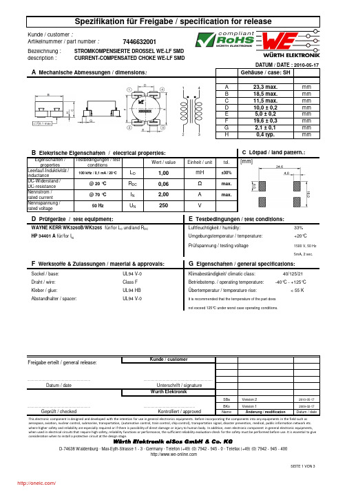
description :Gehäuse / case: SHA 23,3 max.mmB 18,5 max.mmC 11,5 max.mmD 10,0 ± 0,2mmE 5,0 ± 0,2mmF 19,6 ± 0,3mmG 2,1 ± 0,1mm H0,4 typ.mmEigenschaften / propertiesWert / valueEinheit / unittol.Leerlauf-Induktivität /inductanceDC-Widerstand /DC-resistance Nennstrom /rated current Nennspannung /rated voltage33%+20°CPrüfspannung / testing voltage1500 V, 50 Hz 5mA, 2 sec.SBaVersion 22010-05-17BKo Version 12009-02-17NameÄnderung / modificationDatum / dateÜbertemperatur / temperature rise: < 55 KKlimabeständigkeit/ climatic class: 40/125/21.............................................................Datum / dateCURRENT-COMPENSATED CHOKE WE-LF SMDmH R DC WAYNE KERR WK3260B/WK3265für/for L 0 und/and R DC U NI N Luftfeuchtigkeit / humidity:Class F Betriebstemp. / operating temperature: -40°C - +125°C HP 34401 A für/for I N...............................................................................2,00max.0,06±30%B Elektrische Eigenschaften / electrical properties:25050 HzUnterschrift / signatureKontrolliert / approvedWürth Elektronik.................................................................................................................................................................DATUM / DATE : 2010-05-17max.A Testbedingungen / testconditionsVΩA Mechanische Abmessungen / dimensions :100 kHz / 0,1 mA / 20°CC Lötpad / land pattern.:Umgebungstemperatur / temperature:L O 1,00D Prüfgeräte / test equipment:E Testbedingungen / test conditions:@ 20 °C @ 70 °C UL94 HB It is recommended that the temperature of the part does not exceed 125°C under worst case operating conditions.G Eigenschaften / general specifications:Sockel / base:Draht / wire:UL94 V-0F Werkstoffe & Zulassungen / material & approvals:Kleber / glue:Freigabe erteilt / general release:Kunde / customerAbstandhalter / spacer:UL94 V-0Würth Elektronik eiSos GmbH & Co. KGGeprüft / checked This electronic component is designed and developed with the intention for use in general electronics equipments. Before incorporating the components into any equipments in the field such as aerospace, aviation, nuclear control, submarine, transportation, (automotive control, train control, ship control), transportation signal, disaster prevention, medical, public information network etc. where higher safety and reliability are especially required or if there is possibility of direct damage or injury to human body.In addition, even electronic component in general electronic equipments, when used in electrical circuits that require high safety, reliability functions or performance, the sufficient reliability evaluation-check for the safety must be performed before use. It is essential to give consideration when to install a protective circuit at the design stage.[mm]description :SBaVersion 22010-05-17BKoVersion 12009-02-17NameÄnderung / modificationDatum / dateH Einfügungsdämpfung / insertion loss:Freigabe erteilt / general release:Geprüft / checked Kontrolliert / approvedDatum / dateWürth ElektronikWürth Elektronik eiSos GmbH & Co. KG.................................................................................................................................................................CURRENT-COMPENSATED CHOKE WE-LF SMDDATUM / DATE : 2010-05-17Unterschrift / signature ............................................................................................................................................Kunde / customer01020304050600,010,1110E i n f üg u n g s d äm p f u n g / i n s e r t i o n l o s s [d B ]Frequenz / frequency [MHz]typischer Dämpfungsverlauf / typical attenuation curveThis electronic component is designed and developed with the intention for use in general electronics equipments. Before incorporating the components into any equipments in the field such as aerospace, aviation, nuclear control, submarine, transportation, (automotive control, train control, ship control), transportation signal, disaster prevention, medical, public information network etc. where higher safety and reliability are especially required or if there is possibility of direct damage or injury to human body.In addition, even electronic component in general electronic equipments, when used in electrical circuits that require high safety, reliability functions or performance, the sufficient reliability evaluation-check for the safety must be performed before use. It is essential to give consideration when to install a protective circuit at the design stage.description :Gurtspezifikation / Tape specification:A24mmB4mmC44mma330 ± 2,0mmb21 ± 0,8mmc13 ± 0,5mmd150 ±1,0mme48,4mmf44mm165 to 180°SBa Version 22010-05-17BKo Version 12009-02-17NameÄnderung / modification Datum / date Datum / date Unterschrift / signatureWürth Elektronik.............................................................Geprüft / checked Kontrolliert / approvedWürth Elektronik eiSos GmbH & Co. KGI Rollenspezifikation / tape and reel specification:Rollenspezifikation / Reel specification: Freigabe erteilt / general release:Kunde / customer..................................................................................CURRENT-COMPENSATED CHOKE WE-LF SMDDATUM / DATE : 2010-05-17............................................................................... ...............................................................................The force for tearing off cover tape is10 to 130 grams in arrow directionfeeding directionØ ca b dA BefCThis electronic component is designed and developed with the intention for use in general electronics equipments. Before incorporating the components into any equipments in the field such as aerospace, aviation, nuclear control, submarine, transportation, (automotive control, train control, ship control), transportation signal, disaster prevention, medical, public information network etc. where higher safety and reliability are especially required or if there is possibility of direct damage or injury to human body.In addition, even electronic component in general electronic equipments, when used in electrical circuits that require high safety, reliability functions or performance, the sufficient reliability evaluation-check for the safety must be performed before use. It is essential to give consideration when to install a protective circuit at the design stage.分销商库存信息: WURTH-ELECTRONICS 7446632001。
7447789004;中文规格书,Datasheet资料

description := Start of winding Marking = Inductance code33% Umgebungstemperatur / temperature:+20°C100% SnSSt 06-01-10MST 04-10-11SST 04-07-28SST04-04-21SST 04-04-08NameDatum / datenot exceed 125°C under worst case operating conditions.Draht / wire:2SFBW; 155°POWER-CHOKE WE-PD.............................................Umgebungstemp. / ambient temperature: -40°C - + 85°C Basismaterial / base material: Endoberfläche / finishing electrode:D Prüfgeräte / test equipment :E Testbedingungen / test conditions :HP 4274 A für/for L und/and Q F Werkstoffe & Zulassungen / material & approvals :G Eigenschaften / general specifications :Ferrit/ferrite HP 34401 A für/for I DC und/and R DCLuftfeuchtigkeit / humidity:Freigabe erteilt / general release:Kunde / customerAnbindung an Elektrode / soldering wire to plating:Betriebstemp. / operating temperature: -40°C - + 125°C It is recommended that the temperature of the part does Sn/Ag/Cu - 96.5/3.0/0.5%Würth Elektronik................................................................................Datum / date................................................................................Unterschrift / signatureVersion 5Änderung / modificationVersion 1Version 2Version 3Version 4 http://www.we-online.deKontrolliert / approvedWürth Elektronik eiSos GmbH & Co. KGD-74638 Waldenburg · Max-Eyth-Strasse 1 - 3 · Germany · Telefon (+49) (0) 7942 - 945 - 0 · Telefax (+49) (0) 7942 - 945 - 400Geprüft / checked ...................................................description :H Induktivitätskurve / Inductance curve :SSt 06-01-10MST 04-10-11SST 04-07-28SST04-04-21SST 04-04-08NameDatum / datePOWER-CHOKE WE-PDDATUM / DATE : 2006-01-10Würth Elektronik eiSos GmbH & Co. KGD-74638 Waldenburg · Max-Eyth-Strasse 1 - 3 · Germany · Telefon (+49) (0) 7942 - 945 - 0 · Telefax (+49) (0) 7942 - 945 - 400http://www.we-online.de................................................................................................Geprüft / checked Kontrolliert / approvedDatum / dateUnterschrift / signature Würth ElektronikFreigabe erteilt / general release:Kunde / customer................................................................................................................................................................Änderung / modificationVersion 1Version 2Version 3Version 4Version 5description :A 10,0± 0,1B 16,0± 0,2+ 0,1a 330,0± 2,0mm b 21,0± 0,8mm c 13,0± 0,5mm d 100,0± 1,0mm SSt 06-01-10MST 04-10-11SST 04-07-28SST04-04-21SST 04-04-08NameDatum / dateD-74638 Waldenburg · Max-Eyth-Strasse 1 - 3 · Germany · Telefon (+49) (0) 7942 - 945 - 0 · Telefax (+49) (0) 7942 - 945 - 400http://www.we-online.dePOWER-CHOKE WE-PDDATUM / DATE : 2006-01-10Würth ElektronikGeprüft / checked Kontrolliert / approvedWürth Elektronik eiSos GmbH & Co. KG................................................................................................Änderung / modificationVersion 1Version 2Freigabe erteilt / general release:Kunde / customerDatum / dateUnterschrift / signature ................................................................................................................................................................Rollenspezifikation / Reel specification:Version 3Version 4Version 51,50C Gurtspezifikation / Tape specification: The force for tearing off cover tape is 10 to 130 grams in arrow directionfeeding directionThis electronic component has been designed and developed for usage in general electronic equipment. Before incorporating this component into any equipment where higher safety and reliability is especially required or if there is the possibility of direct damage or injury to human body, for example in the range of aerospace, aviation, nuclear control, submarine, transportation, (automotive control, train control, ship control), transportation signal, disaster prevention, medical, public information network etc, Würth Elektronik eiSos GmbH must be informed before the design-in stage. In addition, sufficient reliability evaluation checks for safety must be performed on every electronic component which is used in electrical circuits that require high safety and reliability functions or performance.分销商库存信息: WURTH-ELECTRONICS 7447789004。
AO8814;中文规格书,Datasheet资料
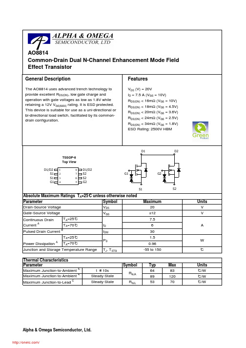
Symbol V DS V GSI DM T J , T STG SymbolTyp Max 648389120R θJL5370Junction and Storage Temperature Range AP D °CT A =70°CI D Pulsed Drain Current BPower Dissipation AT A =25°CContinuous Drain Current AUnits Parameter T A =25°C T A =70°CAbsolute Maximum Ratings T A =25°C unless otherwise noted V V Gate-Source Voltage Drain-Source Voltage °C/W Maximum Junction-to-Ambient A Steady-State °C/W W Maximum Junction-to-Lead CSteady-State°C/WThermal CharacteristicsParameterUnits Maximum Junction-to-Ambient A t ≤ 10sR θJA AO8814Common-Drain Dual N-Channel Enhancement Mode Field Effect TransistorG1S1S1D1/D2G2S2S2D1/D212348765TSSOP-8Top ViewGeneral DescriptionThe AO8814 uses advanced trench technology to provide excellent R DS(ON), low gate charge and operation with gate voltages as low as 1.8V while retaining a 12V V GS(MAX) rating. It is ESD protected.This device is suitable for use as a uni-directional or bi-directional load switch, facilitated by its common-drain configuration.SymbolMin TypMaxUnits BV DSS 20V 1T J =55°C 5I GSS 10µA BV GSO ±12V V GS(th)0.50.711V I D(ON)30A 101316T J =125°C14182211.51518m Ω1316.820m Ω151924m Ω202634m Ωg FS 30S V SD 0.741V I S2.5A C iss 1390pF C oss 190pF C rss 150pF R g1.5ΩQ g 15.4nC Q gs 1.4nC Q gd 4nC t D(on) 6.2ns t r 11ns t D(off)40.5ns t f 10ns t rr 15ns Q rr5.1nCTHIS PRODUCT HAS BEEN DESIGNED AND QUALIFIED FOR THE CONSUMER MARKET. APPLICATIONS OR USES AS CRITICAL COMPONENTS IN LIFE SUPPORT DEVICES OR SYSTEMS ARE NOT AUTHORIZED. AOS DOES NOT ASSUME ANY LIABILITY ARISING OUT OF SUCH APPLICATIONS OR USES OF ITS PRODUCTS. AOS RESERVES THE RIGHT TO IMPROVE PRODUCT DESIGN,FUNCTIONS AND RELIABILITY WITHOUT NOTICE.Maximum Body-Diode Continuous CurrentInput Capacitance Output CapacitanceGate-Source Breakdown Voltage V DS =0V, I G =±250uA V GS =3.6V, I D =6A Turn-On DelayTime DYNAMIC PARAMETERSV GS =0V, V DS =10V, f=1MHz Gate Drain Charge Turn-On Rise Time Turn-Off DelayTime V GS =5V, V DS =10V, R L =1.3Ω,R GEN =3ΩGate resistanceV GS =0V, V DS =0V, f=1MHzTurn-Off Fall TimeSWITCHING PARAMETERS Total Gate Charge V GS =4.5V, V DS =10V, I D =7.5AGate Source Charge m ΩV GS =2.5V, I D =6A I S =1A,V GS =0VV DS =5V, I D =7.5A V GS =1.8V, I D =5AV GS =4.5V, I D =7A R DS(ON)Static Drain-Source On-ResistanceForward Transconductance Diode Forward VoltageI DSS µA Gate Threshold Voltage V DS =V GS I D =250µA V DS =16V, V GS =0VZero Gate Voltage Drain Current V DS =0V, V GS =±10V Gate-Body leakage current Electrical Characteristics (T J =25°C unless otherwise noted)STATIC PARAMETERSParameterConditions Body Diode Reverse Recovery TimeBody Diode Reverse Recovery Charge I F =7.5A, dI/dt=100A/µsDrain-Source Breakdown Voltage On state drain currentI D =250µA, V GS =0V V GS =4.5V, V DS =5V V GS =10V, I D =7.5AReverse Transfer Capacitance I F =7.5A, dI/dt=100A/µsA: The value of R θJA is measured with the device mounted on 1in 2 FR-4 board with 2oz. Copper, in a still air environment with T A =25°C.The value in any given application depends on the user's specific board design. The current rating is based on the t ≤ 10s thermal resistance rating.B: Repetitive rating, pulse width limited by junction temperature.C. The R θJA is the sum of the thermal impedence from junction to lead R θJL and lead to ambient.D. The static characteristics in Figures 1 to 6,12,14 are obtained using <300 µs pulses, duty cycle 0.5% max.E. These tests are performed with the device mounted on 1 in 2 FR-4 board with 2oz. Copper, in a still air environment with T A =25°C. The SOA curve provides a single pulse rating.Rev 5: Feb 2010分销商库存信息: AOSAO8814。
0878320826;中文规格书,Datasheet资料

This document was generated on 08/16/2012PLEASE CHECK FOR LATEST PART INFORMATIONPart Number:87832-0826Status:ActiveOverview:Milli-Grid™ Connector SystemDescription:2.00mm Pitch Milli-Grid™ Header, Surface Mount, Vertical, Shrouded, Lead-Free, 8Circuits, 0.38µm Gold (Au) Plating, without PCB Locator, with Locking Window, Pick-and-Place Cap, TubeDocuments:3D ModelProduct Specification PS-87831-027 (PDF)Drawing (PDF)RoHS Certificate of Compliance (PDF)Agency CertificationCSA LR19980ULE29179GeneralProduct Family PCB Headers Series87832Application Signal, Wire-to-BoardComments With Cap|Contact Molex for application in automotive industryOverviewMilli-Grid™ Connector System Product Name Milli-Grid™UPC822348378326PhysicalBreakawayNo Circuits (Loaded)8Circuits (maximum)8Color - ResinBlack Durability (mating cycles max)100First Mate / Last Break No Flammability94V-0Glow-Wire Compliant No Guide to Mating Part No Keying to Mating Part Yes Lock to Mating Part YesMaterial - MetalPhosphor Bronze Material - Plating MatingGold Material - Plating Termination Tin Material - Resin Nylon Net Weight0.547/g Number of Rows 2Orientation Vertical PCB Locator No PCB Retention None Packaging TypeTube Pitch - Mating Interface2.00mm Pitch - Termination Interface 2.00mm Plating min - Mating0.381µm Plating min - Termination 1.905µm Polarized to PCB No Shrouded Fully StackableNo Surface Mount Compatible (SMC)YesTemperature Range - Operating-55°C to +105°CSeriesimage - Reference onlyEU RoHSChina RoHSELV and RoHS Compliant REACH SVHCContains SVHC: No Low-Halogen Status Not Low-HalogenNeed more information on product environmental compliance?Email productcompliance@For a multiple part number RoHS Certificate of Compliance, click herePlease visit the Contact Us section for any non-product compliance questions.Search Parts in this Series 87832SeriesMates With50394 Wire-to-Board Terminals, 51110Wire-to-Board Crimp Housing, 87568 Wire-to-Board IDT Housings, 79107 Board-to-Board Top Entry Through Hole Receptacle,79108 Board-to-Board FFC/FPC Top Entry Through Hole Receptacle, LTermination Interface: Style Through Hole and Surface MountElectricalCurrent - Maximum per Contact2AVoltage - Maximum125VMaterial InfoReference - Drawing NumbersProduct Specification PS-87831-027Sales Drawing SD-87832-030This document was generated on 08/16/2012PLEASE CHECK FOR LATEST PART INFORMATION分销商库存信息: MOLEX 0878320826。
- 1、下载文档前请自行甄别文档内容的完整性,平台不提供额外的编辑、内容补充、找答案等附加服务。
- 2、"仅部分预览"的文档,不可在线预览部分如存在完整性等问题,可反馈申请退款(可完整预览的文档不适用该条件!)。
- 3、如文档侵犯您的权益,请联系客服反馈,我们会尽快为您处理(人工客服工作时间:9:00-18:30)。
This document was generated on 08/07/2012
PLEASE CHECK FOR LATEST PART INFORMATION
Part Number:87568-1444Status:Active
Overview:Milli-Grid™ Connector System
Description:
2.00mm Pitch Milli-Grid™ Cable-to-Board Receptacle, Dual Row, IDT, Lead-Free, 14Circuits, 0.76µm Gold (Au) Selective Plating, with Center Polarization Key, without Locking Friction Ramp
Documents:3D Model
Product Specification PS-87568-004 (PDF)Drawing (PDF)
RoHS Certificate of Compliance (PDF)
Agency Certification
CSA LR19980UL
E29179
General
Product Family IDT and Solder Connectors Series
87568Crimp Quality Equipment Yes
Overview
Milli-Grid™ Connector System Product Name Milli-Grid™UPC 822348457540
Use With
875691014 Strain Relief (Optional)Physical
Circuits (Loaded)14Circuits (maximum)14Color - Resin
Black Durability (mating cycles max)100Flammability 94V-0Gender
Female Glow-Wire Compliant No Lock to Mating Part None
Material - Metal
Copper Alloy Material - Plating Mating Gold
Material - Resin Polyester Net Weight
0.882/g Number of Rows 2Packaging Type Tray Panel Mount
No
Pitch - Mating Interface 2.00mm Polarized to Mating Part Yes Stackable
No
Temperature Range - Operating -20°C to +85°C Termination Interface: Style IDT or Pierce Wire Size AWG
28Electrical
Current - Maximum per Contact 1A Voltage - Maximum
125V
Material Info
Reference - Drawing Numbers
Product Specification PS-87568-004Sales Drawing
SD-87568-003
Series
image - Reference only
EU RoHS
China RoHS
ELV and RoHS Compliant REACH SVHC
Contains SVHC: No Low-Halogen Status Not Low-Halogen
Need more information on product environmental compliance?
Email productcompliance@
For a multiple part number RoHS Certificate of Compliance, click here
Please visit the Contact Us section for any non-product compliance questions.
Search Parts in this Series 87568Series
Mates With
87831 Vertical PCB Header, 87832 Surface Mount PCB Header, 87833 Right Angle PCB Header
Application Tooling | FAQ
Tooling specifications and manuals are found by selecting the products below.Crimp Height Specifications are then contained in the Application Tooling Specification document.Global
Description Product #IDT - Manual -Handtool
0621002000
Manual Press with IDT Ribbon Cable Tool Kit
0621002200IDT Ribbon Cable Adapter Kit for 2.00mm
0621002400
IDT - Manual - Tool
0621003200
Kit
This document was generated on 08/07/2012
PLEASE CHECK FOR LATEST PART INFORMATION
分销商库存信息: MOLEX 0875681444。