对注塑成型工艺参数优化的一般框架(翻译)
注塑模具工艺立体光照成型毕业论文中英文对照资料外文翻译文献

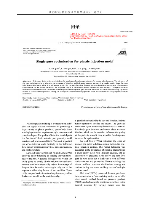
注塑模具工艺中英文对照资料外文翻译文献附录2Integrated simulation of the injection molding process withstereolithography moldsAbstract Functional parts are needed for design verification testing, field trials, customer evaluation, and production planning. By eliminating multiple steps, the creation of the injection mold directly by a rapid prototyping (RP) process holds the best promise of reducing the time and cost needed to mold low-volume quantities of parts. The potential of this integration of injection molding with RP has been demonstrated many times. What is missing is the fundamental understanding of how the modifications to the mold material and RP manufacturing process impact both the mold design and the injection molding process. In addition, numerical simulation techniques have now become helpful tools of mold designers and process engineers for traditional injection molding. But all current simulation packages for conventional injection molding are no longer applicable to this new type of injection molds, mainly because the property of the mold material changes greatly. In this paper, an integrated approach to accomplish a numerical simulation of injection molding into rapid-prototyped molds is established and a corresponding simulation system is developed. Comparisons with experimental results are employed for verification, which show that the present scheme is well suited to handle RP fabricated stereolithography (SL) molds.Keywords Injection molding Numerical simulation Rapid prototyping1 IntroductionIn injection molding, the polymer melt at high temperature is injected into the mold under high pressure [1]. Thus, the mold material needs to have thermal and mechanical properties capable of withstanding the temperatures and pressures of the molding cycle. The focus of many studies has been to create theinjection mold directly by a rapid prototyping (RP) process. By eliminating multiple steps, this method of tooling holds the best promise of reducing the time and cost needed to createlow-volume quantities of parts in a production material. The potential of integrating injection molding with RP technologies has been demonstrated many times. The properties of RP molds are very different from those of traditional metal molds. The key differences are the properties of thermal conductivity and elastic modulus (rigidity). For example, the polymers used in RP-fabricated stereolithography (SL) molds have a thermal conductivity that is less than one thousandth that of an aluminum tool. In using RP technologies to create molds, the entire mold design and injection-molding process parameters need to be modified and optimized from traditional methodologies due to the completely different tool material. However, there is still not a fundamental understanding of h ow the modifications to the mold tooling method and material impact both the mold design and the injection molding process parameters. One cannot obtain reasonable results by simply changing a few material properties in current models. Also, using traditional approaches when making actual parts may be generating sub-optimal results. So there is a dire need to study the interaction between the rapid tooling (RT) process and material and injection molding, so as to establish the mold design criteria and techniques for an RT-oriented injection molding process.In addition, computer simulation is an effective approach for predicting the quality of molded parts. Commercially available simulation packages of the traditional injection molding process have now become routine tools of the mold designer and process engineer [2]. Unfortunately, current simulation programs for conventional injection molding are no longer applicable to RP molds, because of the dramatically dissimilar tool material. For instance, in using the existing simulation software with aluminum and SL molds and comparing with experimental results, though the simulation values of part distortion are reasonable for the aluminum mold, results are unacceptable, with the error exceeding 50%. The distortion during injection molding is due to shrinkage and warpage of the plastic part, as well as the mold. For ordinarily molds, the main factor is the shrinkage and warpage of the plastic part, which is modeled accurately in current simulations. But for RP molds, the distortion of the mold has potentially more influence, which have been neglected in current models. For instance, [3] used a simple three-step simulation process to consider the mold distortion, which had too much deviation.In this paper, based on the above analysis, a new simulation system for RP molds is developed. The proposed system focuses on predicting part distortion, which is dominating defect in RP-molded parts. The developed simulation can be applied as an evaluation tool for RP mold design and process opti mization. Our simulation system is verified by an experimental example.Although many materials are available for use in RP technologies, we concentrate on usingstereolithography (SL), the original RP technology, to create polymer molds. The SL process uses photopolymer and laser energy to build a part layer by layer. Using SL takes advantage of both the commercial dominance of SL in the RP industry and the subsequent expertise base that has been developed for creating accurate, high-quality parts. Until recently, SL was primarily used to create physical models for visual inspection and form-fit studies with very limited func-tional applications. However, the newer generation stereolithographic photopolymers have improved dimensional, mechanical and thermal properties making it possible to use them for actual functional molds.2 Integrated simulation of the molding process2.1 MethodologyIn order to simulate the use of an SL mold in the injection molding process, an iterative method is proposed. Different software modules have been developed and used to accomplish this task. The main assumption is that temperature and load boundary conditions cause significant distortions in the SL mold. The simulation steps are as follows:1T he part geometry is modeled as a solid model, which is translated to a file readable by the flow analysis package.2Simulate the mold-filling process of the melt into a pho topolymer mold, which will output the resulting temperature and pressure profiles.3Structural analysis is then performed on the photopolymer mold model using the thermal and load boundary conditions obtained from the previous step, which calculates the distortion that the mold undergo during the injection process.4If the distortion of the mold converges, move to the next step. Otherwise, the distorted mold cavity is then modeled (changes in the dimensions of the cavity after distortion), and returns to the second step to simulate the melt injection into the distorted mold.5The shrinkage and warpage simulation of the injection molded part is then applied, which calculates the final distor tions of the molded part.In above simulation flow, there are three basic simulation mod ules.2. 2 Filling simulation of the melt2.2.1 Mathematical modelingIn order to simulate the use of an SL mold in the injection molding process, an iterativemethod is proposed. Different software modules have been developed and used to accomplish this task. The main assumption is that temperature and load boundary conditions cause significant distortions in the SL mold. The simulation steps are as follows:1. The part geometry is modeled as a solid model, which is translated to a file readable by the flow analysis package.2. Simulate the mold-filling process of the melt into a photopolymer mold, which will output the resulting temperature and pressure profiles.3. Structural analysis is then performed on the photopolymer mold model using the thermal and load boundary conditions obtained from the previous step, which calculates the distortion that the mold undergo during the injection process.4. If the distortion of the mold converges, move to the next step. Otherwise, the distorted mold cavity is then modeled (changes in the dimensions of the cavity after distortion), and returns to the second step to simulate the melt injection into the distorted mold.5. The shrinkage and warpage simulation of the injection molded part is then applied, which calculates the final distortions of the molded part.In above simulation flow, there are three basic simulation modules.2.2 Filling simulation of the melt2.2.1 Mathematical modelingComputer simulation techniques have had success in predicting filling behavior in extremely complicated geometries. However, most of the current numerical implementation is based on a hybrid finite-element/finite-difference solution with the middleplane model. The application process of simulation packages based on this model is illustrated in Fig. 2-1. However, unlike the surface/solid model in mold-design CAD systems, the so-called middle-plane (as shown in Fig. 2-1b) is an imaginary arbitrary planar geometry at the middle of the cavity in the gap-wise direction, which should bring about great inconvenience in applications. For example, surface models are commonly used in current RP systems (generally STL file format), so secondary modeling is unavoidable when using simulation packages because the models in the RP and simulation systems are different. Considering these defects, the surface model of the cavity is introduced as datum planes in the simulation, instead of the middle-plane.According to the previous investigations [4–6], fillinggoverning equations for the flow and temperature field can be written as:where x, y are the planar coordinates in the middle-plane, and z is the gap-wise coordinate; u, v,w are the velocity components in the x, y, z directions; u, v are the average whole-gap thicknesses; and η, ρ,CP (T), K(T) represent viscosity, density, specific heat and thermal conductivity of polymer melt, respectively.Fig.2-1 a–d. Schematic procedure of the simulation with middle-plane model. a The 3-D surface model b The middle-plane model c The meshed middle-plane model d The display of the simulation result In addition, boundary conditions in the gap-wise direction can be defined as:where TW is the constant wall temperature (shown in Fig. 2a).Combining Eqs. 1–4 with Eqs. 5–6, it follows that the distributions of the u, v, T, P at z coordinates should be symmetrical, with the mirror axis being z = 0, and consequently the u, v averaged in half-gap thickness is equal to that averaged in wholegap thickness. Based on this characteristic, we can divide the whole cavity into two equal parts in the gap-wise direction, as described by Part I and Part II in Fig. 2b. At the same time, triangular finite elements are generated in the surface(s) of the cavity (at z = 0 in Fig. 2b), instead of the middle-plane (at z = 0 in Fig. 2a). Accordingly, finite-difference increments in the gapwise direction are employed only in the inside of the surface(s) (wall to middle/center-line), which, in Fig. 2b, means from z = 0 to z = b. This is single-sided instead of two-sided with respect to the middle-plane (i.e. from the middle-line to two walls). In addition, the coordinate system is changed from Fig. 2a to Fig. 2b to alter the finite-element/finite-difference scheme, as shown in Fig. 2b. With the above adjustment, governing equations are still Eqs. 1–4. However, the original boundary conditions inthe gapwise direction are rewritten as:Meanwhile, additional boundary conditions must be employed at z = b in order to keep the flows at the juncture of the two parts at the same section coordinate [7]:where subscripts I, II represent the parameters of Part I and Part II, respectively, and Cm-I and Cm-II indicate the moving free melt-fronts of the surfaces of the divided two parts in the filling stage.It should be noted that, unlike conditions Eqs. 7 and 8, ensuring conditions Eqs. 9 and 10 are upheld in numerical implementations becomes more difficult due to the following reasons:1. The surfaces at the same section have been meshed respectively, which leads to a distinctive pattern of finite elements at the same section. Thus, an interpolation operation should be employed for u, v, T, P during the comparison between the two parts at the juncture.2. Because the two parts have respective flow fields with respect to the nodes at point A and point C (as shown in Fig. 2b) at the same section, it is possible to have either both filled or one filled (and one empty). These two cases should be handled separately, averaging the operation for the former, whereas assigning operation for the latter.3. It follows that a small difference between the melt-fronts is permissible. That allowance can be implemented by time allowance control or preferable location allowance control of the melt-front nodes.4. The boundaries of the flow field expand by each melt-front advancement, so it is necessary to check the condition Eq. 10 after each change in the melt-front.5. In view of above-mentioned analysis, the physical parameters at the nodes of the same section should be compared and adjusted, so the information describing finite elements of the same section should be prepared before simulation, that is, the matching operation among the elements should be preformed.Fig. 2a,b. Illustrative of boundary conditions in the gap-wise direction a of the middle-plane model b of thesurface model2.2.2 Numerical implementationPressure field. In modeling viscosity η, which is a function of shear rate, temperature and pressure of melt, the shear-thinning behavior can be well represented by a cross-type model such as:where n corresponds to the power-law index, and τ∗ characterizes the shear stress level of the transition region between the Newtonian and power-law asymptotic limits. In terms of an Arrhenius-type temperature sensitivity and exponential pressure dependence, η0(T, P) can be represented with reasonable accuracy as follows:Equations 11 and 12 constitute a five-constant (n, τ∗, B, Tb, β) representation for viscosity. The shear rate for viscosity calculation is obtained by:Based on the above, we can infer the following filling pressure equation from the governing Eqs. 1–4:where S is calculated by S = b0/(b−z)2η d z. Applying the Galerkin method, the pressure finite-element equation is deduced as:where l_ traverses all elements, including node N, and where I and j represent the local node number in element l_ corresponding to the node number N and N_ in the whole, respectively. The D(l_) ij is calculated as follows:where A(l_) represents triangular finite elements, and L(l_) i is the pressure trial function in finite elements.Temperature field. To determine the temperature profile across the gap, each triangular finite element at the surface is further divided into NZ layers for the finite-difference grid.The left item of the energy equation (Eq. 4) can be expressed as:where TN, j,t represents the temperature of the j layer of node N at time t.The heat conduction item is calculated by:where l traverses all elements, including node N, and i and j represent the local node number in element l corresponding to the node number N and N_ in the whole, respectively.The heat convection item is calculated by:For viscous heat, it follows that:Substituting Eqs. 17–20 into the energy equation (Eq. 4), the temperature equation becomes:2.3 Structural analysis of the moldThe purpose of structural analysis is to predict the deformation occurring in the photopolymer mold due to the thermal and mechanical loads of the filling process. This model is based on a three-dimensional thermoelastic boundary element method (BEM). The BEM is ideally suited for this application because only the deformation of the mold surfaces is of interest. Moreover, the BEM has an advantage over other techniques in that computing effort is not wasted on calculating deformation within the mold.The stresses resulting from the process loads are well within the elastic range of the mold material. Therefore, the mold deformation model is based on a thermoelastic formulation. The thermal and mechanical properties of the mold are assumed to be isotropic and temperature independent.Although the process is cyclic, time-averaged values of temperature and heat flux are used for calculating the mold deformation. Typically, transient temperature variations within a mold have been restricted to regions local to the cavity surface and the nozzle tip [8]. The transients decay sharply with distance from the cavity surface and generally little variation is observed beyond distances as small as 2.5 mm. This suggests that the contribution from the transients to the deformation at the mold block interface is small, and therefore it is reasonable to neglect the transient effects. The steady state temperature field satisfies Laplace’s equation 2T = 0 and the time-averaged boundary conditions. The boundary conditions on the mold surfaces are described in detail by Tang et al. [9]. As for the mechanical boundary conditions, the cavity surface is subjected to the melt pressure, the surfaces of the mold connected to the worktable are fixed in space, and other external surfaces are assumed to be stress free.The derivation of the thermoelastic boundary integral formulation is well known [10]. It is given by:where uk, pk and T are the displacement, traction and temperature,α, ν represent the thermal expansion coefficient and Poisson’s ratio of the material, and r = |y−x|. clk(x) is the surfacecoefficient which depends on the local geometry at x, the orientation of the coordinate frame and Poisson’s ratio for the domain [11]. The fundamental displacement ˜ulk at a point y in the xk direction, in a three-dimensional infinite isotropic elastic domain, results from a unit load concentrated at a point x acting in the xl direction and is of the form:where δlk is the Kronecker delta function and μ is the shear modulus of the mold material.The fundamental traction ˜plk , measured at the point y on a surface with unit normal n, is:Discretizing the surface of the mold into a total of N elements transforms Eq. 22 to:where Γn refers to the n th surface element on the domain.Substituting the appropriate linear shape functions into Eq. 25, the linear boundary element formulation for the mold deformation model is obtained. The equation is applied at each node on the discretized mold surface, thus giving a system of 3N linear equations, where N is the total number of nodes. Each node has eight associated quantities: three components of displacement, three components of traction, a temperature and a heat flux. The steady state thermal model supplies temperature and flux values as known quantities for each node, and of the remaining six quantities, three must be specified. Moreover, the displacement values specified at a certain number of nodes must eliminate the possibility of a rigid-body motion or rigid-body rotation to ensure a non-singular system of equations. The resulting system of equations is assembled into a integrated matrix, which is solved with an iterative solver.2.4 Shrinkage and warpage simulation of the molded partInternal stresses in injection-molded components are the principal cause of shrinkage and warpage. These residual stresses are mainly frozen-in thermal stresses due to inhomogeneous cooling, when surface layers stiffen sooner than the core region, as in free quenching. Based onthe assumption of the linear thermo-elastic and linear thermo-viscoelastic compressible behavior of the polymeric materials, shrinkage and warpage are obtained implicitly using displacement formulations, and the governing equations can be solved numerically using a finite element method.With the basic assumptions of injection molding [12], the components of stress and strain are given by:The deviatoric components of stress and strain, respectively, are given byUsing a similar approach developed by Lee and Rogers [13] for predicting the residual stresses in the tempering of glass, an integral form of the viscoelastic constitutive relationships is used, and the in-plane stresses can be related to the strains by the following equation:Where G1 is the relaxation shear modulus of the material. The dilatational stresses can be related to the strain as follows:Where K is the relaxation bulk modulus of the material, and the definition of α and Θ is:If α(t) = α0, applying Eq. 27 to Eq. 29 results in:Similarly, applying Eq. 31 to Eq. 28 and eliminating strain εxx(z, t) results in:Employing a Laplace transform to Eq. 32, the auxiliary modulus R(ξ) is given by:Using the above constitutive equation (Eq. 33) and simplified forms of the stresses and strains in the mold, the formulation of the residual stress of the injection molded part during the cooling stage is obtain by:Equation 34 can be solved through the application of trapezoidal quadrature. Due to the rapid initial change in the material time, a quasi-numerical procedure is employed for evaluating the integral item. The auxiliary modulus is evaluated numerically by the trapezoidal rule.For warpage analysis, nodal displacements and curvatures for shell elements are expressed as:where [k] is the element stiffness matrix, [Be] is the derivative operator matrix, {d} is the displacements, and {re} is the element load vector which can be evaluated by:The use of a full three-dimensional FEM analysis can achieve accurate warpage results, however, it is cumbersome when the shape of the part is very complicated. In this paper, a twodimensional FEM method, based on shell theory, was used because most injection-molded parts have a sheet-like geometry in which the thickness is much smaller than the other dimensions of the part. Therefore, the part can be regarded as an assembly of flat elements to predict warpage. Each three-node shell element is a combination of a constant strain triangular element (CST) and a discrete Kirchhoff triangular element (DKT), as shown in Fig. 3. Thus, the warpage can be separated into plane-stretching deformation of the CST and plate-bending deformation of the DKT, and correspondingly, the element stiffness matrix to describe warpage can also be divided into the stretching-stiffness matrix and bending-stiffness matrix.Fig. 3a–c. Deformation decomposition of shell element in the local coordinate system. a In-plane stretchingelement b Plate-bending element c Shell element3 Experimental validationTo assess the usefulness of the proposed model and developed program, verification is important. The distortions obtained from the simulation model are compared to the ones from SL injection molding experiments whose data is presented in the literature [8]. A common injection molded part with the dimensions of 36×36×6 mm is considered in the experiment, as shown in Fig. 4. The thickness dimensions of the thin walls and rib are both 1.5 mm; and polypropylene was used as the injection material. The injection machine was a production level ARGURY Hydronica 320-210-750 with the following process parameters: a melt temperature of 250 ◦C; an ambient temperature of 30 ◦C; an injection pressure of 13.79 MPa; an injection time of 3 s; and a cooling time of 48 s. The SL material used, Dupont SOMOSTM 6110 resin, has the ability to resist temperatures of up to 300 ◦C temperatures. As mentioned above, thermal conductivity of the mold is a major factor that differentiates between an SL and a traditional mold. Poor heat transfer in the mold would produce a non-uniform temperature distribution, thus causing warpage that distorts the completed parts. For an SL mold, a longer cycle time would be expected. The method of using a thin shell SL mold backed with a higher thermal conductivity metal (aluminum) was selected to increase thermal conductivity of the SL mold.Fig. 4. Experimental cavity modelFig. 5. A comparison of the distortion variation in the X direction for different thermal conductivity; where “Experimental”, “present”, “three-step”, and “conventional” mean the results of the experimental, the presented simulation, the three-step simulation process and the conventional injection molding simulation, respectively.Fig. 6. Comparison of the distortion variation in the Y direction for different thermal conductivitiesFig. 7. Comparison of the distortion variation in the Z direction for different thermal conductivitiesFig. 8. Comparison of the twist variation for different thermal conductivities For this part, distortion includes the displacements in three directions and the twist (the difference in angle between two initially parallel edges). The validation results are shown in Fig.5 to Fig. 8. These figures also include the distortion values predicted by conventional injection molding simulation and the three-step model reported in [3].4 ConclusionsIn this paper, an integrated model to accomplish the numerical simulation of injection molding into rapid-prototyped molds is established and a corresponding simulation system is developed. For verification, an experiment is also carried out with an RPfabricated SL mold.It is seen that a conventional simulation using current injection molding software breaks down for a photopolymer mold. It is assumed that this is due to the distortion in the mold caused by the temperature and load conditions of injection. The three-step approach also has much deviation. The developed model gives results closer to experimental.Improvement in thermal conductivity of the photopolymer significantly increases part quality. Since the effect of temperature seems to be more dominant than that of pressure (load), an improvement in the thermal conductivity of the photopolymer can improve the part quality significantly.Rapid Prototyping (RP) is a technology makes it possible to manufacture prototypes quickly and inexpensively, regardless of their comp lexity. Rapid Tooling (RT) is the next step in RP’s steady progress and much work is being done to obtain more accurate tools to define the parameters of the process. Existing simulation tools can not provide the researcher with a useful means of studying relative changes. An integrated model, such as the one presented in this paper, is necessary to obtain accurate predictions of the actual quality of final parts. In the future, we expect to see this work expanded to develop simulations program for injection into RP molds manufactured by other RT processes.References1. Wang KK (1980) System approach to injection molding process. Polym-Plast Technol Eng 14(1):75–93.2. Shelesh-Nezhad K, Siores E (1997) Intelligent system for plastic injection molding process design. J Mater Process Technol 63(1–3):458–462.3. Aluru R, Keefe M, Advani S (2001) Simulation of injection molding into rapid-prototyped molds. Rapid Prototyping J 7(1):42–51.4. Shen SF (1984) Simulation of polymeric flows in the injection molding process. Int J Numer Methods Fluids 4(2):171–184.5. Agassant JF, Alles H, Philipon S, Vincent M (1988) Experimental and theoretical study of the injection molding of thermoplastic materials. Polym Eng Sci 28(7):460–468.6. Chiang HH, Hieber CA, Wang KK (1991) A unified simulation of the filling and post-filling stages in injection molding. Part I: formulation. Polym Eng Sci 31(2):116–124.7. Zhou H, Li D (2001) A numerical simulation of the filling stage in injection molding based on a surface model. Adv Polym Technol 20(2):125–131.8. Himasekhar K, Lottey J, Wang KK (1992) CAE of mold cooling in injection molding using a three-dimensional numerical simulation. J EngInd Trans ASME 114(2):213–221.9. Tang LQ, Pochiraju K, Chassapis C, Manoochehri S (1998) Computeraided optimization approach for the design of injection mold cooling systems. J Mech Des, Trans ASME 120(2):165–174.10. Rizzo FJ, Shippy DJ (1977) An advanced boundary integral equation method for three-dimensional thermoelasticity. Int J Numer Methods Eng 11:1753–1768.11. Hartmann F (1980) Computing the C-matrix in non-smooth boundary points. In: New developments in boundary element methods, CML Publications, Southampton, pp 367–379.12. Chen X, Lama YC, Li DQ (2000) Analysis of thermal residual stress in plastic injection molding. J Mater Process Technol 101(1):275–280.13. Lee EH, Rogers TG (1960) Solution of viscoelastic stress analysis problems using measured creep or relaxation function. J Appl Mech 30(1):127–134.14. Li Y (1997) Studies in direct tooling using stereolithography. Dissertation, University of Delaware, Newark, DE..。
(精编)模具注塑术语中英文对照
(精编)模具注塑术语中英文对照(精编)模具注塑术语中英文对照根据国家标准,以下为部分塑料模具成形术语的标准翻译。
动模MovableMouldMovingHalf定模座板FixedClampPlateTopClampingPlateTopPlate动模座板MovingClampPlateBottomClampingPlateBottomPlate上模座板UpperClampingPlate下模座板LowerClampingPlate凹模固定板Cavity-retainerPlate 型芯固定板MouldCore-retainerPlate凸模固定板Punch-retainerPlate模套DieBodyDieSleeveDieBlank支承板BackingPlateSupportPlate垫块SpacerParallel支架EjectorHousingMouldBaseLeg模头DieHead模具分类8InjectionMold注塑模PlasticRubberMould塑胶模RubberMolding橡胶成形HotChamberDieCasting热室压铸SandMoldCasting砂模铸造ExtrusionMold挤出模Multi-CavityMold多模穴模具PalletizingDie叠层模PlasterMold石膏模ThreePlatesMold三板模PlainDie简易模PierceDie冲孔模FormingDie成型模ProgressiveDie连续模GangDies复合模ShearingDie剪边模CavityDie型腔模RivetingDie铆合模CompressionMolding压缩成型FlashMold溢流式模具ExtrusionMold挤压式模具SplitMold分割式模具MouldCavity型腔母模MoldCore模芯公模LargeDieMold大型模具PreciseDieMold 精密模具ComplexDieMold复杂模具FoamingMould发泡模具MetalDie金属模具PlasticMold塑料模具ToolStampingDiePunchDie冲压模具ExtrusionDie挤压模具GraphiteDie石墨模具流道浇口部分RunnerSystem浇道系统SprueColdMaterialTrap浇道冷料井SpruePuller拉杆RunnerDesign流道设计MainRunner主流道SecondaryRunner 次流道MouldGateDesign浇口设计SubmarineGate潜伏浇口TunnelGate隧道式浇口PinpointGate点浇口FanGate扇形浇口SideGate侧浇口EdgeGate侧缘浇口TabGate 搭接浇口FilmGate薄膜浇口FlashGate闸门浇口SlitGate缝隙浇口DishGate盘形浇口DiaphragmGate隔膜浇口RingGate环形浇口Runnerless无浇道Sprueless无射料管方式LongNozzle延长喷嘴方式Sprue浇口,溶渣Insulated/HotRunner热浇道RunnerPlat 浇道模块ValveGate阀门浇口SlagWell冷料井ColdSlag冷料渣SprueGate射料浇口Nozzle 射嘴SprueLockPin料头钩销(拉料杆)注塑缺陷Flash飞边Warpage翘曲AirTrap积风Blush发赤FlowLine流痕Splay银纹ShortShot 短射SinkMark缩痕Streak条纹Void缩孔WeldLine熔接线GasMark烧焦ColdSlug冷斑Delamination起皮Burr毛刺FlawScratch刮伤Gloss光泽Glazing光滑SurfaceCheck表面裂痕Hesitation迟滞注塑工艺MoldingConditions成型条件Drying烘干BarrelTemperature 料筒温度MeltTemperature熔化温度MoldTemperature模具温度InjectionPressure注塑压力BackPressure背压InjectionSpeed注塑速度ScrewSpeed螺杆转速TensileStrength抗拉强度T ensileElongation延伸率FlexuralModulus弯曲模FlexuralStrength抗弯强度Shrinkage收缩率RegrindUsage次料使用Moulding模塑机械设备Lathe车床Planer刨床Miller/MillingMachine铣床Grinder磨床Driller钻床LinearCutting线切割ElectricalSparkle电火花Welder电焊机PunchingMachine冲床Robot机械手CommonEquipment 常用设备EDMElectronDischargeMachining放电加工3DCoordinateMeasurement三次元量床BoringMachine搪孔机ContouringMachine轮廓锯床CopyGrindingMachine仿形磨床CylindricalGrindingMachine外圆磨床DieSpottingMachine合模机EngravingMachine 雕刻机EngravingE.D.M雕模放置加工机FormGrindingMachine成形磨床GraphiteMachine石墨加工机HorizontalBoringMachine卧式搪孔机HorizontalMachineCenter卧式加工制造中心InternalCylindricalMachine内圆磨床模具零件TopPlate上托板(顶板)T opBlock上垫脚PunchSet上模座PunchPad上垫板PunchHolder上夹板StripperPad脱料背板UpStripper上脱料板MaleDie公模(凸模)FeatureDie公母模FemaleDie母模(凹模)UpperMoldPlate上模板LowerMoldPlate 下模板DiePad下垫板DieHolder下夹板DieSet下模座BottomBlock下垫脚BottomPlate下托板(底板)StrippingPlate内外打(脱料板)OuterStripper外脱料板InnerStripper内脱料板LowerStripper下脱料板InnerGuidingPost 内导柱InnerHexagonScrew内六角螺钉DowelPin固定销MouldCoilSpring模具弹簧LifterPin 顶料销IsoheightSleeve等高套筒Pin销LifterGuidePin浮升导料销GuidePin导正销WireSpring圆线弹簧OuterGuidingPost外导柱StopScrew止付螺丝LocatedPin定位销OuterBush外导套Punch冲头Insert入块(嵌入件)DeburringPunch压毛边冲子GroovePunch压线冲子StampedPunch字模冲子RoundPunch圆冲子SpecialShapePunch 异形冲子BendingBlock折刀Roller滚轴BafflePlate挡块LocatedBlock定位块SupportingBlockforLocation定位支承块AirCushionPlate气垫板Air-CushionEject-rod 气垫顶杆TrimmingPunch切边冲子StiffeningRibPunchStinger加强筋冲子RibbonPunch压筋冲子Reel-stretchPunch卷圆压平冲子GuidePlate定位板SlidingBlock滑块SlidingDowelBlock滑块固定块ActivePlate活动板LowerSlidingPlate 下滑块板UpperHolderBlock上压块UpperMidPlate上中间板SpringBox弹簧箱Spring-BoxEject-rod弹簧箱顶杆Spring-BoxEjec模具技术用语各种常用模具成形方式AccurateDieCasting精密压铸PowderForming粉末成形CalendaringMolding压延成形PowderMetalForging粉末锻造ColdChamberDieCasting冷式压铸PrecisionForging 精密锻造ColdForging冷锻PressForgingstampforging冲锻CompactingMolding粉末压出成形RockingDieForging摇动锻造CompoundMolding复合成形RotaryForging回转锻造CompressionMolding压缩成形RotationalMolding离心成形DipMold浸渍成形RubberMolding橡胶成形EncapsulationMolding注入成形SandMoldCasting砂模铸造ExtrusionMolding挤出成形ShellCasting壳模铸造FoamForming 发泡成形SinterForging烧结锻造ForgingRoll轧锻SixSidesForging 六面锻造GravityCasting重力铸造SlushMolding凝塑成形HollowBlowMolding中空(吹出)成形SqueezeCasting高压铸造HotChamberDieCasting热室压铸Swaging挤锻HotForging 热锻TransferMolding转送成形InjectionMolding射出成形WarmForging温锻InvestmentCasting精密铸造MatchedDieMethod对模成形法LaminatingMethod被覆淋膜成形LowPressureCasting低压铸造LostWaxCasting脱蜡铸造MatchedMouldThermalForming对模热成形模CloseMold合模Demould脱模脱模剂MouldUnloading开模ToolChangeRetoolingDieChanging换模MouldClamping锁模各式模具分类用语BismuthMold铋铸模LandedPlungerMold有肩柱塞式模具BurnishingDie挤光模LandedPositiveMold有肩全压式模具ButtonDie镶入式圆形凹模LoadingShoeMold料套式模具Center-GatedMold中心浇口式模具LooseDetailMold活零件模具ChillMold冷硬用铸模LooseMold活动式模具ColdHobbing冷挤压制模法LouveringDie百叶窗冲切模CompositeDies复合模具ManifoldDie分歧管模具CounterPunch反凸模ModularMold组合模具DoubleStackMold双层模具Multi-CavityMold多模穴模具ElectroformedMold电铸成形模Multi-GateMold复式浇口模具ExpanderDie扩径模OffsetColdBendingDie双折冷弯模具ExtrusionDie挤出模PalletizingDie叠层模FamilyMold反套制品模具PlasterMold石膏模BlankThroughDies漏件式落料模PorousMold通气性模具DuplicatedCavityPlate复板模PositiveMold全压式模具FantailDie扇尾形模具PressureDie压紧模FishtailDie鱼尾形模具ProfileDie轮廓模FlashMold溢料式模具ProgressiveDie顺序模GypsumMold石膏铸模PortableMold手提式模具Hot-RunnerMold热流道模具PrototypeMold雏形试验模具原型模具IngotMold钢锭模PunchingDie落料模LancingDie切口模切缝模Raising(Embossing)压花起伏成形Re-entrantMold倒角式模具SectionalDie拼合模RunlessInjectionMold无流道冷料模具SectionalDie对合模具SegmentMold组合模Semi-PositiveMold半全压式模具Shaper 定型模套SingleCavityMold单腔模具SolidForgingDie整体锻模SplitForgingDie拼合锻模SplitMold双并式模具SpruelessMold无注道残料模具SqueezingDie挤压模StretchFormDie拉伸成形模SweepingMold 平刮铸模SwingDie振动模具ThreePlatesMold三片式模具TrimmingDie切边模UnitMold单元式模具UniversalMold 通用模具UnscrewingMold退扣式模具YokeTypeDie轭型模t-Plate弹簧箱顶板BushingBlockLinerBushing衬套CoverPlate盖板GuidePad导料块模具厂常用之标准零配件AirVentValve通气阀AnchorPin锚梢AngularPin角梢Baffle调节阻板AngularPin倾斜梢BafflePlate折流档板BallButton球塞套BallPlunger定位球塞BallSlider球塞滑块BinderPlate压板BlankHolder防皱压板BlankingDie落料冲头Bolster上下模板Bottomboard浇注底板Bolster垫板BottomPlate下固定板Bracket托架BumperBlock 缓冲块Buster堵口CastingLadle浇注包Castinglug铸耳Cavity模穴(模仁)CavityRetainerPlate模穴托板CenterPin中心梢ClampingBlock 锁定块CoilSpring螺旋弹簧ColdPunchedNut冷冲螺母CoolingSpiral螺旋冷却栓Core心型CorePin心型梢Cotter开口梢Cross十字接头CushionPin缓冲梢DiaphragmGate盘形浇口DieApproach模头料道DieBed型底DieBlock块形模体DieBody铸模座DieBush合模衬套DieButton冲模母模DieClamper夹模器DieFastener模具固定用零DieHolder母模固定板DieLip模唇DiePlate冲模板DieSet冲压模座DirectGate直接浇口DogChuck爪牙夹头Dowel定位梢DowelHole导套孔DowelPin合模梢Dozzle辅助浇口DowelPin定位梢Draft拔模锥度DrawBead张力调整杆DriveBearing传动轴承EjectionPad顶出衬垫Ejector脱模器EjectorGuidePin顶出导梢EjectorLeaderBush顶出导梢衬套EjectorPad顶出垫EjectorPin 顶出梢EjectorPlate顶出板EjectorRod顶出杆EjectorSleeve顶出衬套EjectorValve顶出阀EyeBolt环首螺栓FillingCore填充型芯椿入蕊FilmGate薄膜形浇口FingerPin指形梢FinishMachinedPlate 角形模板FinishMachinedRoundPlate圆形模板FixedBolsterPlate固定侧模板FlangedPin带凸缘针FlashGate毛边形浇口Flask上箱FloatingPunch浮动冲头Gate浇口GateLand浇口面Gib凹形拉紧楔GooseNeck鹅颈管GuideBushing引导衬套GuidePin导梢GuidePost 引导柱GuidePlate导板GuideRail导轨HeadPunch顶头冲孔HeadlessPunch直柄冲头HeavilyT aperedSolid整体模蕊盒HoseNippler管接头ImpactDamper缓冲器InjectionRam压射柱InlayBush嵌入衬套InnerPlunger内柱塞InnerPunch内冲头Insert 嵌件InsertPin嵌件梢KingPin转向梢KingPinBush主梢衬套KnockoutBar脱模杵Land 合模平坦面LandArea合模面LeaderBush导梢衬套LiftingPin起模顶针起模杆Lining内衬LocatingCenterPunch定位中心冲头LocatingPilotPin定位导梢LocatingRing定位环LockBlock压块LockingBlock定位块LockingPlate定位板LooseBush活动衬套MakingDie打印冲子ManifoldBlock歧管档块MasterPlate靠模样板MatchPlate分型板MoldBase塑胶模座MoldClamp铸模紧固夹MoldPlaten模用板MovingBolster换模保持装置MovingBolsterPlate可动侧模板OnePieceCasting整体铸件ParallelBlock平行垫块PartingLine 分模线PartingLockSet合模定位器PassGuide穴型导板PeenedHeadPunch镶入式冲头锤击强化冲头钻杆凸模PilotPin定位销导向销子PinGate针尖浇口Plate衬板PreExtrusionPunch顶挤冲头Punch冲头Puncher推杆PusherPin衬套梢Rack机架RappingRod起模杆Re-entrantMold凹入模RetainerPin嵌件梢RetainerPlate托料板ReturnPin回位梢RidingStripper浮动脱模器RingGate环型浇口Roller滚筒Runner流道RunnerEjectorSet流道顶出器RunnerLockPin流道拉梢ScrewPlug头塞SetScrew固定螺丝Shedder脱模装置Shim分隔片Shoe模座之上下模板Shoot流道ShoulderBolt肩部螺丝Skeleton骨架SlagRiser冒渣口Slide(SlideCore)滑块SlipJoint滑配接头SpacerBlock间隔块SpacerRing间隔环Spider模蕊支架Spindle主轴Sprue注道SprueBushing注道衬套SprueBushingGuide注道导套SprueLockBushing注道定位衬套SpruePuller注道拉料浇道推出杆注道残料顶销SpewLine合模线SquareKey方键SquareNut方螺帽SquareThread方螺纹LimitStopCollar限位套StopPin止动梢StopRing止动环Stopper定位停止梢StraightPin圆柱销StripperBolt脱料螺栓StripperBushing脱模衬套StripperPlate剥料板StrokeEndBlock行程止梢SubmarineGate潜入式浇口SupportPillar支撑支柱顶出支柱SupportPin支撑梢SupportingPlate托板SweepT emplate造模刮板TabGate辅助浇口TaperKey推拔键TaperPin拔锥梢锥形梢TeemingPouring浇注ThreeStartScrew 三条螺纹ThrustPin推力销TieBar拉杵TunnelGate隧道形浇口Vent通气孔WortlePlate拉丝模板模具常用之工作机械3DCoordinateMeasurement三次元量床BoringMachine搪孔机CNCMillingMachineCNC铣床ContouringMachine轮廓锯床CopyGrindingMachine仿形磨床CopyLathe仿形车床CopyMillingMachine仿形铣床CopyShapingMachine仿形刨床CylindricalGrindingMachine外圆磨床DieSpottingMachine合模机DrillingMachine钻孔机EngravingMachine雕刻机EngravingE.D.M 雕模放置加工机FormGrindingMachine成形磨床GraphiteMachine 石墨加工机HorizontalBoringMachine卧式搪孔机HorizontalMachineCenter卧式加工制造中心InternalCylindricalMachine内圆磨床JigBoringMachine冶具搪孔机JigGrindingMachine冶具磨床LapMachine研磨机MachineCenter加工制造中心MultiModelMiller靠磨铣床NCDrillingMachineNC钻床NCGrindingMachineNC磨床NCLatheNC车床NCProgrammingSystemNC程式制作系统Planer 龙门刨床ProfileGrindingMachine投影磨床ProjectionGrinder投影磨床RadialDrillingMachine旋臂钻床Shaper牛头刨床SurfaceGrinder平面磨床TryMachine试模机TurretLathe转塔车床UniversalToolGrindingMachine万能工具磨床VerticalMachineCenter立式加工制造中心WireE.D.M线割放电加工机入水Gate进入位GateLocation水口形式GateType大水口EdgeGate细水口Pin-pointGate水口大小GateSize转水口SwitchingRunnerGate唧嘴口径SprueDiameter流道MoldRunner热流道HotRunnerHotManifold温度控制器温控器ThermostatThermoregulatorsT emperatureController 热嘴冷流道HotSprueColdRunner 唧嘴直流DirectSprueGate圆形流道RoundFullHalfRunner流道电脑分析MoldFlowAnalysis流道平衡RunnerBalance热嘴HotSprue热流道板HotManifold发热管CartridgeHeater探针Thermocouples插头ConnectorPlug插座ConnectorSocket密封封料Seal运水WaterLine喉塞LinePlugThroatT aps喉管Tube塑胶管PlasticTube快速接头JiffyQuickConnectorQuickDisconnectCoupling 模具零件MoldComponents三板模3-PlateMold二板模2-PlateMold边钉导边LeaderPinGuidePin边司导套BushingGuideBushing中托司ShoulderGuideBushing中托边GuidePin顶针板EjectorRetainnerPlate托板SupportPlate螺丝Screw管钉DowelPin开模槽PlyBarScot内模管位CoreCavityinter-Lock顶针EjectorPin司筒EjectorSleeve司筒针EjectorPin推板EjectPlatePushPlateStripperPlate缩呵MovableCoreReturnCorePuller 扣机(尼龙拉勾)NylonLatchLock 斜顶Lifter模胚(架)MoldBase上内模CavityInsert下内模CoreInsert行位(滑块)Slide镶件Insert压座Wedge耐磨板油板WedgeWearPlate压条Plate撑头SupportPillar唧嘴SprueBushing挡板StopPlate定位圈LocatingRing锁扣Latch扣机PartingLockSet推杆PushBar栓打螺丝S.H.S.B顶板EjectorPlate活动臂LeverArm分流锥SprueSpreader分流板SpreaderPlate水口司Bush垃圾钉StopPin隔片Buffle弹弓柱SpringRod弹弓DieSpring中托司EjectorGuideBush中托边EjectorGuidePin镶针Pin销子DowelPin波子弹弓Ballcatch喉塞PipePlug锁模块LockPlate斜顶AnglefromPin斜顶杆AngleEjectorRod尼龙拉勾PartingLocks活动臂LeverArm复位键提前回杆EarlyReturnBar气阀Valves斜导边AnglePin术语Terms承压平面平衡PartingSurfaceSupportBalance模排气PartingLineVenting回针碰料位ReturnPinandCavityInterference 顶针碰运水WaterLineInterfereswithEjectorPin 料位出上下模PartfromCavith (Core)Side不准用镶件DoNotUse(CoreCavity)Insert 用铍铜做镶件UseBerylliumCopperInsert初步模图设计PreliminaryMoldDesign正式模图设计FinalMoldDesign弹弓压缩量SpringCompressedlength稳定性好GoodStabilityStable强度不够InsufficientRigidity均匀冷却EvenCooling扣模Sticking热膨胀ThermalExpansion公差Tolerance铜公(电极)CopperElectrode AirVentValve通气阀AnchorPin锚梢AngularPin角梢Baffle调节阻板AngularPin倾斜梢BafflePlate折流挡板BallButton球塞套BallPlunger定位球塞BallSlider球塞滑块BinderPlate压板BlankHolder防皱压板BlankingDie落料冲头Bolster上下模板BottomBoard浇注底板Bolster垫板BottomPlate 下固定板Bracket托架BumperBlock缓冲块Buster堵口CastingLadle浇注包CastingLug铸耳Cavity模腔模穴(模仁)CavityRetainerPlate模穴托板CenterPin中心梢ClampingBlock锁定块CoilSpring螺旋弹簧ColdPunchedNut冷冲螺母CoolingSpiral螺旋冷却栓。
注塑模具设计外文翻译

毕业设计(论文)外文资料翻译及原文(2012届)题目电话机三维造型与注塑模具设计指导教师院系工学院班级学号姓名二〇一一年十二月六日【译文一】塑料注塑模具并行设计Assist.Prof.Dr. A. Y AYLA /Prof.Dr. Paş a YAYLA摘要塑料制品制造业近年迅速成长。
其中最受欢迎的制作过程是注塑塑料零件。
注塑模具的设计对产品质量和效率的产品加工非常重要。
模具公司想保持竞争优势,就必须缩短模具设计和制造的周期。
模具是工业的一个重要支持行业,在产品开发过程中作为一个重要产品设计师和制造商之间的联系。
产品开发经历了从传统的串行开发设计制造到有组织的并行设计和制造过程中,被认为是在非常早期的阶段的设计。
并行工程的概念(CE)不再是新的,但它仍然是适用于当今的相关环境。
团队合作精神、管理参与、总体设计过程和整合IT工具仍然是并行工程的本质。
CE过程的应用设计的注射过程包括同时考虑塑件设计、模具设计和注塑成型机的选择、生产调度和成本中尽快设计阶段。
介绍了注射模具的基本结构设计。
在该系统的基础上,模具设计公司分析注塑模具设计过程。
该注射模设计系统包括模具设计过程及模具知识管理。
最后的原则概述了塑料注射模并行工程过程并对其原理应用到设计。
关键词:塑料注射模设计、并行工程、计算机辅助工程、成型条件、塑料注塑、流动模拟1、简介注塑模具总是昂贵的,不幸的是没有模具就不可能生产模具制品。
每一个模具制造商都有他/她自己的方法来设计模具,有许多不同的设计与建造模具。
当然最关键的参数之一,要考虑到模具设计阶段是大量的计算、注射的方法,浇注的的方法、研究注射成型机容量和特点。
模具的成本、模具的质量和制件质量是分不开的在针对今天的计算机辅助充型模拟软件包能准确地预测任何部分充填模式环境中。
这允许快速模拟实习,帮助找到模具的最佳位置。
工程师可以在电脑上执行成型试验前完成零件设计。
工程师可以预测过程系统设计和加工窗口,并能获得信息累积所带来的影响,如部分过程变量影响性能、成本、外观等。
注塑成型的模具设计外文翻译

Figure 1. Organization of the IKEM Project2 Intelligent Mold Design ToolThe mold design tool in its basic form is a Visual Basic application taking input from a text file that contains information about the part and a User Input form. The text file contains information about the part geometry parsed from a Pro/E information file. The input is used to estimate the dimensions of mold and various other features.2.1 Literature ReviewDesign of molds is another stage of the injection molding process where the experience of an engineer largely helps automate the process and increase its efficiency. The issue that needs attention is the time that goes into designing the molds. Often, design engineers refer to tables and standard handbooks while designing a mold, which consumes lot of time. Also, a great deal of time goes into modeling components of the mold in standard CAD software. Differentresearchers have dealt with the issue of reducing the time it takes to design the mold in different ways. Koelsch and James have employed group technology techniques to reduce the mold design time. A unique coding system that groups a class of injection molded parts, and the tooling required ininjection molding is developed which is general and can be applied to other product lines.A software system to implement the coding system has also been developed. Attempts were also directed towards the automation of the mold design process by capturing experience and knowledge of engineers in the field. The development of a concurrent mold design system is one such approach that attempts to develop a systematic methodology for injection mold design processes in a concurrent engineering environment. The objective of their research was to develop a mold development process that facilitates concurrent engineering-based practice, andFigure 2. Organization of the Mold Design Module.While most of the input, like the number of cavities, cavity image dimensions, cycle time are based on the client specifications, other input like the plasticizing capacity, shots per minute etc., can be obtained from the machine specifications. The output of the application contains mold dimensions and other information, which clearly helps in selecting the standard mold base from catalogs. Apart from the input and output, the Figure 2 also shows the various modules that produce the final output.2.5 Framing rulesAt this stage, the expert’s knowledge is represented in the form of multiple If-Then statements. The rules may be representations of both qualitative and quantitative knowledge. By qualitative knowledge, we mean deterministic information about a problem that can be solved computationally. By qualitative we mean information that is not deterministic, but merely followed as a rule based on previous cases where the rule has worked. A typical rule is illustrated below:If Material = “Acetal” AndRunner Length <= 3 AndRunner Length > 0 ThenRunner Diameter =0.062End IfWhen framing the rules it is important that we represent the information in a compact way while avoiding redundancy, incompleteness and inconsistency. Decision tables help take care of all the above concerns by checking for redundancy and comprehensive expression of the problem statement. As an example, in the process of selecting an appropriate mold base, the size of mold base depends on the number of cavities and inserts. To ensure that all possible combinations of。
单浇口优化注塑模外文文献翻译、中英文翻译、注射塑料模具类外文翻译
附录单浇口优化注塑模摘要:本文论述了一种单浇口位置优化注塑模具的方法。
客观的浇口优化,尽量减少注塑制品翘曲变形,因为翘曲是一个关键质量问题,对大多数注塑件,这绝大部分受浇口位置影响。
专题翘曲的定义是用比例最大位移对特征表面预计长度的表面特征来描述零件翘曲。
优化相结合,数值模拟技术,以找到最佳的浇口位置,其中,模拟退火算法就是用来寻找最佳的浇口位置。
最后,其中一个例子是讨论有关文件,并可以得出结论认为,所提出的方法是有效的。
关键词:注塑模,浇口位置和结构优化,功能翘曲导言塑料注塑成型,是一种广泛使用的,复杂的,对大型品种的塑料制品,尤其是那些高产量要求,精密复杂形状的有高效率的技术制作。
质量注塑件是一个有功能性,部分几何,模具结构和工艺条件的塑胶材料。
最重要的一部分,注塑模,基本上是以下三组组成:腔,浇口和浇道,和冷却系统。
Lam和Seow ( 2000),Jin和Lain( 2002)达到平衡腔不同壁厚的一部分。
平衡充填过程内部腔给出了一个均匀分布的压力和温度,可大幅度减少该部的翘曲。
但腔平衡只是其中一个影响零件质量的重要因素。
尤其是零件有其功能要求,其厚度通常不应该多种多样。
从这个角度谈了注塑模具设计,浇口是由其尺寸和位置,和浇道系统的规模和布局表征的。
浇口尺寸和浇道布局通常定为常量。
相对地,浇口位置和浇道的大小是比较有弹性的,能够多样的影响零件质量。
因此,他们往往优化设计参数。
Lee和Kim(1996年)为多种注射溶洞优化了浇道和浇口的大小来平衡浇道系统。
浇道维持平衡可以理解为有相同腔的多腔模具的不同入口压力,在每一个腔每一个熔体流道底部有不同的情体积和几何形状。
该方法已显示压力在整个多腔模具成型周期中的单腔里均匀分布。
Zhai等(2005年)发布两个浇口位置优化,它的一个成型腔是由一个在压力梯度的基础上的高效率的搜索方法( PGSS),为由不同尺寸的浇道多浇口零件定位,熔接线向理想的地点(翟等, 2006 )。
注塑成型调校的主要参数

注塑成型调校的主要参数注塑加工上讲的调机是指根据某一具体模具、原材料不断的调整注塑机的各种参数及其它辅助参数,直到生产出合格的塑胶件的一系列调校方案,称为调机。
注塑机的主要参数有如下一些:1 综合参数1.1 容模尺寸:宽×高×厚1.2 最大射胶量:即为注塑机所能射出的最大胶量,重量一般用克(g )或安士(oz)表示(1oz=28.4g),由于各种胶料比重不同,一般都是以PS(比重约为1)来作参照的,啤作其它胶料时进行换算,所啤胶件的啤总重(包括水口)必须小于(或等于)最大射胶量的80%,同时不能小于最大射胶量的15%,否则会影响注塑效益。
1.3 锁模力:即是模具合模后所能受的最大分开力,一般啤机均有一个额定的锁模力,调得太大易使机器或模具产生变形。
锁模力的大小与啤件投影面积大致成正比例关系,粗略计算方法如下:锁模力(吨)=型腔的投影面积(cm 2 )×材料压力系数÷额定锁模力的90%2 温度参数注塑加工中涉及到温度限制有以下几方面:- 烘料干燥温度- 炮筒温度- 模具温度2.1 烘料干燥温度啤作时需要将原料中的水份含量干燥到一定百分比以下称之为焗料,因为原料水分含量过高会引起汽花、剥层、脱皮、发脆等缺陷。
2.2 炮筒温度螺杆从进料口到螺杆头可分为输送段、压缩段、计量段、每段对应的炮筒温度一般是由低到高分布;另:炮嘴温度通常略高于计量末端之温度,而加长射嘴则稍高于计量末端之温度。
2.3 模具温度模具温度指模腔表面温度,根据模具型腔各部分的形状不同,一般是难走胶的部位,模温要求高一点,前模温度略高于后模温度,当各部位设定温度后,要求其温度波动小,所以往往要使用模具恒温机,冷水机等辅助设备来调节模温。
3 位置参数3.1 低压锁模位置:低压锁模位置要在高压位置前30 mm左右,压力一般设定为0,(以刚好够力将前后模贴合为宜)时间不要超过1秒,要求当模具有杂物时能在设定时间内自动反弹开模。
MOLDFLOW模流分析
珠海优特电力科技股份有限公司
引子
我们遇到了哪些问题?
2
引子
短
射
3
引子
飞
边
4
引子
银条纹
5
引子
流 痕
6
引子
应力痕
7
引子
冲击纹
8
引子
缩 水
9
引子
熔接痕
10
引子
发 脆
11
引子
翘 曲
12
引子
如何改变传统的依靠经验的 “试错”的设计模式?
避 预知
13
目录
例如:改变保压压力,分析保压压力对成型的影响
过保压
23
保压不足
MOLDFLOW简介 功能6
冷却分析
分析冷却水路的冷却效果,冷却不均 会导致产品翘曲变形。冷却水路进出 口水温应在2℃~3 ℃为佳。
24
目录
1 2 1 3
MOLDFLOW简介 MOLDFLOW分析流程介绍 产品缺陷判定及优化对策
25
STEP2-新建工程
STEP 8-创建浇注系统和冷却系统 浇注系统
网格的划分和处 理
STEP 8-创建浇注系统和冷却系统
网格的划分和处 理
直接浇口
点浇口
侧浇口
潜伏浇口
扇形浇口
牛角浇口
STEP 8-创建浇注系统和冷却系统 冷却系统
52
STEP 8-创建浇注系统和冷却系统
OUT IN
OUT IN
IN
OUT
IN OUT
平均纵横比
33
STEP5-检查模型网格
匹配率信息 匹配率是指模型上下表面网格对 齐重合的程度。 此项是仅仅针对Fusion网格。 这也是评价网格质量的重要数据, 一般要求≥85%
注塑参数优化-科学注塑法
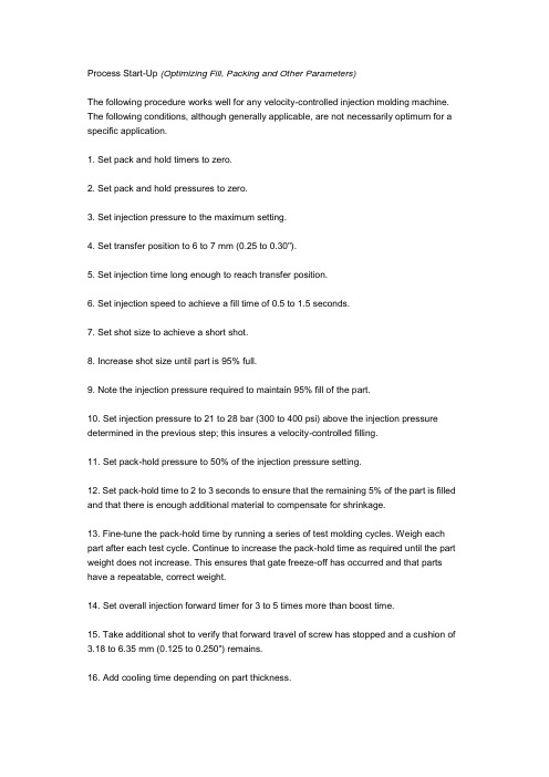
Process Start-Up (Optimizing Fill, Packing and Other Parameters)The following procedure works well for any velocity-controlled injection molding machine. The following conditions, although generally applicable, are not necessarily optimum for a specific application.1. Set pack and hold timers to zero.2. Set pack and hold pressures to zero.3. Set injection pressure to the maximum setting.4. Set transfer position to 6 to 7 mm (0.25 to 0.30").5. Set injection time long enough to reach transfer position.6. Set injection speed to achieve a fill time of 0.5 to 1.5 seconds.7. Set shot size to achieve a short shot.8. Increase shot size until part is 95% full.9. Note the injection pressure required to maintain 95% fill of the part.10. Set injection pressure to 21 to 28 bar (300 to 400 psi) above the injection pressure determined in the previous step; this insures a velocity-controlled filling.11. Set pack-hold pressure to 50% of the injection pressure setting.12. Set pack-hold time to 2 to 3 seconds to ensure that the remaining 5% of the part is filled and that there is enough additional material to compensate for shrinkage.13. Fine-tune the pack-hold time by running a series of test molding cycles. Weigh each part after each test cycle. Continue to increase the pack-hold time as required until the part weight does not increase. This ensures that gate freeze-off has occurred and that parts have a repeatable, correct weight.14. Set overall injection forward timer for 3 to 5 times more than boost time.15. Take additional shot to verify that forward travel of screw has stopped and a cushion of 3.18 to 6.35 mm (0.125 to 0.250") remains.16. Add cooling time depending on part thickness.17. Use of mold release is not recommended under any circumstances.。
- 1、下载文档前请自行甄别文档内容的完整性,平台不提供额外的编辑、内容补充、找答案等附加服务。
- 2、"仅部分预览"的文档,不可在线预览部分如存在完整性等问题,可反馈申请退款(可完整预览的文档不适用该条件!)。
- 3、如文档侵犯您的权益,请联系客服反馈,我们会尽快为您处理(人工客服工作时间:9:00-18:30)。
西南交通大学本科毕业设计论文翻译对注塑成型工艺参数优化的一般框架年级:2010级学号:20101476姓名:段威力专业:机械设计制造及其自动化指导老师:罗征志2014 年 3 月第1章前言成型条件和工艺参数在注塑成型工艺中起着重要角色。
模塑部分的质量包括:受力、热变形和残余应力,很大程度上受注塑工艺进程的条件状况影响。
成型条件也会影响注塑工艺的生产率、生产周期和资源消耗率。
成型条件与其他一些决定塑料产品的因素也有密切关系,如材料、零件的设计和加工等。
成型条件主要包括以下几个因素[1]:熔点、浇铸温度、填充时间、填料时间和填充压力。
指定模型零件的质量不仅取决于塑料材料特性同时取决于公益参数。
最佳工艺参数可以生产周期,提高产品质量。
在实际生产中,工艺参数的设定主要取决于工程师的经验。
这种方法不能一直确保工艺参数适当的价值。
由于塑料具有复杂的热塑性,设定工艺参数获得想要的产品质量是一个挑战。
最终,工艺参数往往从工具书中选取,随后通过反复试验法调整。
但是,事实上反复试验法耗时耗力。
对于分析法,为了得到合适的工艺参数需要陈列大量的数学方程[2]。
但是,由于复杂的注塑工艺,而方程中又应用了很多简化,这些方程并不能总是达到一个可靠的解决方案。
因此,很多研究者投入了大量精力研究注塑成型工艺参数的优化。
尽管目前有大量的文献注塑模工艺参数的优化,但是很多都是理论上的可行,没法投入到实际生产中。
因此,并没有对着这些优化方法的适用范围以及优缺点的系统地比较和评估。
优化方法的选择主要取决于每位作者的经验和主管选择。
甚至,分析现有有话方法的特点和适用范围都是很有意义的任务。
因此,寻求合适的一般框架简化注塑成型工艺参数设定是很有必要的。
第2章理论背景和现有注塑模型工艺参数优化的调查2.1 优化技术如果我们对现有的数值优化技术通过基于每次迭代后改进设计点的方式进行分类,有三种优化技术:非基于梯度的优化技术、基于梯度的优化技术和混合优化技术。
对他们的大致描述如下:非基于梯度的优化技术不需要目标函数f(x),具有可区分性,因为这类算法中没有f(x)的微分方程。
非基于梯度的优化技术的例子有自适应模拟退火法(adaptive simulatedannealing,)、胡克-纪夫斯直接搜索法(Hooke-Jeeves direct search)以及遗传算法(genetic algorithm, 以下简称GA)。
这些优化方法旨在寻求整体的最佳效果,但是需要大量的函数估计。
GA是一个比较著名的非基于梯度的优化技术。
它是一个模仿达尔文生物进化论的随机研究或者最优化算法基于梯度的优化技术现阶段主要通过功能梯度来定义调查方向。
在实际生产中,有很多的基于梯度的优化技术,例如广义简约梯度、共轭梯度、可行方向法、混合整数优化、序列线性规划、序列二次规划、和大卫-弗莱彻-鲍威尔法。
一般而言,基于梯度的优化技术可以给出一个快速集合,但是当变量增长是可能需要长时间运行。
基于梯度的优化技术也可以得到高非线性最优化问题的局部风险极值。
混合优化技术同时使用非基于梯度和梯度为基础的技术随后的结合,利用了双方的优点,同时减少单优化技术的缺点。
上文所述的这些优化技术都不在本文讨论范围内。
2.2 一般优化法在本文的优化方法,不论显性目标函数是否用公式表示出,均为术语的优化方法。
在基于模拟的优化中,目标函数通常以隐式方程的形式显示。
在模拟结果得出以前,目标函数的价值是不明显的。
如图1所示,有直接优化和基于元模型的两种优化方法来解决优化问题。
这两种优化方法的细节描述如下。
2.2.1直接优化法直接优化法是一种不需要明确的目标函数的优化方法。
非基于梯度的优化技术和基于梯度的优化技术都可以用来解决优化问题。
有时直接优化法结合了GA和其他优化方法。
众所周知,遗传算法更倾向于得到整体的极值。
但是这种方法需要大量的函数估计。
相反,基于梯度的优化方法更有效的确保得到局部极值。
如果这两种方法可以结合作为一个混合系统,便可以强化优势,消除劣势。
2.2.2 基于元模型的优化法元模型为基础的优化方法是一种方法,此方法的目标函数经常通过低阶多项式近似成具有可接受的精度的显式形式。
一旦元模型在数学上呈现具有最小误差的过程,最优化问题是很容易通过施加适当的优化技术解决。
相比于直接优化法,元模型为基础的优化方法应用更广泛。
常见的元模型是响应面法(RSM),人工神经网络(ANN),径向基函数(RBF),克里格(Kriging)和混合模式。
基于计算机工程设计和优化技术的元建模的审查,可以在辛普森等的调查[3]和Wang和Shan的成果[4]中找到。
这种优化方法有很多的优点,例如易于连接模拟程序,渲染整个设计空间的视图以及计算效率,对此Papalambros[5],Wang和Shan[4]以及Park和Dang[4]有提及。
2.3 注塑成型工艺参数优化的回顾在注塑成型工艺中直接优化法是不经常使用的。
这种方法需要模拟工具和优化代码的复杂结合。
部分学者已经研究过这种方法。
拉姆(Lam)等[7]提出了注塑模工艺条件优化GA/梯度混合法。
GA优化方法需要大量估值函数或者大量的模拟循环。
当许多计算机同时运行时并行计算可以减少模拟次数。
吴(Wu)等人采用了增强型的GA,简称分布多种群GA。
他们把优化算法、商业软件Moldflow与基于优势关系的约束处理技术以及主从分布式体系结构相结合[8]。
直接优化法也可以只应用基于梯度的优化方法。
当优化问题具有较低非线性是,这种方法运行更加迅速。
元模型优化方法广泛的应用在注塑模工艺中。
大多数普通的元模型优化方法应用广泛,如RSM,ANN,RBF和Kriging模型。
元模型优化方法的应用主要取依靠特别案例和研究人员的喜好。
以下是常见的优化方法在塑料注塑成型领域文献中出现。
2.3.1 响应面法(RSM)模型RSM模型是元模型技术之一,RSM模型中输入和输出之间的关系经常被表示为二次多项式的形式。
尽管这是传统的模型,但因为它的成熟完备和应用简单的特点仍然应用广泛。
在这种方法中正交阵列被应用作实验设计(Design of Experiment, DOE)。
RSM 是用来与GA优化算法结合使用,以减少翘曲,凹痕或收缩[9]。
实际上,我们可以使用任何优化技术来解决RSM模型方面的优化问题。
但是,大多数研究人员都应用GA,因为他们认为GA是整体通用的。
GA可以避免局部极值困扰。
其他作者采用RSM与基于梯度的优化技术相结合,或者他们应用RSM模型来预测工艺参数对模型零件的影响[11,14-17]。
2.3.2人工神经网络(ANN)模型人工神经网络是一种新兴的、用来模仿人类大脑一些基本功能的方法,因为它是一种功能强大工具,通过函数逼近预测的高非线性响应。
很多作者把ANN模型作为表示工艺参数和质量指数之间关系的预测模型。
Kwak等[18]、Yarlagadda和TeckKhong[19]以及Yarlagadda[20]指出,利用CAE分析提取数据学习的神经网络预测与实验结果吻合。
Kenig等[21]、Mok和Kwong[22]、Chen等[23]以及Altan[24]指出,神经网络模型能够精确地预测了产品质量,并且这种方法是可用的高效的质量标准(收缩、重量抗拉强度)预测工具。
人工神经网络被认为是一种可靠的模型,用以预测工艺参数和模型零件质量的关系。
基于这种模糊关系工艺参数优化可以就此解决。
人工神经网络更适合与GA结合应用。
Shen等[25]优化了注塑成型工艺参数中使用的人工神经网络和GA相结合的方法。
Chen等[26, 27]通过带有对ANN和GA的软计算对工艺参数优化,实现多输入多输出(multi-input multi-output, MIMO)和多输入单输出(multi-input single-output, MISO)的注塑模工艺。
Ozcelik 和Erzurumlu[28]比较了在应用方差分析(ANOVA),ANN和GA的注塑模工艺中的翘曲变形。
其他研究人员[29, 34]也在注塑模工艺中应用ANN和GA以提高模型零件的质量。
研究人员中总结出ANN和GA相结合的方法是可靠的方法。
然而,他们大多没有提到他们是怎样决定那些用以获得ANN模型的训练数据的实验的次数。
在这些研究中注塑参数从4到6变换不等,但是实验数目却在很大范围内波动((从27次[28]到252次[25])。
很显然,如果实验次数过高,模拟或物理实验的成本是非常高的。
2.3.3克里格(Kriging)模型克里格模型是一种元模型。
当工艺参数的数量适度时,它被认为是一个合适的确定性和高非线性的模型[3, 35]。
然而,这种方法对注塑模工艺领域的研究人员吸引力不高,因为相比RSM模型而言,它过于复杂或者说它不如ANN声誉好。
只有在很少的研究中应用到克里格模型。
Gao和Wang[36, 37]介绍了一种应用克里格模型有效的翘曲变形优化方法。
2.3.4 径向基函数(RBF)模型径向基函数模型也是一种常见的元模型,但是相比较其他元模型而言,它在工艺参数优化中的应用并不是十分广泛。
Li等人应用了径向基函数来优化注塑过程的包装更新问题[38]。
他们应用了基于梯度的优化方法(也就是序列二次规划)。
拉丁超立方体抽样技术被用于实验设计(DOE)。
这种技术给予设计者选择实验数量的自由。
虽然大量的研究是专门为了优化工艺参数,但现在还存在着一些相当大的问题。
现存的很多方法表明注塑成型工艺参数优化是相当复杂和多样的。
这些复杂程度由优化目标、模制部件的几何形状、材料和设计变量的数量决定。
此外,优化技术和优化方法的选择主要取决于经验和研究人员的主观选择。
在文献中,没有任何准则或一般化的优化方法使用,来达到优化注射成型工艺参数。
因此,本文提出基于模拟的注塑模优化方法以促进加快设计和优化进程。
第3章优化模型参数框架的提出3.1 使用直接数值优化模型的成型参数优化法使用直接数值优化模型来优化成型工艺参数的框架包括这样一个框架,它用于自动化模拟和基于直接模拟的优化的流程。
优化进程是基于直接数值优化方法的。
基于梯度和非基于梯度的优化方法都可以用来寻找最适宜的优化方法。
数值优化是指收敛完成最优化循环终止的搜索处理(最优方法已经建立),或者满足终值条件。
因为为大型和复杂的零件的CAE(计算机辅助工程)模拟的计算成本通常价格昂贵,一般终值条件预先设定为最大模拟数。
为了加速优化过程,使用直接数值优化模型的基于模拟的优化过程应该是自动的。
图2展示了使用直接数值优化模型的自动模拟框架。
该框架包括两个部分:优化控制器和CAE。
从CAE得到的模拟结果将会立刻被送至优化控制器。
随后,优化控制器在每次使用选择优化技术的迭代中评估结果并修改输入参数(设计变量)。