SY3200变频器说明书 V12.2
变频器说明书大全

红邦控制技术4.ABB变频器说明书ACS400ACS500ACS5105.AB变频器说明书1336PLUS II PowerFlex 4PowerFlex 406.AC Tech变频器说明书MC1000QC SCF7.BERGES变频器说明书ACM-D2/S2/S3ACM-COMPACT8.BONFIGLIOLI邦飞利变频器说明书ACT200/400ACU200/400VCB4009.CT变频器说明书Command er GP Unidrive SP Command er SE 10.Drivecon变频器说明书XS XT XR 11.EATON伊顿变频器说明书SVX9000SPX9000MVX900012.KEB科比变频器说明书F4-S F4-F F5-M 13.LG变频器说明书iS3iH3iG514、LUST路斯特变频器说明书CDD3000CDE/CDB3000CDS400015.Moeller金钟-默勒变频器说明书DV6-340DF5116.NORD诺德变频器说明书SK300ESK400ESK5xxE17.PDRIVE变频器说明书18.PE变频器说明书SD100SD250SD45019.RICH利佳/艾瑞克变频器说明书EI-MINIEI-450EI-450M20.SEW变频器说明书MOVITRAC -31C MOVIDRIV E-60B/61B MOVITRAC -0721.SIEI西威变频器说明书ARTDriveL ARTDriveG-EV22.TMT变频器说明书PLUS VTC E 23.VACON瓦控变频器说明书NX NXS NXL24.WEG变频器说明书CTW-04CFW-08CFW-0925.阿尔法ALPHA变频器说明书ALPHA2000G ALPHA2800ALPHA330026.艾默生(原华为)变频器说明书EV1000EV2000EV300027.爱得利变频器说明书APXG3ASASN28.爱迪生Adsen变频器说明书ADS-A29.安邦信AMBITION变频器说明书G9/P9V11G1130.安川YASKAWA变频器说明书G5G7E731.安普(AMPLE)变频器说明书AMP100032.百德福BEDFORD变频器说明书B500B80133.斑科Bantek变频器说明书BLDC34.宝德电气BODE变频器说明书BEM100BEM20035.葆德BALDOR变频器说明书10111236.贝西B&C变频器说明书BC-1000BC-2000BC-2300MX-eco/pro/multi-eco/multi-pro-1MX-eco/pro/m eco/multi-pro-237.传动之星(STAR@DRIVE)变频器说明书SD-5L-G/P/YSD-5L-S SD-7L38.创杰变频器说明书ACT-V6G/P/ZACT-M739.春日(KASUGA)变频器说明书KVFC40.丹佛斯(Danfoss)变频器说明书FC51FC100FC20041.德弗(DOVOL)变频器说明书DV300DV600ST50042.德莱尔变频器说明书DVA DVM DVS43.德力西变频器说明书CDI900044.德瑞斯(DIRISE)变频器说明书DRS1000-DRS2000DRS280045.东达变频器说明书TDS-F8TDS-V846.东洋(TOYO)变频器说明书VF61R VF6447.东元(TECO)变频器/伺服说明书7300EV7300CV7200MA48.东芝(TOSHIBA)变频器说明书VF-nC1VF-S9VF-S1149.方禾(FangH)变频器说明书TE280F66-B F66-C50.飞兆变频器说明书FG51.佛朗克(FRANCK)变频器说明书FRS2000FRB600052.佛斯特(FIRST)变频器说明书FST-500FST-550FST-60053.富凌(FULING)变频器说明书DZB60J DZB70B DZB200M54.富士(FUJI)变频器说明书FRN-G11S FRN-P11S E1S55.高士达(GOLDSTAR)变频器GS200L56.哥伦(GRET)变频器说明书GD-V557.格立特(GREAT)变频器说明书VF10VF11VF1558.海利普变频器说明书HOLIP-A/F/H/MHOLIP-C HOLIP-P59合康亿盛高压变频器说明书HIVERT通用HIVERT矢量60.泓筌变频器说明书HC1-A HC1-M61.鸿宝(HOSSONI)变频器说明书HB-G9/P9HB280-G HB280-P62.华科(HUANIC)变频器说明书HI3G/F HI9G/F63.华蓝(HLinverter)变频器说明书HL200064.汇川(INOVANCE)(默纳克NICE)变频器说明书MD300MD300A MD32065.汇菱(HUILING)变频器说明书H300066.基创变频器说明书E35067.吉纳变频器说明书MSC-3MFI-Case00/CaseA/CaseB68.加能变频器说明书ACmaster-H7IPC-MD IPC-DR69.佳川(JiaChuan)变频器说明书BP60JCRQ70.佳灵变频器说明书JB6C-T971.金肯(JINKEN)变频器说明书JK-G/P72.九德松益变频器说明书CT-200073.开拓变频器说明书KT-A6G/P74.凯迪华能变频器说明书CD200075.康沃(博世力士乐)变频器说明书S1G2G376.科陆变频器说明书CL1700CL2700CL370077.科姆龙变频器说明书KV1900KV200078.库马克变频器说明书CMK-30079.酷马(QMA)变频器说明书Q7000Q900080.乐邦变频器说明书LB60G LB90G81.乐星产电变频器说明书Starvert82.雷诺尔变频器说明书JJR1000JJR2000JJR500083.力普变频器说明书LP10084.菱科(LINGKE)变频器说明书LK600-G/P/ZSLK80085.隆兴变频器说明书LS200A LS600LS80086.路斯特(LUST)驱动器说明书AD系列CDD系列87.伦茨(Lenze)变频器说明书8200/82108220/8240823088.麦孚变频器说明书VFD-F540VCD100089.麦格米特变频器说明书MV300MV60090.美之源(MZY)变频器说明书MZY-M/Y/Z/T/L91.蒙德(MODROL)变频器说明书IMS-GF IMS-GL2IMS-GL392.米高变频器说明书Micovert2003Micovert34 0N93.明电舍(MEIDEN)变频器说明书VT230S VT230SE VT240S94.南方安华变频器说明书A100E100S10095.能士(NSA)变频器说明书NSA20NSA8096.宁茂(赫力)变频器说明书RM597.欧陆变频器/直流调速器说明书512C590+590P98.欧姆龙(OMRON)变频器说明书3G3JV3G3EV3G3FV99.欧瑞(HFinverter)(原惠丰)变频器说明书F2000-G F3000F1000-G100.派克汉尼汾(parker)变频器说明书AC650AC650V AC690+ 101.派尼尔(Pioneer)变频器说明书VF2100VF3000VF5000 102.普传(POWTRAN)变频器说明书PI97G PI7000/7100PI7500103.群倍(QUNBEI)变频器说明书QLP5000104.日搏变频器说明书RB600RB3000RB5000 105.日锋(RiFeng)变频器说明书RF200RF9000106.日虹变频器说明书CHRH-A CHRH-C CHRH-D 107.日立(HITACHI)变频器说明书SJ100L100SJ200 108.日普(RIPOW)变频器说明书RP3200109.日拓变频器说明书HL3000110.日业(SUNYE)变频器说明书SY3200111.荣信电力电子变频器说明书HVC112.瑞恩(RELIANCE)变频器说明书PSC4000/5000/DDS5000PSC7000VZ3000113.赛普(SAPPHIRE)变频器说明书SAP500G SAP300114.赛普变频器说明书SAP900G SAP300V115.三晶变频器说明书SAJ8000116.三肯(SANKEN)变频器说明书SAMCO-i SAMCO-vm05SAMCO-e117.三菱(MITSUBISHI)变频器说明书A500E500F500 118.三木(MIKI)变频器说明书V6119.三品(SANPIN)变频器说明书SKJ SPRQ-333120.三碁(SANCH)(三川)变频器说明书SA SE121.三星(SAMSUNG)变频器说明书MOSCON-E7MOSCON-F7MOSCON-F500122.森兰(SENLAN)变频器说明书SB50SB60/61SB61Z 123.山宇变频器说明书SY6000SJR2124.珊星变频器说明书F5000F6000125.深川变频器说明书SVF2000SVF3000126.神源(SYRUNS)变频器说明书SY4000SY5000127.施耐德变频器说明书ATV38ATV58-1ATV58-2 128.时代变频器说明书TVF1000TVF3000TVF5000 129.时运捷变频器说明书SuperBona-iF/iPDB-2100130.士林变频器说明书SH系列SS系列SB系列131.世通(EACON)变频器说明书EC1000EC3000EC5000 132.收获(Seoho)变频器说明书SOHO-VD SOHO-SMS133.思达(SD)变频器说明书JPSD3000-G/P/V/H134.斯德博(STOBER)变频器说明书FAS4000FDS4000MDS5000 135.四方变频器说明书C300C320E320 136.松下(PANASONIC)变频器说明书VF0VF0C VF-8Z 137.台安(TAIAN)变频器说明书E2N2V2138.台达(DELTA)变频器说明书VFD-A VFD-B VFD-F 139.台凌(TAILING)变频器说明书TL80TL100TL100H 140.腾龙变频器说明书VG3000-G/H141.天正变频器说明书TVFS9TVFG9/P9TVFG11 142.万谷(WANGU)变频器说明书VF2000143.威尔凯变频器说明书WKF WKS WKR5000 144.威科达变频器说明书V6145.威灵(WELLING)变频器说明书WELLING-G/P/F146.微能变频器说明书WIN-VB WIN-9G WIN-9F 147.韦尔变频器说明书AC30G/P/W/H148.伟创(VEICH)变频器说明书AC20AC32AC60 149.沃森(VicRuns)变频器说明书VSI9000150.西驰变频器说明书CFC1000CFC4000151.西尔康变频器说明书H3000152.西林变频器说明书EH600A EH600M EH600W 153.西门子(SIEMENS)变频器说明书MM410MM420MM430154.现代(HYUNDAI)变频器说明书N50N100N300 155.晓磊(CHXL)变频器说明书LEI2000LEI2005LEI3000 156.信捷(XINJE)变频器说明书V5/F5157.星河(XINHE)变频器说明书SD-5L158.亚泰(YT)变频器说明书YTD-G160.阳冈电子变频器说明书G1/H1/P1E1S1 161.依尔通(Emotron)变频器说明书FDU VFX VSA 162.依托(ESTAR)变频器说明书EG/EF163.亿森变频器说明书参数表164.易能变频器说明书EDS700EDS2860165.易驱变频器说明书ED2003ED2800ED3000 166.意科(IECCO)变频器说明书SINUS-N167.英泰(Invertek DRIVES)变频器说明书OptidrivePlus 3GV OptidrivePlus3GVCompactOptidriveVTC168.英威腾(INVT)变频器说明书CHV100CHV190CHF100 169.鹰垦(INK)变频器说明书SLX170.优利康变频器说明书YD3000YD5000171.尤尼康(UNICON)(原北京兰海)变频器说明书低速大扭矩无码盘有码盘172.誉强(YUQIANG)变频器说明书YQ3000-M YQ3000-A YQ3000-G 173.远川(YCDZ)变频器说明书YC-G YC-P174.正频(JPS)变频器说明书PDS PDA/H/E175.正泰(CHINT)变频器说明书NI01176.正弦(SINEE)变频器说明书SINE300SINE303SINE307 177.正阳(Zhengyang)变频器说明书ZY29/31/98ZY-812178.中源(ZYDL)变频器说明书ZY-G800ZY-G800E ZY-A900 179.中远变频器说明书MF6MF5/20MF30 180.珠峰变频器说明书DLT-G11/P11/Z181.住友(SUMITOMO)变频器说明书HF320SF320HF430 182.紫日(CHZIRI)变频器说明书ZVF7ZVF9ZVF9V 183.南海华腾(V-T)变频器说明书V5-H E5-P V6-HACS600ACS800ACS1000PowerFlex 400PowerFlex 70PowerFlex 700SE1SW1SYN10S/T SPL200/400VF5100HG VF51RG VFDBVF61CVF61VF64VFK1/VFN1GVX9000F5-M/S iS5iHSK530E SK700E SK750ESD700EI-500EI-550EI-600EI-700EI-7001EI-8001EI Super NMOVIRET-315/328/355/380/3150IP55 PLUS IP55 E CFW-10CFW-11EV3100EV3500TD900TD1000TD2000TD3000TD3100MSE11Z9/Z11F7J7V7PC3P5/PC514ro/multi-co/multi-pro-2FC300VLT2000VLT2800VLT2900VLT3000VLT5000 HL2000DV1000DRS30007200GA7300PA7200GSVF-A5VF-A7VF-AS1DZB300BF1S FRN-FVR-E11SMini/C1SHB280-ZMD330ME280NICE3000IPC-RF9300Vector690+590C3G3HV3G3MV3G3RVF1500-GPI7600/78PI766000SJ300SJ300-EL L200L300P VZ7000MF/MS ES/ET/EF IHF/IPF SHF/SPFS500A700E700F700D700 SB70SB100SB200BT40ATV61ATV68-1ATV68-2ATV68-3SDS4000E350E380E520H320M1X M2XVF100DV700/707SV300N310S310EV300VFD-G VFD-M VFD-S VFD-VWIN-9I WIN-9LAC61-Z AC62-LEH600ZMM4406RA706SE70J300TOPVERT TOPVERT TOPVERTVSC CDX CDU MSF ED300S ED3100Optidrive E OptidriveE1OptidriveE2OptidriveMEMA 4XSINE308SINE309 ZY-P800ZVF11VFN2TD3200TD3300。
SY3200变频器说明书 V12.2

6-8、保护参数……………………………………………………………… ……… …… … 47 6-9、其它功能…………………………………………………………… ………………… 51 6-10、RS-485 控制……………………………………………………………………………53
7、排除故障 ………………………………………………………………………………………54
如果上述任一检查项目不满足,请和本公司或代理商联系。
1-1-2、检查铭牌数据
铭牌数据 以型号 SY3200- G022T4 为例
型号规格 输入规格 输出规格 机器编号
MODEL:SY3200-G022 T4 INPUT:AC 3PH
1.5KW 50/60Hz 45A
380V ±15%
OUTPUT:AC 3PH 0-380V 0-300HZ SER NO:
本章叙述 SY3200 系列变频器在安装时所必需了解的构造、设置环境及空间。 2-1、卸下和重新装上前盖
一般安装,不需要取下前盖及操作器。操作器与内部电路有电缆相连接,装卸时务必小心。先 拔下电缆,再取下操作器及面板,否则可能使插头拉坏。
2-2、取下和重新装上数字操作器
5
按照下述方法取下和重新装上数字操作器: 取下数字操作器。 按向下方向按压数字操作器的锁定扣子,可把数字操作器从前盖上取出。 重新装上数字操作器。 把数字操作器压入面板键盘框上,锁定扣子会自动锁住数字操作器。
3、接线 ……………………………………………………………………………………………7
3-1、外围设备和任选件的接线………………………………………………………………9 3-2、连接图………………………………………………………………………………………10 3-3、主回路的接线………………………………………………………………………………11 3-4、接地…………………………………………………………………………………………15 3-5、控制电路的接线……………………………………………………………………………15 3-6、接线检查……………………………………………………………………………………17
SV-3200中控用户手册

多媒体中央控制系统(SV-3200)安装使用手册SV-3200中控系统安装使用手册2003 [09]目录一、产品简介 (4)二、设备包装说明 (5)三、主控机前面板示意图 (5)四、主控机后面板示意图 (6)五、系统主机、操作面板、电脑的连接 (6)六、应用设备连接示意图 (6)七、红外发射棒的连接 (7)八、投影机控制线连接: (7)九、电动屏幕接线图 (7)十、操作面板使用说明 (8)1、43键面板 (8)十一、多媒体控制软件的安装 (10)十二、红外控制器的使用 (11)十三、设备红外遥控器代码的学习和录入 (11)十四、主控机系统各项参数 (12)十五、常见故障排除 (14)1、通过面板“系统开”无法开机 (14)2、面板控制不灵 (14)3、有些设备红外遥控不灵 (14)4、电脑软件无法控制 (14)5、红外学习不成功或显示成功却不能遥控 (15)十六、本手册说明 (15)前言感谢您购买和使用本公司的产品,在使用本机前请细阅这本用户手册以便能正确使用并且请妥善保存这本手册万一有不了解或故障时这本手册会带给您很大的帮助。
可编程多媒体中央控制系统是最新开发的智能化产品,是通过面板控制及计算机软件控制的电教产品。
该系统的所具有的特点:控制主机是SV-3200(SVS)电教产品的经典之作,一体化的控制结构、全双向控制方式、美观的控制面板,同时支持状态反馈,一目了然。
它集成了3路电源管理、4选2路视/音频切换矩阵、4路红外遥控、红外遥控自学习、3X2VGA信号切换、全数码声音控制、可编程串行通讯等功能模块。
其强大的红外学习功能对所有红外码都能有效学习,遥控灵敏;其灵活的开关机编程功能使得使用非常灵活方便。
它有较强的接入兼容性,可通过按键控制面板进行控制,也可以通过软件控制,还可以连接AMX、快思聪等设备。
为确保设备可靠使用及人员的安全,请在安装、使用和维护时,请遵守以下事项:1、为确保操作安全,应确保电源线接地良好,务必将随机提供的三相插头插入地线有效的标准三脚电源插座,确保设备的输入电源为220V50HZ的交流电。
3200系列公共驱动包装传输系统说明书

3200 SERIES COMMON DRIVE PACKAGESpecial Capabilities Specification Sheet 975CottonwoodAve.,POBox20,Hartland,Wisconsin53029-0020,USA||***************COMMON DRIVE CONVEYOR SETUPUp to (4) conveyors can be coupled together and driven from a single gearmotor.• Conveyors move at same relative belt speed.• Creates single lanes for handling parts.• Wide parts or pallets can be carried by each conveyor to allow access from below.• Conveyors can be of different widths and lengths.Uses Standard 3200 Series End Drive Conveyors• Aluminum Extruded Frame with T-slot Construction• Sealed Ball Bearings• V-guided and Non-V-guided Belt Compatible• Rack and Pinion Belt Tensioning• Conveyor Widths: 3.75" to 48" wide• Conveyor Lengths: End Drive = 3' to 40' long• 3" diameter Drive Pulley turns approximately 9.7" of Belt per revolution• Belt Speeds: up to 421 ft/minSee Product Engineering Manual or for details.Common Drive Specifications• Drive up to (4) Conveyors from a Single Drive Gearmotor• Fixed Conveyor Locations• Load Capacity: Contact Factory for Details• Compatible with all Standard End Drive Gearmotor Mounting Packages• Includes Aluminum Extruded Conveyor Tie Bar Assembly with Belt Return Roller• Includes Common Drive Couplings and Guarding• Multiple Conveyor Spacing Options• 5.75" Belt Edge to Belt Edge• 8" to 24" Belt Edge to Belt EdgeW +1.2.06[1/4-20 T -N U T SC o m p a t i b l e w i t h a l lProfiles:• All 3200 Series profiles are applicable.See Product Engineering Manual or for details. •Belting:• All 3200 Series belting is applicable.• Finger Splice is preferred, plastic and metal clipper splices are available.See Product Engineering Manual or for details. •Mounting Packages & Gearmotors:• All 3200 Series mounting packages and gearmotors are applicable.See Product Engineering Manual or for details. •Support Stands:• All 3200 Series support stands are applicable.See Product Engineering Manual or for details. •EXPRESS INQUIRY FORM: GENERAL INFORMATIONAlong with completing the Express Inquiry form below, please complete the specific 3200 Series Common Drive Conveyor application questions on the next page to the best of your ability.ContactTechnicalSalesat1-800-259-1510(Press3)***************************************************.CONTACT INFORMATIONCompany: ____________________________________________________________ Date: ____________________ Name: _________________________________________________________________________________________ Phone: __________________________ Fax: ________________________ E-Mail: _________________________ Address: _______________________________________________________________________________________ City: ______________________________________ State: ____________ Zip: ___________________________PRODUCTDescription/Material: ______________________________________________________________________________ Dimensions:_____________________________________________________________________________________ Weight: ____________________________________ Total Weight to be Placed on Conveyor: ____________________ Temperature: ________________________________ Leading Edge Dimension: ______________________________ENVIRONMENTChemicals or Fluids Present: ________________________________________________________________________ Unusual Ambient Temperature Conditions: ______________________________________________________________ Other Concerns: __________________________________________________________________________________Complete individual conveyor specifications on page 6.EXPRESS INQUIRY FORM: GENERAL INFORMATIONPage may need to be copied to communicate multiple conveyorsFAX COMPLETED FORMS TO 800.369.2440 or 262.367.5827BELT SPEED CALCULATORHow to calculate minimum conveyor belt speed:(Part rate in parts per minute) x (part size in inches)12Example (30 parts per minute) x (6" dia. part) = 180 = 15 ft/min. Minimum Belt Speed12 12How to calculate conveyor belt speed incorporating a product spacing:(Part rate in parts per minute) x (desired part spacing in inches + part size in inches)12Example (30 parts per minute) x (6" dia part + 12" spacing between parts) = (30) x (18) = 540 = 45 ft/min. Belt Speed12 12 12Please highlight the conveyor, dimensions, belt flow and motor positions required.Belt Edge to Belt Edge Options: • 5.75" (146)• 8" to 24" (203-610)。
3200系列侧挂90度转速驱动包 для重载减速机械臂安装、维护与配件手册说明书
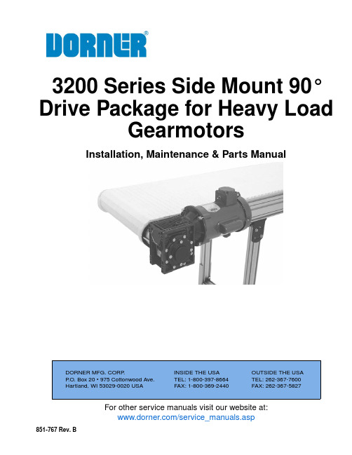
For other service manuals visit our website at:/service_manuals.aspDORNER MFG. CORP .INSIDE THE USA OUTSIDE THE USA P .O. Box 20 • 975 Cottonwood Ave.TEL: 1-800-397-8664TEL: 262-367-7600Hartland, WI 53029-0020 USA FAX: 1-800-369-2440FAX: 262-367-5827851-767 Rev. B3200 Series Side Mount 90° Drive Package for Heavy LoadGearmotorsInstallation, Maintenance & Parts ManualDorner Mfg. Corp.2851-767 Rev. B3200 Series Side Mount 90° Drive Package for Heavy Load GearmotorsTable of ContentsIntroduction......................................................................... 2Warnings - General Safety.................................................. 3Product Description............................................................. 4Specifications...................................................................... 4Gearmotor Mounting Package Models:........................... 4Table 1: 60 Hz Gearmotor Specifications........................ 4Table 2: Belt Speeds for Fixed Speed90° 60 Hz Gearmotors..................................................... 5Table 3: Belt Speeds for Variable Speed90° 60 Hz Gearmotors..................................................... 5Table 4: Belt Speeds for Fixed Speed90° 60 Hz VFD Gearmotors............................................ 5Table 5: 50 Hz Gearmotor Specifications........................ 6Table 6: Belt Speeds for Fixed Speed90° 50 Hz Gearmotors..................................................... 6Table 7: Belt Speeds for VFD Variable Speed90° 50 Hz Gearmotors (6)Installation............................................................................ 7Required Tools................................................................. 7Mounting.......................................................................... 7Preventive Maintenance and Adjustment............................ 9Required Tools................................................................. 9Gear Reducer Replacement.............................................. 9Motor Replacement........................................................ 11Notes.................................................................................. 12Service Parts....................................................................... 133200 Series Side Mount Drive Packagefor Heavy Load 60 Hz 90° Gearmotors.......................... 133200 Series Side Mount Drive Packagefor Heavy Load 50 Hz 90° Gearmotors.......................... 14Heavy Load 90° Gearmotors.......................................... 1560 Hz Gearmotors....................................................... 1550 Hz Gearmotors....................................................... 15Return Policy. (16)IntroductionUpon receipt of shipment:•Compare shipment with packing slip. Contact factory regarding discrepancies.•Inspect packages for shipping damage. Contact carrier regarding damage.•Accessories may be shipped loose. See accessory instruc-tions for installation.Dorner 3200 Series conveyors have patents pending.Dorner’s Limited Warranty applies.Dorner reserves the right to make changes at any time without notice or obligation.Dorner has convenient, pre −configured kits of Key Service Parts for all conveyor products. These time saving kits are easy to order, designed for fast installation, and guarantee you will have what you need when you need it. Key Partsand Kits are marked in the Service Parts section of this manual with the Performance Parts Kits logo.IMPORTANTSome illustrations may show guards removed. DO NOT operate equipment without guards.851-767 Rev. B3Dorner Mfg. Corp.3200 Series Side Mount 90° Drive Package for Heavy Load GearmotorsWarnings - General SafetyA WARNINGThe safety alert symbol, black triangle with white exclamation, is used to alert you to potential personal injury hazards.Climbing, sitting, walking or riding on conveyor will cause severe injury.KEEP OFF CONVEYORS.DO NOT OPERATE CONVEYORS IN AN EXPLOSIVE ENVIRONMENT.A WARNINGExposed moving parts can cause severe injury.LOCK OUT POWER before removing guards or performing maintenance.AWARNINGGearmotors may be HOT.DO NOT TOUCH Gearmotors.A WARNINGExposed moving parts can cause severe injury.REPLACE ALL GUARDS BEFORE RUNNING CONVEYOR.A WARNINGDorner cannot control the physicalinstallation and application of conveyors. Taking protective measures is the responsibility of the user.When conveyors are used in conjunction with other equipment or as part of a multiple conveyor system, CHECK FOR POTENTIAL PINCH POINTS and other mechanical hazards before system start-up.Dorner Mfg. Corp.4851-767 Rev. B3200 Series Side Mount 90° Drive Package for Heavy Load GearmotorsProduct DescriptionRefer to Figure 1 for typical conveyor components.Figure 1SpecificationsGearmotor Mounting Package Models:Example:Table 1: 60 Hz Gearmotor Specifications1Conveyor2Gearmotor Mounting Package 3Gearmotor Assembly 4Spider Web Bushing5Shaft Coupling Half, Three Jaw 6Coupling Half, Three Jaw 7Key, Coupling 8Shaft9Key, Shaft172458963ItemHeavy Load GearmotorSingle- Phase Three Phase VFD Variable Speed DC Variable Speed Output Power0.5 hp (0.37 kw)0.5 hp (0.37 kw) - 2.0 hp (1.5 Kw)0.5 hp (0.37 kw) - 0.75 hp (0.56 Kw)Input Voltage 115VAC 208 - 230/460 VAC 230/460 VAC 90VDCInput Frequency 60Hz 6 - 60Hz N/AInput Current (Amperes)8 2 - 6.2 for 230V & 1 - 3.1 for 460V 1.6 - 5 for 230V & 0.8 - 2.5 for 460V5 - 7.5Gearmotor Ratios 7.5:1, 10:1, 15:1, 20:1, 25:1, 30:1, 40:1, 50:1, 60:1, 80:1, 100:1Frame Size 56C 56C for 0.5 hp - 1 hp & 145TC for 1.5 hp - 2 hp 56CMotor T ypeT otally enclosed, Fan cooledSpecifications Table 2: Belt Speeds for Fixed Speed 90° 60 Hz GearmotorsHeavy Load Gearmotors Belt Speed for Standard Belts Belt Speed for High Strength Belts Part Number RPM In-lb N-m Ft/min M/min Ft/min M/min 32M100HH4(vp)FN1791310317 5.221 6.4 32M080HH4(vp)FN228339422 6.7288.5 32M060HH4(vp)FN2967976298.83611.0 32M050HH423FN3812051363811.64814.6 32M040HH423FN4310231154313.15416.4 32M030HH423FN5812161375817.77322.2 32M025HH423FN7010681217021.38826.8 32M020HH423FN8611831348626.210832.9 32M015HH423FN11590910311535.114544.2 32M010HH423FN1736367217352.721866.4 32M008HH423FN2304825423070.129088.3 (vp) = voltage and phase11 = 115 V, 1-phase23 = 208 – 230/460 V, 3-phaseTable 3: Belt Speeds for Variable Speed 90° 60 Hz GearmotorsStandard Load Gearmotors Belt Speed for Standard Belts Belt Speed for High Strength Belts Part Number RPM In-lb N-m Ft/min M/min Ft/min M/min 32M100HHD9DEN2563071 2.5 - 25.00.8 - 7.7 3.1 - 31.00.9 - 9.4 32M080HHD9DEN3157464 3.1 - 31.00.9 - 9.4 3.9 - 39.0 1.2 - 11.8 32M060HHD9DEN4246853 4.2 - 42.0 1.3 - 12.8 5.3 - 53.0 1.6 - 16.1 32M050HHD9DEN5062470 5.0 - 50.0 1.5 - 15.2 6.3 - 63.0 1.9 - 19.2 32M040HHD9DEN6352960 6.3 - 63.0 1.9 - 19.27.9 - 79.0 2.4 - 24.0 Table 4: Belt Speeds for Fixed Speed 90° 60 Hz VFD GearmotorsHeavy Load Gearmotors Belt Speed for Standard Belts Belt Speed for High Strength Belts Part Number RPM In-lb N-m Ft/min M/min Ft/min M/min 32M100HH423EN17913103 1.7 - 17.00.5 - 5.2 2.1 - 21.50.1- 1.5 32M080HH423EN2283394 2.2 - 22.00.7 - 6.7 2.7 - 27.80.8 - 8.4 32M060HH423EN2967976 2.9 - 29.00.9 - 8.8 3.6 - 36.0 1.0 - 11.1 32M050HH423EN381205136 3.8 - 38.0 1.2 - 11.6 4.8 - 48.0 1.4 - 14.6 32M040HH423EN431023115 4.3 - 43.0 1.3 - 13.1 5.4 - 54.3 1.6 - 16.5 32M030HH423EN581216137 5.8 - 58.0 1.8 - 17.77.3 - 73.0 2.2 - 22.3 32M025HH423EN7010681217.0 - 70.0 2.1 - 21.38.8 - 83.4 2.6 - 26.9 32M020HH423EN8611831348.6 - 86.0 2.6 - 26.210.8 - 108.7 3.2 - 33.1 32M015HH423EN11590910311.5 - 115.0 3.5 - 35.114.5 - 145.3 4.4 - 44.2 32M010HH423EN1766367217.3 - 173.0 5.3 - 52.722.2 - 222.5 6.7 - 67.8 32M008HH423EN3304825433.0 - 330.010.5 - 100.641.7 - 417.212.7 - 127.13200 Series Side Mount 90° Drive Package for Heavy Load Gearmotors851-767 Rev. B5Dorner Mfg. Corp.Dorner Mfg. Corp.6851-767 Rev. B3200 Series Side Mount 90° Drive Package for Heavy Load GearmotorsSpecificationsTable 5: 50 Hz Gearmotor SpecificationsTable 6: Belt Speeds for Fixed Speed 90° 50 Hz GearmotorsTable 7: Belt Speeds for VFD Variable Speed 90° 50 Hz GearmotorsItemHeavy Load GearmotorThree Phase VFD Variable Speed Output Power 0.37 to 1.5 kw 0.37 to 1.5 kw Input Voltage 230 / 400 V 230 / 400 V Input Frequency50 Hz 25 to 63 HzInput Current (Amps)see tables 6 & 7Gearmotor Ratios 7.5:1, 10:1, 15:1, 20:1, 30:1, 40:1, 50:1, 80:1, 100:1Frame Size 90B5, 90B5, 90B5, 90B5, 90B5, 80B5, 80B5, 71B5, 71B5Motor T ypeTotally enclosed, Fan cooledPart Number Ratio RPM M/min Standard BeltsM/minHigh Strength BeltsKw Amps N-m 52Z100HH423FN 10014 4.3 5.30.37 2.1/1.212952Z080HH423FN 8017.5 5.3 6.70.37 2.1/1.211552Z050HH423FN 50288.510.70.55 2.6/1.512452Z040HH423FN 403510.713.40.55 2.6/1.510552Z030HH423FN 304714.218.1 1.1 4.7/2.716752Z020HH423FN 207021.326.9 1.1 4.7/2.712252Z015HH423FN 159328.435.8 1.5 6.1/3.512752Z010HH423FN 1014042.753.9 1.5 6.1/3.58952Z008HH423FN7.518756.972.01.56.1/3.568Part Number Ratio RPM M/min Standard BeltsM/minHigh Strength BeltsKw Amps N-m 52Z100HH423EN 1007 to 18 2 to 5 2 to 70.37 2.1/1.212952Z080HH423EN 809 to 22 3 to 7 3 to 80.37 2.1/1.211552Z050HH423EN 5014 to 35 4 to 11 5 to 130.55 2.6/1.512452Z040HH423EN 4018 to 44 5 to 13 6 to 160.55 2.6/1.510552Z030HH423EN 3023 to 597 to 188 to 22 1.1 4.7/2.716752Z020HH423EN 2035 to 8811 to 2713 to 33 1.1 4.7/2.712252Z015HH423EN 1547 to 11814 to 3618 to 45 1.5 6.1/3.512752Z010HH423EN 1070 to 17621 to 5426 to 67 1.5 6.1/3.58952Z008HH423EN7.593 to 23528 to 7235 to 901.56.1/3.568NOTEFor belt speed other than those listed, contact factory for details.851-767 Rev. B7Dorner Mfg. Corp.3200 Series Side Mount 90° Drive Package for Heavy Load GearmotorsInstallationRequired Tools•Hex key wrenches:2 mm, 2.5 mm,3 mm, 5 mm •Torque wrenchMountingInstallation Component List:1.Typical components (Figure 2).Figure 2Figure 32.Install spider bushing (Figure 4,item 1) in three jaw coupling (Figure 4,item 2).Figure 43.Verify that three jaw coupling half (Figure 4,item 3) is flush with and against flange (Figure 4,item 4) of shaft (Figure 4,item 5). Loosen set screw on coupling half and push onto shaft until flush, if necessary.4.Making sure key (Figure 4,item 6) is installed in slot in gear reducer output shaft assembly (Figure 4,item 5), install output shaft into gearmotor assembly. Raise gearmotor assembly and install three jaw coupling end of output shaft onto three jaw coupling (Figure 4,item 2).A WARNINGExposed moving parts can cause severe injury.LOCK OUT POWER before removing guards or performing maintenance.1Conveyor2Gearmotor Mounting Package 3Gearmotor Assembly 4Spider Web Bushing5Shaft Coupling Half, Three Jaw 6Coupling Half, Three Jaw 7Key, Coupling 8Shaft9Key, Shaft172458963NOTEGearmotor may be operated in positions 1, 3 or 4 (Figure 3).132645InstallationNOTEBe sure four spacers on mounting screws(Figure 5,item2) are in place next toconveyor before installing gearmotor.5.Slide and pivot gearmotor and gearmotor mountingbracket (Figure 5,item1) onto four mounting screws(Figure 5,item2) (through slots in gearmotor bracket).22122Figure56.Tighten four mounting screws (Figure 5,item2).3200 Series Side Mount 90° Drive Package for Heavy Load GearmotorsDorner Mfg. Corp.8851-767 Rev. B851-767 Rev. B9Dorner Mfg. Corp.3200 Series Side Mount 90° Drive Package for Heavy Load GearmotorsPreventive Maintenance and AdjustmentRequired Tools•Hex-key wrenches:2 mm, 2.5 mm,3 mm, 5 mm•Adjustable wrench (for hexagon head screws)•Straight edge •Torque wrenchGear Reducer Replacement1.Loosen the four (4) mounting screws (Figure 6,item 1).Figure 62.Rotate gearmotor assembly and remove gearmotor mounting bracket (Figure 6,item 2) and entire gearmotor assembly from conveyor.3.Remove gear reducer output shaft assembly (Figure 7,item 1), and key (Figure 7,item 2) from coupler housing (Figure 7,item 3).Figure 74.Remove the four (4) coupler housing screws (Figure 8,item 1) and remove the mounting bracket and coupler housing (Figure 8,item 2) as an assembly.Figure 85.Remove four screws (Figure 9,item 1). Detach motor (Figure 9,item 2) from gear reducer (Figure 9,item 3), making note of position of switch (Figure 9,item 4) for reassembly. Retain motor output shaft key (Figure 9,item 5).Figure 9A WARNINGExposed moving parts can cause severe injury.LOCK OUT POWER before removing guards or performing maintenance.A WARNINGGearmotor can rotate and fall off, causing injury.Support the gearmotor prior to removal.2111112311232451Dorner Mfg. Corp.10851-767 Rev. B3200 Series Side Mount 90° Drive Package for Heavy Load GearmotorsPreventive Maintenance and Adjustment6.Inspect gear reducer output shaft assembly for wear or damage. If necessary, loosen set screw (Figure 10,item 1) and remove 3 jaw coupling (Figure 10,item 2) from gear reducer output shaft (Figure 10,item 3).Figure 107.Remove and retain key (Figure 10,item 4) from shaft. Install new components for shaft reverse of removal. Tighten set screw (Figure 10,item 1) to 35 in-lb (4 N −m).Figure 118.With key (Figure 12,item 1) in keyway, slide motor (Figure 12,item 2) and gear reducer (Figure12,item 3) together, noting where position of switch (Figure 12,item 4) will be during installation on conveyor.Figure 129.Install screws (Figure 12,item 5) and tighten to 65 in −lbs (7.3 N −m).10.Install coupler housing (Figure 13,item 1) to gearreducer (Figure 13,item 2) and tighten screws (Figure 13,item 3).Figure 13plete steps 2 through 6 of “Mounting” sectionbeginning on page 7.NOTEIf replacing the 3 jaw coupling on conveyor or output shaft, the coupling hub surface (Figure 10,item 1) should be flush to both output shaft (Figure 10,item 2).IMPORTANTBe extremely careful when coupling motor to gear reducer. Avoid misalignment and forcing the connection causing possible permanent gear reducer seal damage.431212324153312851-767 Rev. B11Dorner Mfg. Corp.3200 Series Side Mount 90° Drive Package for Heavy Load GearmotorsPreventive Maintenance and AdjustmentMotor Replacement1.For single phase motor, unplug power cord from outlet.2.For three phase and VFD variable speed motor:a.Loosen terminal box screws (Figure 14,item 1) and remove cover (Figure 14,item 2).Figure 14b.Record wire colors on terminals 1, 2 and 3. Loosen wire nuts and remove wires 1, 2 and 3.c.Loosen cord grip and remove cord.3.For DC variable speed motor, unplug motor cord at disconnect (Figure 15,item 1).Figure 154.Remove four (4) screws (Figure 16,item 1). Detach motor (Figure 16,item 2) from gear reducer (Figure 16,item 3). Retain motor output shaft key (Figure 16,item 4).Figure 165.With key (Figure 16,item 4) in keyway, slide motor (Figure 16,item 2) and gear reducer (Figure16,item 3) together, noting where position of switch (Figure 16,item 5) will be during installation on conveyor.6.Install screws (Figure 16,item 1) and tighten to 65 in −lbs (7.3 N −m).7.Replace wiring:•For a single phase motor, reverse step 1.•For a three phase or VFD variable speed motor, reverse step 2.•For a DC variable speed motor, reverse step 3.A WARNINGExposed moving parts can cause severe injury.LOCK OUT POWER before removing guards or performing maintenance.Hazardous voltage will cause severe injury or death.LOCK OUT POWER BEFORE WIRING.112IMPORTANTBe extremely careful when coupling motor to gear reducer. Avoid misalignment and forcing the connection causing possible permanent gear reducer seal damage.132541Notes3200 Series Side Mount 90° Drive Package for Heavy Load GearmotorsDorner Mfg. Corp.12851-767 Rev. B851-767 Rev. B13Dorner Mfg. Corp.3200 Series Side Mount 90° Drive Package for Heavy Load GearmotorsService Parts3200 Series Side Mount Drive Package for Heavy Load 60 Hz 90° GearmotorsNOTEFor replacement parts other than those shown in this section, contact an authorized Dorner Service Center or the factory. Key Service Parts and Kits are identified by the Performance Parts Kits logo . Dorner recommends keeping these parts on hand.2Item PartNumber Description1807-1167Gearhead Cover 2807-1328 3 Jaw Rubber Spider 3807-1683 3 Jaw Coupling 4912-111Square Key 5350551Standoff Spacer6350552Mount Plate for Standard Belts 350550Mount Plate for High Strength Belts 351047Mount Plate for Nose Bar T ail 7352312Mount T ube8352313Output Shaft 9450195Cam Spacer10639971M Drop-In T ee Bar for T -Slot Frames Only 11920625M Socket Head Screw,M6-1.00 x 25 mm for T -Slot Frame 807-2344Self-Drilling Hex Head Screw,1/4-20 x 1.25" for Smart Slot Frames 129208100M Socket Head Screw, M8-1.25 x 100 mm 13950816M Low Head Cap Screw, M8-1.25 x 16 mm 14950835M Low Head Cap Screw, M8-1.25 x 35 mm15980618MSquare Key, 6 mm x 18 mmItem Part NumberDescriptionDorner Mfg. Corp.14851-767 Rev. B3200 Series Side Mount 90° Drive Package for Heavy Load GearmotorsService Parts3200 Series Side Mount Drive Package for Heavy Load 50 Hz 90° Gearmotors2Item PartNumber Description1807-1167Gearhead Cover 2807-1328 3 Jaw Rubber Spider 3807-1588O-Ring4807-1683 3 Jaw Coupling, 20 mm 807-2239 3 Jaw Coupling, 25 mm 5980850M Square Key 6350551Standoff Spacer7350552Mount Plate for Standard Belts 350550Mount Plate for High Strength Belts 351047Mount Plate for Nose Bar Tail8352312Mount T ube 9350321Output Shaft 10450195Cam Spacer11639971M Drop-In T ee Bar for T -Slot Frames Only 12920625M Socket Head Screw,M6-1.00 x 25 mm for T -Slot Frames 807-2344Self-Drilling Hex Head Screw,1/4-20 x 1.25" for Smart Slot Frames 139208100M Socket Head Screw, M8-1.25 x 100 mm 14950816M Low Head Cap Screw, M8-1.25 x 16 mm 15950835MLow Head Cap Screw, M8-1.25 x 35 mmItem Part NumberDescription851-767 Rev. B15Dorner Mfg. Corp.3200 Series Side Mount 90° Drive Package for Heavy Load GearmotorsService PartsHeavy Load 90° Gearmotors60 Hz Gearmotors50 Hz Gearmotors21Item Part No.Description162MH411FN Motor, 0.5hp (0.37Kw), 115 Volts, 60Hz, 1-Phase62MH411FR Motor, 0.5hp (0.37Kw), 115 Volts, 60 Hz, 1-Phase with Reversing62MH423Motor, 0.5hp (0.37Kw), 208-230/460 Volts, 60 Hz, 3-Phase32MS423EN Motor, 0.5hp (0.37Kw), 230/460 Volts, 3-Phase VFD62MHD9DEN Motor, 0.5hp (0.37Kw), 90 Volts DC 32MHD9DEN Motor, 0.75hp (0.56Kw), 90 Volts DC 32MHH423FN10Motor, 1.0hp (0.75Kw), 208-230/460 Volts, 60 Hz, 3-Phase32MHH423EN10Motor, 1.0hp (0.75Kw), 230/460 Volts, 60 Hz, 3-Phase VFD 32MHH423FN15Motor, 1.5hp (1.1Kw), 208-230/460 Volts, 60 Hz, 3-Phase32MHH423EN15Motor, 1.5hp (1.1Kw), 230/460 Volts, 60 Hz, 3-Phase VFD32MHH423FN20Motor, 2.0hp (1.5Kw), 208-230/460 Volts, 60 Hz, 3-Phase32MHH423EN20Motor, 2.0hp (1.5Kw), 230/460 Volts, 60 Hz, 3-Phase VFD232M008HH Gear Reducer 7.5:1 NEMA 140TC 32M010HH Gear Reducer 10:1 NEMA 140TC 32M015HH Gear Reducer 15:1 NEMA 140TC 32M020HH Gear Reducer 20:1 NEMA 140TC 32M025HH Gear Reducer 25:1 NEMA 140TC 32M030HH Gear Reducer 30:1 NEMA 140TC 32M040HH Gear Reducer 40:1 NEMA 56C 32M050HHGear Reducer 50:1 NEMA 56C 32M060HH Gear Reducer 60:1 NEMA 56C32M080HH Gear Reducer 80:1 NEMA 56C 32M100HHGear Reducer 100:1 NEMA 56CItem Part No. Description1826-285MTR,.37KW,1400R 230/400V 50 3P 826-286MTR,.55KW,1400R 230/400V 50 3P 826-287MTR,1.1KW,1400R 230/400V 50 3P 826-556MTR,1.5KW,1450R 230/400V 50 3P 252Z100HH Gear Reducer,100:1, 71B552Z080HH Gear Reducer,80:1, 71B552Z050HH Gear Reducer,50:1, 80B552Z040HH Gear Reducer,40:1, 80B552Z030HH Gear Reducer,30:1, 90B552Z020HH Gear Reducer,20:1, 90B552Z015HH Gear Reducer,15:1, 90B552Z010HH Gear Reducer,10:1, 90B552Z008HHGear Reducer,7.5:1, 90B5851-767 Rev. B Printed in U.S.A.Dorner Mfg. Corp. reserves the right to change or discontinue products without notice. Allproducts and services are covered inaccordance with our standard warranty. All rights reserved. © Dorner Mfg. Corp. 2014DORNER MFG. CORP .975 Cottonwood Ave., PO Box 20 Hartland, WI 53029-0020 USA TEL 1-800-397-8664 (USA)FAX 1-800-369-2440 (USA)Internet: Outside the USA:TEL 1-262-367-7600FAX 1-262-367-5827Return PolicyReturns must have prior written factory authorization or they will not be accepted. Items that are returned to Dorner without authorization will not be credited nor returned to the original sender. When calling for authorization, please have the following information ready for the Dorner factory representative or your local distributor: and address of customer.2.Dorner part number(s) of item(s) being returned.3.Reason for return.4.Customer's original order number used when ordering the item(s).5.Dorner or distributor invoice number (if available, part serial number).A representative will discuss action to be taken on the returned items and provide a Returned Goods Authorization (RMA) number for reference. RMA will automatically close 30 days after being issued. To get credit, items must be new andundamaged. There will be a return charge on all items returned for credit, where Dorner was not at fault. It is the customer’s responsibility to prevent damage during return shipping. Damaged or modified items will not be accepted. The customer is responsible for return freight.Returns will not be accep ted after 60 days from original invoice date. The return charge covers inspection, cleaning,disassembly, disposal and reissuing of components to inventory. If a replacement is needed prior to evaluation of returned item, a purchase order must be issued. Credit (if any) is issued only after return and evaluation is complete.Dorner has representatives throughout the world. Contact Dorner for the name of your local representative. Our Customer Service Team will gladly help with your questions on Dorner products.For a copy of Dorner's Warranty, contact factory, distributor, service center or visit our website at .For replacement parts, contact an authorized Dorner Service Center or the factory.Product TypeStandard ProductsEngineered to order partsProduct LineConveyors Gearmotors & Mounting Packages Support Stands Accessories Spare Parts (non-belt)Spare Belts - Standard Flat Fabric Spare Belts - Cleated & Specialty FabricSpare Belts -Plastic Chain All equipment and parts110030% return fee for all products except:50% return fee for conveyors with modular belt,cleated belt or specialty beltsnon-returnablecase-by-case22002200 Modular Belt 2200 Precision Move 23002300 Modular Belt 32003200 LPZ3200 Precision Move 4100520053006200Controls 7200 / 730050% return fee for all products7350non-returnable736074007600。
SY3200变频器说明书

2-4、安装空间选择 SY3200 系列变频器垂直安装时,要留有足够的散热空间,以保证有效地冷却。
6
出风口
出风口 出风口
大于150mm
大于 mm
FWD REV
JOG LCL RUN
FLT
大于 mm
MON NEG
Hz
S
%
A
MODE
△
△
ENTER
FWD REV
>> JOG
RUN
STOP RESET
CAUTION
7
●所有引线的耐压须与变频器的电压等级相符。 不遵守这一条警告会导致人身伤害。
当心
●核实变频器的额定电压和 AC 电源电压相一致。 不遵守这一条,当心会导致人身伤害或着火。 ●变频器不能进行耐压试验。 否则易引起半导体元件的损坏。 ●按指定的拧紧扭矩来拧紧端子螺钉。 不遵守这一条,可能会引起装置损坏。
如果上述任一检查项目不满足,请和本公司或代理商联系。
1-1-2、检查铭牌数据
铭牌数据 以型号 SY3200- G1R5T4 为例
型号规格 输入规格 输出规格 机器编号
MODEL:SY3200-G1R5 T4 INPUT:AC 3PH OUTPUT:AC 3PH SER NO:
1.5KW 50/60Hz 3.7A
3、接线 ……………………………………………………………………………………………7
3-1、外围设备和任选件的接线………………………………………………………………9 3-2、连接图………………………………………………………………………………………10 3-3、主回路的接线………………………………………………………………………………11 3-4、接地…………………………………………………………………………………………15 3-5、控制电路的接线……………………………………………………………………………15 3-6、接线检查……………………………………………………………………………………17
江南快速电梯TD3200变频器调试操作说明书
VVVF控制器(TD3200)调试操作说明书苏州江南快速电梯有限公司Suzhou Jiangnan Express Elevator Co.,Ltd.地址:中新苏州工业园区通园路企鸿路38号ADD:38QihongRoad,TongyuanRoad,SuzhouIndustrial Park,215006 Suzhou,ChinaTEL:+86-512-62521818 FAX:+86-512-62521898网址: E-mail:sjeec@目录目录第一章安全规程 (1)1.1 安全注意事项 (1)第二章变频器的面板及操作 (2)2.1 可调型操作面板 (1)2.2 功能码参数的设置方法 (2)第三章门机控制器接线、调试指南 (2)3.1 变频器的配线 (2)3.2 系统接线图 (3)3.3 相关功能参数一览表 (4)第四章功能参数表 (5)4.1 功能参数表 (5)4.2 开关门运行曲线参数 (5)4.3 距离控制参数 (6)4.4 多段速参数 (6)4.5 演示功能参数 (6)4.6 电机参数 (7)4.7辅助参数 (7)4.8矢量控制参数 (7)4.9开关量输入输出功能参数 (7)4.10显示及监视参数 (7)第五单参数功能详细介绍 (8)5.1 基本运行功能参数 (8)5.2 开关门运行曲线参数 (9)5.3 距离控制参数 (11)5.4 演示功能参数 (13)5.5 电机参数 (13)5.6 辅助参数 (13)5.7 矢量控制参数 (13)5.8 开关量输入输出功能参数 (13)5.9 显示及监视功能参数 (15)第六章故障对策 (15)图2—1(可调型操作面板示意图)操作面板的按键功能表名称功能编程键停机状态或运行状态和编程状态的切换功能/数据键选择数据监视模式和数据写入确认递增键数据或功能码的递增递减键数据或功能码的递减移位键在运行和停机状态下,可选择显示参数;在设定数据时,可以选择设定数据的修改位,也可进行功能码区段切换RUN 运行键面板控制下,用于启动运行操作STOP/RESET 停机/故障复位键盘在面板操作方式下用于停机操作,也可用于复位操作来结束故障报警状态/ 频率电位计保留门机手动调试模式下,RUN键和键同时按下执行开门运行,RUN键和键同时按下执行关门运行。
3200系列温控器说明书
目录阅读指南…………………………1 电气连接……………… 4、5、6、7概述………………………………1 基本操作……………………… 7、8产品功能简介........................2 使用注意事项 (8)主要性能指标........................2 温度TX设定 (8)外形尺寸..............................2 异常现象处理 (9)机械安装..............................3 附件:DL420使用简介 (10)阅读指南本说明书针对不同的使用对象以3207为例对BWDK-3200系列温控器的性能指标、安装使用以及所能实现的功能进行描述,使用前请您详细阅读说明书。
●设计部门的工作人员请重点阅读主要性能指标、外型尺寸及机械安装。
●安装人员请重点参阅外形尺寸、机械安装、电气连接及使用注意事项。
●使用维护人员请重点参阅基本操作、使用注意事项及异常现象处理。
BWDK-3200系列干式变压器温度控制器是专为干式变压器进行热保护而研制生产的高新技术产品。
该温控器利用埋设在变压器三相绕组测温孔中的三支铂热电阻来测量变压器绕组的温度并进行数字显示,使您可随时了解变压器运行的温度参数,它还可以根据设定温度点自动启停风机对绕组进行风冷。
另外,该产品还设有变压器超温报警、超高温跳闸以及传感器故障报警等功能,能有效地提高干式变压器运行的安全性、可靠性以及使用寿命。
12产品功能简介主要性能指标正常工作环境温度:-10~+55℃ 控制误差:<±1℃相对湿度:5%~95% 显示方式:1位相位显示,3位半温度值显示 工作电源:AC220V ±10%,0.5A ,50Hz 外形尺寸(体积):263mm ×196mm ×85mm 测温范围:0~199.9℃ 最大功耗:10W测温精度:±0.5% 总重量:2.4kg外形尺寸前视图侧视图后视图3机械安装安装方式一:变压器本体安装安装方式二:变压器外壳安装图a 建议用安装支架结构图图b 安装后示意图图a 建议变压器外壳开孔尺寸图图b 安装示意图图c 安装后的位置图A.温控器铂电阻传感器的连接CA型铂电阻传感器电气连接图CB型铂电阻传感器电气连接图:B相B相45B .传感器的安装:安装步骤:1234传感器安装示意图C. 温控器端子排定义及接线1、3205端子排端子定义14 13 12 11 10 9 8注:1.1、2、3、4号端子空闲不用。
- 1、下载文档前请自行甄别文档内容的完整性,平台不提供额外的编辑、内容补充、找答案等附加服务。
- 2、"仅部分预览"的文档,不可在线预览部分如存在完整性等问题,可反馈申请退款(可完整预览的文档不适用该条件!)。
- 3、如文档侵犯您的权益,请联系客服反馈,我们会尽快为您处理(人工客服工作时间:9:00-18:30)。
2、安装
当心
●托底座抬起机体,移动变频器时不要抓前盖抬起。 不然的话,主体可能掉出,引起人身伤害。 ●要把变频器装在不可燃性材料上(例如金属上) 。 不遵守这一警告,可能会导致火警。 ●当该装置放在柜内时,需要安装一个风机或其他冷却设备,同时保证空气入口温度低于 45℃。 过热会引起着火或装置损坏。
4、运行 ………………………………………………………………………………………………17
4-1、操作方式的选择…………………………………………………………………………18 4-2、试运行前的检查……………………………………………………………………………18 4-3、试运行………………………………………………………………………………………18 4-4、运行检查……………………………………………………………………………………18
2-4、安装空间选择 SY3200 系列变频器垂直安装时,要留有足够的散热空间,以保证有效地冷却。
6
出风口
出风口 出风口
大于150mm
大于 mm
FWD R EV
JOG LCL
RUN
FLT
大于 mm
MON
NEG
Hz
S
%
A
M O DE
△
△
ENTER
FWD RE V
>> JOG
RUN
ST OP RESET
CAUTION
-Read the instruction manual -Do not open the terminal cover while power is applied or for 10 minutes after power has been removed.
进风口
进风口
大于150mm
3、接线 ……………………………………………………………………………………………7
3-1、外围设备和任选件的接线………………………………………………………………9 3-2、连接图………………………………………………………………………………………10 3-3、主回路的接线………………………………………………………………………………11 3-4、接地…………………………………………………………………………………………15 3-5、控制电路的接线……………………………………………………………………………15 3-6、接线检查……………………………………………………………………………………17
本章叙述 SY3200 系列变频器在安装时所必需了解的构造、设置环境及空间。 2-1、卸下和重新装上前盖
一般安装,不需要取下前盖及操作器。操作器与内部电路有电缆相连接,装卸时务必小心。先 拔下电缆,再取下操作器及面板,否则可能使插头拉坏。
2-2、取下和重新装上数字操作器
5
按照下述方法取下和重新装上数字操作器: 取下数字操作器。 按向下方向按压数字操作器的锁定扣子,可把数字操作器从前盖上取出。 重新装上数字操作器。 把数字操作器压入面板键盘框上,锁定扣子会自动锁住数字操作器。
目
录
安全运行的注意事项……………………………………………………………………………………3 1、验收……………………………………………………………………………………………………4
1-1、检验………………………………………………………………………………………………4
2、安装……………………………………………………………………………………………………5
扩充功能补充说明…………………………………………………………… ……………89
2
安全运行的注意事项
SY3200 系列变频器 安装、运行、维护或检查之前要认真阅读本说明书。
说明书中有关安全运行的注意事项分类成“警告”或“当心” 。
警告 当心
指出潜在的危险情况,如果不避免,可能会导致人身伤亡。
指出潜在的危险情况,如果不避免,可能会导致人身轻度或中度的伤害和设备损 坏。这也可用来对不安全操作进行警戒。 在某些情况下,甚至在 当心 中所述的内容也会导致重大的事故。所以在任何情况下要遵守这些重 要的注意事项。
7-1、故障诊断和纠正措施……………………………………………………………………55 7-2、报警显示和解释…………………………………………………………………………… 56 7-3、电动机故障和纠正措施…………………………………………………………………… 57
8、质量保证 …………………………………………………………………………………………… 58
SY3200 系列变频器的安装空间 ★ 注意
1、顶部/底部以及两侧所需的间隙对敞开机架型(IP00)和封闭壁挂型(IP20)是同样的。 2、变频器的许可入口空气温度为 敞开机架型:-10℃ - +45℃ 封闭机架型:-10℃ - +40℃ 3、上部和下部区域要留有足够的散热空间,以便进出变频器的进气和排气通畅。
3、接线
警告
●只有在确认电源断开后才能开始接线。 不遵守这一条警告会导致电击或着火。 ●接线只能由专业操作人员进行。 不遵守这一条警告会导致电击或着火。 ●当连接紧急停止回路时,接线后必需检查动作。 不遵守这一条警告会导致人身伤害。 ●所有引线的耐压须与变频器的电压等级相符。 不遵守这一条警告会导致人身伤害。
1
6-8、保护参数……………………………………………………………… ……… …… … 47 6-9、其它功能…………………………………………………………… ………………… 51 6-10、RS-485 控制……………………………………………………………………………53
7、排除故障 ………………………………………………………………………………………54
2-1、卸下和重新装上前盖……………………………………………………………………………5 2-2、取下和重新装上数字操作器……………………………………………………………………5 2-3、选择安装变频器的地点…………………………………………………………………………6 2-4、安装空间选择……………………………………………………………………………………6
9 、 选件 ………………………………………………………………………………………………85
9-1、交流电抗器……………………………………………………………… ……… …… … 85 9-2、直流电抗器 DCL………………………………………………………………………………86 9-3 、 无线电噪声滤波器………………………………………………………………………86 9-4 、 远方操作盘……………………………………………………………… ……… …… … 86 9-5、回生制动单元及回生制动电阻…………………………………………………………… 87 9-6、漏电保护器……………………………………………………………… ……… …… … 87
附录 1:技术规范 ……………………………………………………………………………………59 附录 2:功能参数一览表……………………………………………………………………………………60 附录 3:模拟表输出卡说明…………………………………………………………………………………70 附录 4:外形尺寸 ………………………………………………………………………………………71 附录 5:各型号额定输出电流表 ……………………………………………………………………74 附录 6:定期维护及检查 ……………………………………………………………………………76 附录 7:RS-485 通讯协议 …………………………………………………………………………77 附录 8:SY3200 系列变频器用于注塑机改造的辅助说明…………… ……… ……………81
如果上述任一检查项目不满足,请和本公司或代理商联系。
1-1-2、检查铭牌数据
铭牌数据 以型号 SY3200- G022T4 为例
型号规格 输入规格 输出规格 机器编号
MODEL:SY3200-G022 T4 INPUT:AC 3PH
1.5KW 50/60Hz 45A
380V ±15%
OUTPUT:AC 3PH 0-380V 0-300HZ SER NO:
5、键盘操作 ………………………………………………………………………………………19
5-1、键盘功能……………………………………………………………………………………19 5-2、变频器显示方式……………………………………………………………………………20 5-3、设定数据的步骤……………………………………………………………………………22 5-4、运行数据的监视步骤………………………………………………………………………22
6、功能说明 ………………………………………………………………………………………24
6-1、参数设定准备…………………………………………………………………………………24 6-2、基本参数的设定………………………………………………………………………………26 6-3、运行指令………………………………………………………………………………………29 6-4、输出功能………………………………………………………………………………………31 6-5、输入功能………………………………………………………………………………………34 6-6、多段速度和程序运行…………………………………………………………………………39 6-7、PI 控制参数…………………………………………………………………………………46
注意
为了确保正确的运行而采取的步骤。
警告
●在安装或运行时请遵守说明书中的指导 ●核实变频器的额定电压必须和 AC 电源电压等级相一致 不遵守这一警告,当心会导致人身伤害或着火 ●切勿使 AC 主回路电源和输出端子 U,V 和 W 相连接 连接时变频器会损坏,并且保修单失效 ●只能在装好面板后才能接通输入电源,通电时不要卸去外盖 不遵守这一警告会导致电击 ●切勿触摸变频器内的高压端子 不遵守这一警告会导致电击 ●主回路电源断开后只有在确认放电完毕后才能进行维护和检查 机内电容器上还充有电荷,很有危险。等待至少 5 分钟,直到直流母线电容放电完毕 ●电路通电时不要连接或断开导线及连接器 不遵守这一条当心会导致人身伤害 ●控制 PCB 板采用 CMOS ICS,不要触碰 CMOS 元件 CMOS 元件容易被静电损坏 ●变频器不能进行耐压试验 这会引起变频器内部半导体元件的损坏