ourdev_541571
NETGEAR A8000 无线AXE3000 WiFi 6 6E USB 3.0适配器用户手册

RechtsvorschriftenMärz 2023LieferumfangSupport und CommunityUnter netgear.de/support finden Sie Antworten auf Ihre Fragen und die neuesten Downloads.Hilfreiche Tipps finden Sie auch in unserer NETGEAR Community unter /de.Informationen zur Einhaltung der rechtlichen Vorschriften, einschließlich der EU-Konformitätserklärung, finden Sie unter: https:///de/about/regulatory/.Lesen Sie das Dokument zur Einhaltung rechtlicherVorschriften, bevor Sie das Gerät an die Stromversorgung anschließen.Gilt nur für 6-GHz-Geräte: Verwenden Sie das Gerät nur in Innenräumen. Der Betrieb von 6-GHz-Geräten auf Ölplattformen sowie in Autos, Zügen, Booten und Flugzeugen ist verboten. Davon ausgenommen ist der Betrieb dieses Geräts in großen Flugzeugen mit einer Flughöhe von über 3.000 Metern. Es ist nicht gestattet,Sender im Frequenzbereich 5,925–7,125 GHz zur Steuerung oder Kommunikation mit unbemannten Flugzeugsystemen zu verwenden.© NETGEAR, Inc., NETGEAR und das NETGEAR Logo sind Marken von NETGEAR, Inc. Jegliche nicht zu NETGEAR gehörende Marken werden nur zu Referenzzwecken verwendet.NETGEAR, Inc.350 East Plumeria Drive San Jose, CA 95134, USANETGEAR INTERNATIONAL LTD Floor 6, Penrose Two, Penrose Dock, Cork, T23 YY09, Irland4. Befolgen Sie die Schritte, die auf demBildschirm angezeigt werden, um die Installation abzuschließen.HINWEIS: Das Installationsprogramm bietet Ihnen die Möglichkeit, andere WLAN-Adapter zu deaktivieren. Für eine optimale Leistung empfehlen wir Ihnen, die anderen Adapter zu deaktivieren.5. Klicken Sie auf Finish (Fertigstellen), um denInstallationsassistenten zu beenden.Schritt 5: Verbindung mit einem WLAN-Netzwerk herstellen1. Öffnen Sie die WLAN-Netzwerkeinstellungenauf Ihrem Computer, indem Sie mit der rechten Maustaste auf das WLAN-Symbol () oder aufdas Symbol …Kein Internetzugriff“ () in der unteren rechten Ecke des Bildschirms klicken.Schritt 1: Datei des A8000-Installationsprogrammskopieren oder herunterladenSchließen Sie den mitgelieferten USB-Speicherstick an Ihren Computer an und kopieren Sie die A8000-Installationsdatei (A8000 Windows Installation Program V1.x.x.xxx_x.x.xx.zip ) auf IhrenComputer. Entfernen Sie den USB-Stick, nachdem Sie die Datei des Installationsprogramms auf Ihren Computer kopiert haben.Anstatt den USB-Speicherstick zu verwenden, können Sie auch /A8000-downloadbesuchen und das A8000-Installationsprogramm dort herunterladen.Schritt 2: Auf aktuellste Windows-Version prüfenVergewissern Sie sich, dass auf Ihrem Computer eine aktuelle Version von Windows 10 oder Windows 11 ausgeführt wird.Weitere Informationen zum Aktualisieren von Windows finden Sie im Microsoft Support-Artikel …Windows aktualisieren “.HINWEIS: Für die Verbindung mit dem 6-GHz-Frequenzband (WiFi 6E) ist Microsoft Windows 11 erforderlich. Windows 10 unterstützt nur die 2,4-GHz- und 5-GHz-Bänder.Schritt 3: Anschließen des AdaptersWählen Sie die Verbindung, die am besten für Sie geeignet ist.Schritt 4: A8000-Installationsprogramm ausführen1. Klicken Sie mit der rechten Maustaste aufdie Datei des A8000-Installationsprogramms (A8000 Windows Installation ProgramV1.x.x.xxx_x.x.xx.zip ), die Sie zuvor auf Ihren Computer kopiert haben, und wählen Sie Extract All (Alle extrahieren) aus.2. Klicken Sie auf Extract (Extrahieren).3. Doppelklicken Sie auf A8000 WindowsInstallation Program V1.x.x.xxx_x.x.xx.exe , um das Installationsprogramm zu starten.HINWEIS: Wenn das FensterBenutzerkontensteuerung angezeigt wird, in dem Sie gefragt werden, ob Sie der App erlauben möchten, Änderungen an Ihrem Gerät vorzunehmen, wählen Sie Yes (Ja).2. (Nur Windows 11) Klicken Sie auf Manage Wi-Ficonnections (WLAN-Verbindungen verwalten) (>) neben dem WLAN-Symbol.3. Wählen Sie den Namen Ihres Netzwerks aus.4. Klicken Sie auf Connect (Verbinden).5. Geben Sie den Sicherheitsschlüssel (WLAN-Passwort) für das Netzwerk ein.6. Klicken Sie auf Next (Weiter).Wenn die Meldung …Connected, secured“ (Verbunden, gesichert) angezeigt wird, ist die Einrichtung abgeschlossen.7. Drücken Sie die ESC -Taste oder klickenSie auf den Desktop, um die WLAN-Netzwerkeinstellungen zu verlassen.Schritt 6: Registrieren Ihres A8000Scannen Sie den QR-Code oder besuchen Siehttps:///register, um Ihren A8000 zu registrieren und die neuesten Treiber-Updates und andere Informationen zu erhalten.。
Gap Checker ISA3-#L 安装说明书
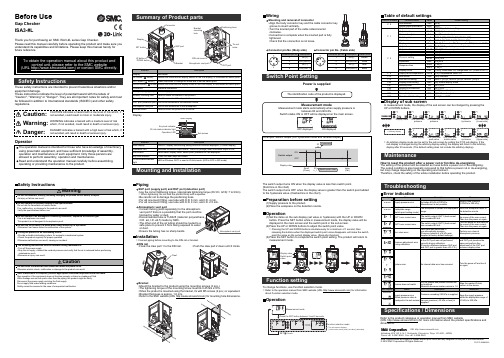
Before UseGap CheckerISA3-#LSafety InstructionsPipingSUP port (supply port) and OUT port (detection port)•Use the correct tightening torque. (Appropriate tightening torque (Rc1/8 • G1/8): 7 to 9 Nm)∗: When tightening, do not hold the product body with a spanner.•Be careful not to damage the positioning boss.•For ø6 one-touch fitting, use tube with O.D. 6 mm, and I.D. 4 mm.•For ø4 one-touch fitting, use tube with O.D. 4 mm, and I.D. 2.5 mm.Safety InstructionsMounting and InstallationThank you for purchasing an SMC ISA3-#L series Gap Checker.Please read this manual carefully before operating the product and make sure you understand its capabilities and limitations. Please keep this manual handy for future reference.These safety instructions are intended to prevent hazardous situations and/or equipment damage.These instructions indicate the level of potential hazard with the labels of"Caution", "Warning" or "Danger". They are all important notes for safety and must be followed in addition to International standards (ISO/IEC) and other safety regulations.Atmospheric vent portblocked by water or dust.O.D. ø4, I.D. ø2.5) made by SMC.or dust.•Ensure the tubing has no sharp bends.OperatorTie rod holesBracket holeBracket•Mount the bracket to the product using the mounting screws (3 pcs.).•The tightening torque of the mounting screw must be 0.45 Nm ±10%.•When the product is mounted using the bracket, fix with M5 screws (2 pcs.) or equivalent.•Bracket thickness is approx. 1.6 mm.•Refer to the SMC website (URL ) for mounting hole dimensions.Switch point valueFunction selection mode∗: The sub screen displays[ the function name ] and [ set value ] alternately.The switch output turns ON when the display value is less than switch point.(Solid line in the chart)The switch output turns OFF when the display value is greater than the switch point added to the hysteresis value. (Dashed line in the chart)To change functions, use Function selection mode.∗: Refer to the operation manual from SMC website (URL ) for information about Function selection mode.Installation∗: Connect piping before mounting to the DIN rail or bracket.DIN rail•Hook the claw part 1 to the DIN rail. •Push the claw part 2 down until it clicks.WiringMounting and removal of connector•Align the body connector key and the cable connector key groove to insert vertically.•Turn the knurled part of the cable sideconnector clockwise.•Connection is complete when the knurled part is fully tightened.Check that the connection is not loose.Switch Point SettingOperation(1)Set the items on the sub display (set value or hysteresis) with the UP or DOWN button. Press the SET button while in measurement mode, the display value will be displayed in the main screen and the switch point in the sub screen.(2)Press the UP or DOWN buttons to adjust the switch point value.∗: Pressing the UP and DOWN buttons simultaneously for a minimum of 1 second, thenreleasing the buttons when the displayed switch point value disappears, will make the switch point the same as the current display value. (Snap shot function)(3)Press the SET button to complete the switch point setting. The product will return to measurement mode.Function settingOperationDisplay of sub screenIn measurement mode, the display of the sub screen can be changed by pressing the ∗: Arbitrary displaypeak value hysteresis bottom value (Upper side)MaintenanceHow to reset the product after a power cut or forcible de-energizingThe setting of the product will be retained as it was before a power cut or de-energizing.The output condition is also basically recovered to that before a power cut or de-energizing,but may change depending on the operating environment.Therefore, check the safety of the whole installation before operating the product.Specifications / DimensionsRefer to the product catalogue or operation manual from SMC website(URL ) for more information about the product specifications and dimensions.Akihabara UDX 15F , 4-14-1, Sotokanda, Chiyoda-ku, Tokyo 101-0021, JAPAN Phone: +81 3-5207-8249 Fax: +81 3-5298-5362URL TroubleshootingConnector pin No. (Body side)Connector pin No. (Cable side)Power is suppliedPreparation before setting(1)Supply pressure to the product.(2)Place the workpiece on the detection nozzle.Note: Specifications are subject to change without prior notice and any obligation on the part of the manufacturer.© 2018 SMC Corporation All Rights Reserved Display∗: An arbitrary display mode can be set for the sub screen by setting the [F10] sub display. If the sub display is changed during the arbitrary display setting, the display will return to the arbitrary display after 30 seconds. (The default setting does not include the arbitrary display).PS ※※-OMW0010。
固德威ES系列用户手册说明书

Android marketES系列用户手册340-00006-00HYBRID INVERTER光伏储能逆变器iOS App Store 售后服务直拨热线: 400-998-1212固德威(澳洲) 19 Faireleigh Street,VIC,3046,AustraliaT: +61 3 9324 0559(售后服务)****************.cn *********************.cn固德威(中国)中国 苏州 新区科技城昆仑山路189号 T: 400-998-1212(售后服务) ****************.cn **********************.cn固德威(英国) 46 Foyle Road London N17 0NLUnited Kingdom T:44 (0)333 358 3184*******************.uk *****************.uk固德威(荷兰) Zevenwouden 194 ,3524 CX Utrecht, the Netherlands T: +31 6 1988 6498(售后服务)****************.cn *********************.cn备注:以上联系方式如有变更,恕不另行通知。
详见公司官网www .goodwe .com .cn 。
1 简介2 安全说明与警告3 设备安装4 电气连接5 EzManage 说明 (03).............................................................. 03.................................................... 04.. (05) (16) (01) (17) (18) (19) (21) (17)2.1 2.2 安全符号介绍..................................................... 01. (02)3.1 包装清单3.2 机器外观3.3 选择安装位置3.4 安装6 LED指示灯说明8 故障代码9 技术参数10 相关认证7 工作模式 (06)................................................................. 08 09............................................................................ 11................................................................. 12................................................................ 12....................... 134.1 PV 4.2 电池连接4.3 On-grid和Back-up连接4.4 EzMeter和CT 连接4.5 通讯连接4.6 Wi-Fi 连接4.7 Wi-Fi 复位和恢复出厂设置4.8 系统连接图4.9 特殊的后备连接方式连接 (16) (13)1 简介● 在使用逆变器之前,请仔细阅读本机器及说明书上的所有标签及警示标示,把说明书存放在容易找到的地方。
手机code码集
CODE: 0567045: 英国/ 爱尔兰 灰
CODE: 0558842: 独联体 灰
CODE: 0561182: 意大利 白
CODE: 0558844: 乌克兰 灰
CODE: 0558795: 希腊 灰
CODE: 0558794: 罗马尼亚 灰
CODE: 0558797: 波兰 灰
亚洲,东南亚,大洋洲 部分:
CODE:0566235 :印度
灰
CODE:0566234 :印度
白
CODE:0561931 :印度
白
CODE:0561930 :新西兰 白
CODE:0561932 :泰国 白
CODE:0567047 :老挝 灰
CODE:0561924 (0569997):香港 白
CODE:0561925 :新加坡 白
CODE:0561928 :印尼 白
CODE:0561929 :澳大利亚 白
CODE:0567052 :老挝 白
CODE:0560658 :新西兰 灰
CODE:0560656 :印尼 灰
CODE: 0569276: 保加利亚 灰
CODE: 0558783: 芬兰 灰
CODE: 0559570: 以色列 灰
CODE: 0558786: 奥地利 灰
CODE: 0558784: 丹麦 灰
CODE: 0558785: 德国 灰
CODE: 0553619: 欧元区K1 灰
灰
CODE:0566234 :印度
白
CODE:0561931 :印度
白
CODE:0561930 :新西兰 白
Case IH tractor 引擎详细信息说明书

Make Fits Application Page Engine DetailsAllis Chalmers 9435 Tractor | 9455 Tractor | 9635 Tractor | 9655TractorIH-466-O DT466 / 7.6L > PLN # 850654-888340Allis Chalmers9675 Tractor | 9695 Tractor | 9815 Tractor IH-530-A CC6.87 & T6.87 Perkins >Allis Chalmers9785 Tractor IH-530-C I530E > HEUI Thru Serial # 1194038Case-IH385 Tractor | 395 Tractor IH-155-E D155 Neuss > Late, 4.658-4.667" O-Ring Groove, 4.75MM Liner O-RingCase-IH 3220 Tractor | 380B Tractor | 484 Tractor | 485Tractor | 495 TractorIH-179-ED179 Neuss > Late, 4.658-4.667" O-RingGroove, 4.75MM Liner O-RingCase-IH 3230 Tractor | 584 Tractor | 585 Tractor | 595TractorIH-206-ED206 Neuss > Late, 4.658-4.667" O-RingGroove, 4.75MM Liner O-RingCase-IH684 Tractor | 685 Tractor IH-239-E D239 Neuss > Late, 4.658-4.667" O-Ring Groove, 4.75MM Liner O-RingCase-IH4210 Tractor | 685 Tractor | 695 Tractor IH-239-ID239 Neuss > Late, High Compression, 4.658-4.667" O-Ring Groove, 4.75MM LinerO-RingCase-IH884 Tractor | 885 Tractor | 895 Tractor IH-268-E D268 Neuss > Late, Rod Brg w/RH NotchCase-IH4240 Tractor | 995 Tractor IH-268-M DT268 Neuss > Turbo, Oil Hole In Rod Brg,38MM PinDresser3984 Excavator | 520B Wheel Loader IH-358-QDT358 Neuss > Early Turbo, Oil Hole In Rod Brg, 38MM Pin, 4.667-4.677" O-Ring Groove, 5.0MM Liner O-RingDresser 3984 Excavator | 520B Wheel Loader | 640Excavator | S8B Logging EquipmentIH-358-UDT358 Neuss > Late Turbo, Oil Hole In RodBrg, 38MM Pin, 4.658-4.667" O-RingGroove, 4.75MM Liner O-RingDresser A450E Grader IH-466-A D466 > Naturally AspiratedDresser540 Wheel Loader IH-466-EDT466/DTI466/DT466B Thru#193854/DTI466B/DT466C Thru#440035/DTI466C Thru #439617 > Crank #C1orC2Dresser540 Wheel Loader IH-466-I DT466B After #193854/DT466C #440036-532980/DTI466C #439618-532980 > Flat Tappet Cam, Crk Cast # C3Ford Light Truck IH-420-A 6.9L V-8 >Ford Light Truck IH-444-A7.3L V-8 > Naturally Aspirated, 1.110" PinFord Light Truck IH-444-B 7.3L V-8 > Turbocharged, Indirect Injection,1.308" Pin, 2 Keystone RingsFord Light Truck IH-444-D 7.3DIT / T444E / Ford Powerstroke >Turbocharged, Direct InjectionHough H100C Wheel Loader | H120C Wheel Loader IH-817-A DT817 / DT817B / DT817C / DTI817 / DTI817B / DTI817C >International201 Windrower/Swather | 2300 Tractor | 354Tractor | 434 Tractor | 500 Series Crawler/CrawlerLoader | B250 Tractor | B275 Tractor | B276Tractor | TD5 Crawler/Crawler LoaderIH-144-E BD144 / BD144A / BD144C >International Diesel Engine Reference GuideTo use this International Diesel Engine Reference, locate your model of equipment or Engine and click on the text. Clicking on the text will take you to the Catalog Page of Parts for Sale for your specific Engine. You can also use the search feature within this program. For othermanufacturer's Engine Reference, click the logo at the top.International 2424 Tractor | 2444 Tractor | 3414 Tractor | 3444Tractor | 364 Tractor | 384 Tractor | 424 Tractor |444 Tractor | 500 Crawler/Crawler Loader | 7000Forklift | 93 Combine | B414 TractorIH-154-A BD154 / BD154C / BD154T >International385 Tractor | 500C Crawler/Crawler Loader IH-155-A D155 Neuss > Early, 4.667-4.677" O-Ring Groove, 5.0MM Liner O-RingInternational340 Tractor | TD340 Crawler/Crawler Loader IH-166-A D166 > Early, 4.165" Liner Flange OD International TD340 Crawler/Crawler Loader IH-166-C D166 > Late, 3.873" Liner Flange ODInternational 2400A Tractor | 3400A Tractor | 4500 Forklift | 454Tractor | 464 Tractor | 484 Tractor | 553 TractorIH-179-AD179 Neuss > Early, 4.667-4.677" O-RingGroove, 5.0MM Liner O-RingInternational484 Tractor IH-179-E D179 Neuss > Late, 4.658-4.667" O-Ring Groove, 4.75MM Liner O-RingInternational 2500 Constructall Tractor | 2504 Tractor | 3514Series Tractor | 504 TractorIH-188-A D188 > Early, 4.165" Liner Flange ODInternational 2500 Constructall Tractor | 2504 Tractor | 3514Series Tractor | 504 TractorIH-188-E D188 > Late, 3.873" Liner Flange ODInternational100 Wheel Loader | 105 Combine | 275Windrower/Swather | 375 Windrower/Swather |584 Tractor | 624 Tractor | 654 Tractor | TD7Crawler/Crawler LoaderIH-206-AD206 Neuss > Early, 4.667-4.677" O-RingGroove, 5.0MM Liner O-RingInternational 100 Wheel Loader | 584 Tractor | TD7Crawler/Crawler LoaderIH-206-ED206 Neuss > Late, 4.658-4.667" O-RingGroove, 4.75MM Liner O-RingInternational101 Combine | 460 Tractor IH-236-A D236 > .875" PinInternational 101 Combine | 2606 Tractor | 460 Tractor | 606TractorIH-236-ED236 > 1.125" Pin, " Flg (4.165" Flg OD), 33/4" Thrust Main Brg Flg DiameterInternational2606 Tractor | 3616 Tractor | 606 Tractor IH-236-I D236 > 4.165" Liner Flange OD, 4" Thrust Main Brg Flg DiameterInternational 2606 Tractor | 315 Combine | 3616 Tractor | 606TractorIH-236-M D236 > 3.873" Liner Flange ODInternational 100E | 125 | 2500 | 2500A | 2500B | 2505B | 250A |2510B | 2514B | 2544 | 260A | 3500A | 3514 | 4000 |5000 | 544 | 5500 | 574 | 664 | 674 | 684 | 724 | 824 |TD7EIH-239-AD239 Neuss > Early, 4.667-4.677" O-RingGroove, 5.0MM Liner O-RingInternational 100E | 125C | 2500 | 2500A | 2500B | 2505B | 250A| 2510B | 2514B | 2544 | 260A | 3500A | 3514 | 4000| 5000 | 514 | 5500 | 574 | 684 | TD7E | TD8CIH-239-ED239 Neuss > Late, 4.658-4.667" O-RingGroove, 4.75MM Liner O-RingInternational 125E Crawler/Crawler Loader | TD8ECrawler/Crawler LoaderIH-239-QDT239 Neuss > Early Turbo, 38MM Pin,4.667-4.677" O-Ring Groove,5.0MM LinerO-RingInternational 125E Crawler/Crawler Loader | TD8ECrawler/Crawler LoaderIH-239-UDT239 Neuss > Late Turbo, 38MM Pin,4.658-4.667" O-Ring Groove, 4.75MM LinerO-RingInternational784 Tractor | 844 Tractor | Hydro 84 Tractor IH-246-A D246 Neuss >International ID6 Tractor | MD Tractor | MDV Tractor | ODS6Tractor | TD6 Crawler/Crawler Loader | WD6TractorIH-248-I D248 > 4.125" Parent Bore in BlockInternational400 Tractor | Super MD Tractor | Super MDVTractor | Super WD6 Tractor | T6 (61 Series)Crawler/Crawler Loader | UD264 Industrial/PowerUnit | W400 TractorIH-264-E D264 > 4.250" Parent Bore in BlockInternationalB450 Tractor | BMD Crawler/Crawler Loader |BTD100 Crawler/Crawler Loader | BTD6Crawler/Crawler Loader | BWD6 Crawler/CrawlerLoaderIH-264-I BD264 > British DieselInternational 270A Backhoe/Backhoe Loader | 510 WheelLoader | 884 Tractor | TD8C Crawler/CrawlerLoaderIH-268-AD268 Neuss > Early, Rod Brg w/LH Notch,4.667-4.677" O-Ring Groove,5.0MM LinerO-RingInternational 270A Backhoe/Backhoe Loader | 510 WheelLoader | 884 Tractor | TD8C Crawler/CrawlerLoaderIH-268-CD268 Neuss > Mid, Rod Brg w/LH Notch,4.658-4.667" O-Ring Groove, 4.75MM LinerO-RingInternational 270A Backhoe/Backhoe Loader | 4230 Tractor |510 Wheel Loader | 884 Tractor | 885 Tractor |895 Tractor | TD8C Crawler/Crawler LoaderIH-268-E D268 Neuss > Late, Rod Brg w/RH NotchInternational 450 Tractor | T6 (61 Series) Crawler/CrawlerLoader | UD281 Industrial/Power Unit | W450TractorIH-281-E D281 > 4.250" Parent Bore in BlockInternational560 Tractor | 660 Tractor IH-282-A D282 > .875" PinInternational 151 | 181 | 214 | 214A | 220 | 220A | 403 | 414 | 420| 560 | 615 | 660 | TD6 | TD9 | TD9BIH-282-ED282 / DT282 > 1.125" Pin, 3 3/4" ThrustMain Brg Flg DiameterInternational 2656 | 2706 | 403 | 414 | 416 | 420 | 422 | 560 | 615 |656 | 660 | 706 | TD6 | TD9BIH-282-ID282 / DT282 > 4.165" Liner Flange OD, 4"Thrust Main Brg Flg DiameterInternational 2656 Tractor | 2706 Tractor | 3800 Tractor | 3850Tractor | 416 Cotton Picker/Stripper | 422 CottonPicker/Stripper | 656 Tractor | 706 Tractor | TD6-62 Crawler/Crawler Loader | TD9BCrawler/Crawler LoaderIH-282-M D282 / DT282 > , 3.873" Liner Flange ODInternational403 Combine | 403 Hillside Combine | 453Hillside Combine | 503 Combine | 715 CombineIH-301-E D301 > Sleeveless EngineInternational 2706 | 2756 | 616 | 622 | 686 | 706 | 715 | 756 | 782 |86 Hydro | 9000 | 95 | S9AIH-310-AD310 Neuss > Early, 4.667-4.677" O-RingGroove, 5.0MM Liner O-RingInternational686 Tractor | 715 Combine | 782 CottonPicker/Stripper | 9000 Forklift | 95 CottonPicker/Stripper | Hydro 86 Tractor | S9A LoggingEquipmentIH-310-ED310 Neuss > Late, 4.658-4.667" O-RingGroove, 4.75MM Liner O-RingInternational 666 Tractor | 686 Tractor | Hydro 70 Tractor |Hydro 86 TractorIH-312-A D312 /InternationalID9 Tractor | OD9 Tractor | TD9 Crawler/CrawlerLoader | UD9 Industrial/Power Unit | WD9 Tractor| WDR9 TractorIH-335-ED335 > Early, 3.623" Rod Journal, 4.650"Parent Bore in Block, Piston Has .175"Deep Concave TopInternational ID9 Tractor | OD9 Tractor | TD9 Crawler/CrawlerLoader | UD9A Industrial/Power Unit | WD9Tractor | WDR9 TractorIH-335-ID335 > Late, 2.748" Rod Journal, 4.650"Parent Bore in BlockInternational 600 Tractor | 650 Tractor | Super WD9 Tractor |Super WDR9 Tractor | TD9-91 Crawler/CrawlerLoader | UD350 Industrial/Power UnitIH-350-E D350 > 4.750" Parent Bore in BlockInternational 2826 Tractor | 786 Tractor | 826 Tractor | 886TractorIH-358-AD358 Neuss > Early, 4.667-4.677" O-RingGroove, 5.0MM Liner O-RingInternational1400 Cotton Picker/Stripper | 1420 Combine |3088 Tractor | 3288 Tractor | 520B Wheel Loader |886 TractorIH-358-ED358 Neuss > Mid, 4.658-4.667" O-RingGroove, 4.75MM Liner O-RingInternational1620 Combine | 3088 Tractor | 3288 Tractor IH-358-ID358 Neuss > Late, High Compression, 4.658-4.667" O-Ring Groove, 4.75MM LinerO-RingInternational 782 High Drum Cotton Picker/Stripper | 782 LowDrum Cotton Picker/StripperIH-358-MD358 Neuss > Late, Rod Brg w/Oil Hole,4.658-4.667" O-Ring Groove, 4.75MM LinerO-RingInternational3984 Excavator | 520B Wheel Loader IH-358-QDT358 Neuss > Early Turbo, Oil Hole In Rod Brg, 38MM Pin, 4.667-4.677" O-Ring Groove, 5.0MM Liner O-RingInternational 3984 Excavator | 520B Wheel Loader | 640Excavator | S8B Logging EquipmentIH-358-UDT358 Neuss > Late Turbo, Oil Hole In RodBrg, 38MM Pin, 4.658-4.667" O-RingGroove, 4.75MM Liner O-RingInternational453 Hillside Combine | 515 Wheel Loader | 766Tractor | 886 Tractor | H60E Wheel Loader | S8ALogging EquipmentIH-360-A D360 > Naturally AspiratedInternational Mid/Heavy Truck IH-360-B DT360 / DTA360 > 1.495" Pin, Turbo, Not used in Ag, Logging, or ConstructionEquipmentInternational S10 Logging Equipment | S9B LoggingEquipmentIH-360-C DT360 > Turbo, Not used in TrucksInternational2806 Tractor | 806 Tractor IH-361-A D361 > Naturally AspiratedInternational 1206 Tractor | 21206 Tractor | E200 Scraper |TD15B Crawler/Crawler LoaderIH-361-E DT361 > TurbochargedInternational UD370 Industrial/Power Unit IH-370-A D370 > 4.750" Parent Bore in BlockInternational1026 Tractor | 1256 Tractor | 21026 Tractor |21256 Tractor | 2856 Tractor | 815 Combine | 856Tractor | TD15B Crawler/Crawler LoaderIH-407-A D407 / DT407 > 1.500" PinInternational 1456 Tractor | 21456 Tractor | 915 Combine |E200 Scraper | S11A Logging EquipmentIH-407-E DT407 > 1.625" PinInternational815 Combine | 966 Tractor IH-414-A D414 > Naturally Aspirated International1066 Tractor | 1086 Tractor | 915 Combine IH-414-E DT414 > Turbocharged International Mid/Heavy Truck IH-420-A 6.9L V-8 >International250 Crawler/Crawler Loader | 250BCrawler/Crawler Loader | 4100 Tractor | 4156Tractor | H70F Wheel Loader | TD20BCrawler/Crawler Loader | UDT429Industrial/Power UnitIH-429-E DT429 >International 100 Hydro Tractor | 1066 Tractor | 1440 Combine| 186 Hydro Tractor | 3688 Tractor | 986 TractorIH-436-A D436 > Naturally AspiratedInternational1460 Combine | 1466 Tractor | 1480 Combine |1486 Tractor | 1566 Tractor | 1586 Tractor | 3388Tractor | 4166 Tractor | 4186 Tractor | 5088Tractor | 6388 TractorIH-436-E DT436 > TurbochargedInternational Mid/Heavy Truck IH-444-A7.3L V-8 > Naturally Aspirated, 1.110" PinInternational Mid/Heavy Truck IH-444-D 7.3DIT / T444E / Ford Powerstroke >Turbocharged, Direct InjectionInternationalTD14 Crawler/Crawler Loader | TD14ACrawler/Crawler Loader | TD14A-141Crawler/Crawler Loader | TD14A-142Crawler/Crawler Loader | UD14 Industrial/PowerUnit | UD14A Industrial/Power Unit | UD461Industrial/Power UnitIH-461-A D461 >International 1640 Combine | 1822 Cotton Picker/Stripper |3488 Tractor | TD12 Crawler/Crawler LoaderIH-466-A D466 > Naturally AspiratedInternational1470 Combine | 1480 Combine | 3588 Tractor |3788 Tractor | 4366 Tractor | 4386 Tractor | 5288Tractor | 5488 Tractor | 6588 Tractor | 6788Tractor | Mid/Heavy Truck | TD15CCrawler/Crawler LoaderIH-466-EDT466/DTI466/DT466B Thru#193854/DTI466B/DT466C Thru#440035/DTI466C Thru #439617 > Crank #C1orC2International 1480 Combine | 1660 Combine | 1680 Combine |1844 Cotton Picker/Stripper | 5488 Tractor | 7288Tractor | 7488 Tractor | Mid/Heavy TruckIH-466-IDT466B After #193854/DT466C #440036-532980/DTI466C #439618-532980 > FlatTappet Cam, Crk Cast # C3International Mid/Heavy Truck IH-466-M DT466C / DTI466C #532981-850653 > RollerCamInternational Mid/Heavy Truck IH-466-O DT466 / 7.6L > PLN # 850654-888340 International Mid/Heavy Truck IH-466-Q DT466 / 7.6L > PLN After # 888340International Mid/Heavy Truck IH-466-S DT466 (175HP-210HP) / DT466 (230HP) >HEUIInternational Mid/Heavy Truck IH-466-U DT466 (230HP HT) / DT466 (250HP) > HEUI Thru Serial # 1126948International Mid/Heavy Truck IH-466-V DT466 (230HP HT) / DT466 (250HP) > HEUIInternational Mid/Heavy Truck IH-466-W DT466 > HEUI, 4.590" Bore, Late Short4.681" StrokeInternational UD16 Industrial/Power Unit IH-502-A D502 > 4.650" Parent Bore in Block International UD525 Industrial/Power Unit IH-525-A D525 > 4.750" Parent Bore in Block International Mid/Heavy Truck IH-530-A CC6.87 & T6.87 Perkins > International Mid/Heavy Truck IH-530-C I530E > HEUI Thru Serial # 1194038 International Mid/Heavy Truck IH-530-E I530E > HEUI After Serial # 1194038 International1468 Tractor | 1568 Tractor | Mid/Heavy Truck IH-550-A DV550B After Serial # 15858 / DV550C > International Mid/Heavy Truck IH-551-A9.0L >InternationalTD15-150 Crawler/Crawler Loader | TD15-151Crawler/Crawler Loader | UD554 Industrial/PowerUnitIH-554-A D554 > 4.750" Parent Bore in BlockInternational 250C Wheel Loader | 270 Scraper | E270 Scraper| H90C Wheel Loader | H90E Wheel Loader |Mid/Heavy Truck | PH65C Dump Truck | TD20CCrawler/Crawler Loader | UDT573Industrial/Power UnitIH-573-A DVT573 / DVTI573 > After Serial # 2330InternationalTD18 Crawler/Crawler Loader | TD18ACrawler/Crawler Loader | TD18A-181Crawler/Crawler Loader | TD18A-182Crawler/Crawler Loader | TD20-200Crawler/Crawler Loader | TD20-201Crawler/Crawler Loader | UD18 Industrial/PowerUnit | UD18A Industrial/Power UnitIH-691-A D691 / DT691 >International 4568 Tractor | 4586 Tractor | 4786 Tractor |Mid/Heavy Truck | TD20E Crawler/CrawlerLoaderIH-800-A DVT800 >International 295 | 295B | 330 | 340 | 4300 | 560 | D120C | E295 |H-100C | H120C | H560 | PH100 | PH100B | PH140| PH95 | TD25 | TD25B | TD25C | TD25E | TD30IH-817-ADT817 / DT817B / DT817C / DTI817 /DTI817B / DTI817C >Timberjack1270B Logging Equipment IH-466-Q DT466 / 7.6L > PLN After # 888340。
半成品编码词典
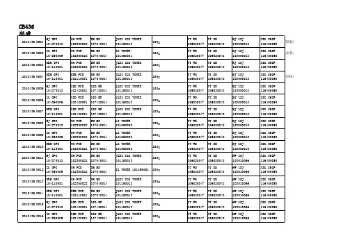
CB388半成品编码
2010388 0001 2010436 0002 2010436 0003 2010436 0004 2010436 0005 2010436 0006 2010436 0007 2010436 0008 2010436 0009 2010436 0010 2010436 0011 2010436 0012 2010436 0013 2010436 0014 2010436 0015 2010436 0016 HJ OPC 104270018 ZG OPC 104360009 OEM OPC 104110001 OEM OPC 104110001 HJ OPC 104270018 ZG OPC 104360009 OEM OPC 104110001 HJ OPC 104270018 ZG OPC 104360009 OEM OPC 104110001 HJ OPC 104270018 ZG OPC 104360009 OEM OPC 104110001 OEM OPC 104110001 HJ OPC 104270018 ZG OPC 104360009 YH PCR 102300028 YH PCR 102300028 YH PCR 102300028 OEM PCR 102110001 ZSD PCR 102420001 ZSD PCR 102420001 ZSD PCR 102420001 YH PCR 102300028 YH PCR 102300028 YH PCR 102300028 YH PCR 102300028 YH PCR 102300028 YH PCR 102300028 OEM PCR 102110001 ZSD PCR 102420001 ZSD PCR 102420001 BM MR 107040014 BM MR 107040014 BM MR 107040014 BM MR 107040014 ZSD MR 107420014 ZSD MR 107420014 ZSD MR 107420014 BM MR 107040014 BM MR 107040014 BM MR 107040014 BM MR BM MR 107040014 BM MR 107040014 BM MR 107040014 ZSD MR 107420014 ZSD MR 107420014 JADI 028 TONER 101150013 ZG TONER 101360001 JADI 028 TONER 101150013 JADI 028 TONER 101150013 JADI 028 TONER 101150013 JADI 028 TONER 101150013 JADI 028 TONER 101150013 LG TONER 101050003 LG TONER 101050003 LG TONER 101050003 JADI 028 TONER 101150013 ZG TONER 101360001 JADI 028 TONER 101150013 JADI 028 TONER 101150013 JADI 028 TONER 101150013 JADI 028 TONER 101150013 80g 80g 80g 80g 80g 80g 80g 80g 80g 80g 80g 80g 80g 80g 80g 80g YT WB 106020047 YT WB 106020047 YT WB 106020047 YT WB 106020047 YT WB 106020047 YT WB 106020047 YT WB 106020047 YT WB 106020047 YT WB 106020047 YT WB 106020047 YT WB 106020047 YT WB 106020047 YT WB 106020047 YT WB 106020047 YT WB 106020047 YT WB 106020047 YT DB 106020048 YT DB 106020048 YT DB 106020048 YT DB 106020048 YT DB 106020048 YT DB 106020048 YT DB 106020048 YT DB 106020048 YT DB 106020048 YT DB 106020048 YT DB 106020048 YT DB 106020048 YT DB 106020048 YT DB 106020048 YT DB 106020048 YT DB 106020048 MJ ZSJ 103000018 MJ ZSJ 103000018 MJ ZSJ 103000018 MJ ZSJ 103000018 MJ ZSJ 103000018 MJ ZSJ 103000018 MJ ZSJ 103000018 MJ ZSJ 103000018 MJ ZSJ 103000018 MJ ZSJ 103000018 HW ZSJ 103010066 HW ZSJ 103010066 HW ZSJ 103010066 HW ZSJ 103010066 HW ZSJ 103010066 HW ZSJ 103010066 XSG CHIP 116400050 XSG CHIP 116400050 XSG CHIP 116400050 XSG CHIP 116400050 XSG CHIP 116400050 XSG CHIP 116400050 XSG CHIP 116400050 XSG CHIP 116400050 XSG CHIP 116400050 XSG CHIP 116400050 XSG CHIP 116400050 XSG CHIP 116400050 XSG CHIP 116400050 XSG CHIP 116400050 XSG CHIP 116400050 XSG CHIP 116400050 审核: 拟制: 会签:
Multi-Port Valve User Manual

RMULTI-PORT VALVE USER MANUALFor CMP# 27505-200-000; 27507-200-000PRODUCT INFORMATIONThese multi-port valves are replacements of Pentair 261055 or 261152 Valves. The filter valve features an easy-to-use lever action handle that lets you dial up to six valve/filter functions- filter, backwash, waste, rinse, closed, and recirculate. The valve has 2in FPT and bulkhead fittings of 7-1/2” centerline distance.FILTERPUMP►SAND TOP/DE BOTTOM►THROUGH FILTER►SAND BOTTOM/DE TOP►POOL RETURNFor normal filter action and vacuuming pool through filter.BACKWASHPUMP►SAND BOTTOM/DE TOP►THROUGH FILTER►SAND TOP/DE BOTTOM►WASTE For cleaning filter by reversing flow.RINSEPUMP►SAND BOTTOM/DE TOP►THROUGH FILTER►SAND BOTTOM/DE TOP►WASTEFor start-up cleaning and resetting filter bed after backwashing.WASTE PUMP►WASTEFor vacuuming directly to waste, lowering pool level or draining pool.CLOSED NO FLOW. DO NOT USE WHEN PUMP IS IN OPERATION For shutting off all flow to filter and pool.RECIRCULATEPUMP►POOL RETURNFor circulating water without going through filter.Valve Setting Water Flow Path; Setting Function27505-200-000Replacement for Pentair 261055. It works with Pentair Triton sandfilters.27507-200-000Replacement for Pentair261152. It works with Pentair Quad, FNS plus and Nautilus plus NSP D.E. filters.*Pentair is a registered trademark of Pentair Aquatic SystemsINSTALLATION & SERVICE INSTRUCTIONS• Confirm correct valve is being used for your filter type and model.• To install valve to filter, secure bulkhead nuts on valve to fittings on filter. TIGHTEN THE NUTS BY HAND ONLY. Connect pump, return, and waste lines by following the markings of the ports.• VALVE TOP IS UNDER SPRING LOAD. To open top half and service valve, evenly and alternately loosen cover screws.• To re-assemble the top half, place diverter on a smooth and firm surface. Assemble parts on shaft byfollowing Figure A. Make sure the pointer on handle and the arrow on diverter point to same direction. Press down the cover by depressing heavy-duty spring and secure handle with dowel pin.• To re-assemble the top half to valve bottom, ensure bottom gasket and diverter sealing surface areclean and free from nicks to insure positive sealing. Tighten cover screws evenly and alternately. DO NOT OVERTIGHTEN THE SCREWS.• WINTERIZATION: To winterize, drain the pump and filter per manufacturer’s instructions. Press and turn valve handle to a position that is between any two settings.1Handle 12Dowel Pin13Plastic Washer 14Top Cover15Top Cover O-ring 16Spring Washer 17Heavy Duty Spring 18Diverter O-ring 29Diverter 1Item QTY Item Description Figure A: Top Half Assy Components0313 sbFor the full list of replacement parts of this unit, please check our catalog or our website at .CUSTOM MOLDED PRODUCTS, INC | 800-733-9060 | NEWNAN, GEORGIA 30265 | Complete Top Half Assy 27507-200-100(includes 1-9)。
SMC一触即开阀门配件说明书

Piping for the One-touch fitting•Insert the tube all the way into the fittingso that it cannot be pulled out.•Insertion with excessive force can cause damage.•Ensure there is no leakage after piping.•Use the product within the specified operating pressure and temperature range.TroubleshootingSpecifications / DimensionsRefer to the product catalogue or operation manual from SMC website(URL ) for more information about the product specifications anddimensions.Note: Specifications are subject to change without prior notice and any obligation on the part of the manufacturer.© 2011-2015 SMC Corporation All Rights ReservedAkihabara UDX 15F, 4-14-1, Sotokanda, Chiyoda-ku, Tokyo 101-0021, JAPANPhone: +81 3-5207-8249 Fax: +81 3-5298-5362URL Refer to the operation manual from SMC website (URL ) for moreinformation about troubleshooting.Function SettingPress the S buttonfor 2 secondsor longer.Press the S button once in measurement mode.[P_1] or [n_1] and [the current set value] are displayed in turn.in turnS∗: For models with switch outputs for both OUT1 and OUT2, [P_2] or [n_2] will be displayed too.Set as above.∗: If a mode other than Hysteresis Mode is selected, refer to the operation manual from SMC website(URL ) or contact SMC.∗: Note that the set value and hysteresis settings are limited by each other.<Operation>(The illustration shows PFMB7201, when not using the reversed display function.)Press the △or ▽button to change the set value.The △button is to increase and the ▽button is to decrease the set value.Press the△button continuouslyto keep increasing the set value.Press the S button to complete the setting.Return to measurement mode.S∗2: This setting is only available for models with switch outputs for both OUT1 and OUT2.∗3: This setting is only available for models with the external input.∗4: This setting is only available for models with the analogue output.Peak/Bottom value displayThe maximum (minimum) flow from when the power was supplied to this moment isdetected and updated. In peak/bottom display mode, the maximum (minimum) flow isdisplayed•For peak display, when the △button is pressed for 1 second or longer,[the maximum flow] and [Hi] are displayed in turn.To release holding the display of the maximum flow, press the △button for 1 second orlonger again to return to measurement mode.•For bottom display, when the ▽button is pressed for 1 second or longer,[the minimum flow] and [Lo] are displayed in turn.To release holding the display of the minimum flow, press the ▽button for 1 second orlonger again to return to measurement mode.If the △and ▽buttons are pressed simultaneously for 1 second or longer while the flowvalue is being held, the peak (bottom) values are reset.Reset operationThe accumulated flow value can be reset, when displaying the accumlated flow.The reset the accumulated flow, press the △and ▽buttons simultaneously for1 second or longer.The peak/bottom value can be reset, when displaying the peak value (bottom value).To reset the peak/bottom value, press the △and ▽buttons simultaneously for 1 secondor longer.Key lock functionTo use each of these functions, refer to the operation manual from SMC website(URL ) or contact SMC.MaintenanceTo change setting, refer to the operation manual from SMC website(URL ) or contact SMC.12321Safety InstructionsMounting•Never mount the product in a place where it will be used as a mechanical support.•Mount the product so that the fluid flows in the direction indicated by the arrow on the sideof the body.Safety InstructionsMounting and InstallationThese safety instructions are intended to prevent hazardous situations and/orequipment damage.These instructions indicate the level of potential hazard with the labels of"Caution", "Warning" or "Danger". They are all important notes for safety and mustbe followed in addition to International standards (ISO/IEC) and other safetyregulations.InstallationPanel mounting (Only PFMB7201)•Refer to the diagram and table below for mounting details.•Refer to the dimension from SMC website (URL )for panelthickness and panel mount cut-out dimensions.OperatorBodyPFMB7201PFMB7501/7102/7202DisplayPFMB7201PFMB7501/7102/7202Bracket mounting•Refer to the diagram and table below for mounting details.•Refer to the dimension from SMC website (URL )for bracketthickness and mounting hole dimensions.Connecting/Disconnecting•When mounting the connector, insert it straight into the socket, holding the lever andconnector body, and push the connector until the lever hooks into the housing, and locks.+ 2 1-1234Power is supplied∗: The outputs will continue to operate during setting.∗: If a button operation is not performed for 30 seconds during the setting, the display will flash.(This is to prevent the setting from remaining incomplete if, for instance, an operator were to leave during setting)∗: 3 step setting mode and Function selection mode are reflected on each other.Flow Setting (set value only) of OUT1 · OUT2Flow[L/min][H_1]Switch ONSwitch OFFSet value[P_1]Outline of settingsDIN rail mounting (Only PFMB7201)•Refer to the diagram and table below formounting details.3 step setting modeIn this mode, only the set values can be input, in just 3 steps.∗: When the reversed display is used, the function of the△and▽buttons is reversed.Piping•Never mount the product upside down.•The straight piping length shall be 8 cm or longer.Otherwise, if a straight section of piping is not installed, the accuracy varies byapproximately ±2%F.S.•Avoid sudden changes in the piping size on the IN side of the product.•Do not release the OUT side piping port of the product directly to the atmospherewithout the piping connected.If the product is used with the piping port released to atmosphere, the accuracy may vary.Piping for the metal attachment•Tighten to the specified torque. Refer to the table below for the required torque values.•Use a suitable spanner for the appropriate torque. Do not use a spanner 40 cm orlonger.•If the tightening torque is exceeded, the product can be broken.If the tightening torque is insufficient, the fitting may become loose.•Avoid any sealing tape getting inside the flow path.•Ensure there is no leakage after piping.•When mounting the fitting, a spanner should be used on the metal part (attachment) ofthe fitting only.Holding other parts of the product with a spanner may damage the product.Specifically, make sure that the spanner does not damage the connector.Direct mounting•Refer to the diagram and table below for mounting details.•Refer to the dimension from SMC website (URL )for mountinghole size.Thank you for purchasing an SMC PFMB7 series Digital Flow Switch.Please read this manual carefully before operating the product and make sure youunderstand its capabilities and limitations. Please keep this manual handy forfuture reference.Before UseDigital Flow SwitchPFMB7201/7501/7102/7202Connector pin numbers (lead wire)Press the▽button continuouslyto keep decreasing the set value.PF※※-OMP0003-AHow to reset the product after a power cut or when the power has beenunexpectedly removedThe settings of the product are retained from before the power cut orde-energizing.The output condition also recovers to that before power cut or de-energizing, butmay change depending on the operating environment. Therefore, check the safetyof the whole installation before operating the product.settingsdefault settings are shown below.When the flow exceeds the set value [P_1], the switch will be turned ON.When the flow falls below the set value by the amount of hysteresis [H_1] or more, theswitch will turn OFF.If the operation shown in the diagram below is acceptable, then keep these settings.For more detailed settings, set each function in the function selection mode.Default settingsWiringConnection•Connections should only be made with the power supply turned off.•Use a separate route for the product wiring and any power or high voltage wiring.Otherwise, malfunction may result due to noise.•Ensure that the FG terminal is connected to ground when using a commerciallyavailable switch-mode power supply. When a switch-mode power supply is connectedto the product, switching noise will be superimposed and the product specification canno longer be met. This can be prevented by inserting a noise filter, such as a line noisefilter and ferrite core, between the switch-mode power supply and the product or byusing a series power supply instead of a switch-mode power supply.Error indicationNOTEThe direct current power supply used should be UL approved as follows.Circuit (class 2) of maximum 30 Vrms (42.4 V peak) or less, with UL 1310class 2 power supply unit or UL 1585 class 2 transformer.The product is a UL approved product only if it has a mark on the body.Function selection modeIn measurement mode, press the S button for 2 seconds or longer, to display [F 0].The [F] indicates the mode for changing each Function Setting.Press the S button for 2 seconds or longer in function selection mode to return tomeasurement mode.。
- 1、下载文档前请自行甄别文档内容的完整性,平台不提供额外的编辑、内容补充、找答案等附加服务。
- 2、"仅部分预览"的文档,不可在线预览部分如存在完整性等问题,可反馈申请退款(可完整预览的文档不适用该条件!)。
- 3、如文档侵犯您的权益,请联系客服反馈,我们会尽快为您处理(人工客服工作时间:9:00-18:30)。
uip_process(u8_t flag)(1)if(flag ==UIP_UDP_SEND_CONN),若是则goto udp_send;不是则向下执行;(2)if(flag == UIP_POLL_REQUEST){if(tcpstateflags== UIP_ESTABLISHED &&!uip_outstanding(uip_connr))如果处于稳定连接状态且没有数据在缓存中等待确认则:{①uip_flags = UIP_POLL;②UIP_APPCALL();③goto appsend;}goto drop;}else if(flag == UIP_TIMER){uip_len = 0;uip_slen = 0;如果连接处于等待超时关闭状态则增加超时计数器,如果到达超时期限则关闭当前连接tcpstateflags = UIP_CLOSED;if(tcpstateflags != UIP_CLOSED) 如果连接不处于关闭状态{if(uip_outstanding(uip_connr)&&(timer-- == 0)) 已经发送的数据包还未接收到对其的ACK,超时计数器减一且超时计数器值为0 {①如果到达所设定的重发次数则:1、tcpstateflags = UIP_CLOSED;关闭当前连接2、uip_flags = UIP_TIMEDOUT;通知应用程序超时;3、UIP_APPCALL();4、设置RST+ACK终止连接标志5、goto tcp_send_nodata;②没有到达设定的重发次数则重传数据:1、重置重传计数器2、 switch(tcpstateflags)根据连接处的不同状态重发不同的数据包case UIP_SYN_RCVD:goto tcp_send_synack;重新发送先前发送的SYN+ACKcase UIP_SYN_SENT:goto tcp_send_syn;重发SYN请求连接case UIP_ESTABLISHED:uip_flags = UIP_REXMIT;UIP_APPCALL(); 调用上层应用程序,通知重新生成数据重发goto apprexmit;进入重发阶段case UIP_FIN_WAIT_1:case UIP_CLOSING:case UIP_LAST_ACK:goto tcp_send_finack;重发FIN+ACK关闭连接}else if(tcpstateflags) == UIP_ESTABLISHED) 处于稳定连接状态且上次发送的数据接收到正确的ACK,可以继续发送新数据{①uip_flags = UIP_POLL;询问应用程序是否有数据要发送②UIP_APPCALL();调用应用程序产生数据③goto appsend;发送数据}}goto drop;}if(flag == UIP_UDP_TIMER){当前连接的本地端口不为0则{①uip_len = uip_slen = 0;②uip_flags = UIP_POLL;询问应用程序是否有数据要发送③UIP_UDP_APPCALL();调用应用程序产生数据④goto udp_send;}本地端口为0,表明没有建立DUP连接,则{goto drop;}}(3)检查IP帧头中的IP版本及IP头长度是否符合要求:①不符合:goto drop;丢弃此包②符合继续向下执行(4)检查目的IP地址是否为本机地址:①不是,goto drop;丢弃此包②是,向下继续执行(5)if(BUF->proto == UIP_PROTO_TCP)IP上层协议是否为TCP协议①是,goto tcp_input;进入TCP数据处理模块②不是,继续向下执行(6)if(BUF->proto == UIP_PROTO_UDP)IP上层协议是否为UDP协议①是,goto udp_input;进入UDP数据处理模块②不是,继续向下执行(7)if(BUF->proto != UIP_PROTO_ICMP) 不是TCP不是UDP也不是ICMP协议①goto drop;本机只处理UDP、TCP、ICMP数据包,其它包都将丢弃(8)运行到此处,表明接收到的是ICMP数据包,继续向下执行;———————————————————————————————————————icmp_input:此处为ICMP数据包处理部分,比较简单不做详解。
此部分仅仅接收ECHO命令,若接收到别的命令,则将数据包丢弃。
若接收到的是ECHO 命令则返回包含ECHO_REPLY的ICMP数据包给远方主机,主要是用来响应ping命令。
———————————————————————————————————————udp_input:(1)根据要求校验UDP数据(2)在UDP连接列表中寻找接收到的数据包是否属于列表中的连接,若是则goto udp_found;如果不是则goto drop;udp_found:(1)接收到数据数设置uip_flags = UIP_NEWDA TA; 将uip_sappdata ,uip_appdata指向接收到的UDP包的数据部分。
(2)调用UIP_UDP_APPCALL();使应用程序处理接收到的数据;(3)继续向下执行udp_send:(1)如果uip_slen == 0表明没有数据要发送,则直接goto drop;(2)计算UDP数据包长度,填充UDP、IP帧头中的数据长度及相关选项;(3)根据要求计算校验和;(4)goto ip_send_nolen;发送UDP数据包;———————————————————————————————————————tcp_input:(1)检查TCP校验和,若正确向下继续,若错误则丢弃此包直接返回;(2)在TCP连接列表uip_conns中轮询,检查接收到的TCP数据包是否已经建立连接(通过逐个比较源端口、目的端口和源IP是否与链接列表中的相同)。
若找到goto found;没有找到则检查接收到的TCP数据包中是否含有SYN请求建立连接标志:若没有则goto reset;发送RST+ACK断开连接;若有则检查uip_listenports监听列表,若TCP数据包目的端口在监听列表中则goto found_listen;若不在监听列表中则向下执行,进入reset;发送RST+ACK断开连接;reset:(1)接收到的是RST断开连接包,则直接丢包,返回;(2)设置RST+ACK标志,填充适当的TCP帧头;(3)goto tcp_send_noconn;发送TCP数据包;found_listen:(1)从链接列表中找出一个空链接或剩余生存时间最短的连接;(2)将找到的链接列表根据接收到的TCP数据包进行初始化;(3)设置TCP状态为UIP_SYN_RCVD;(4)向下执行,发送ACKtcp_send_synack:(1)设置ACK标志(2)向下执行tcp_send_syn:(1)设置SYN标志(2)填充TCP选项中最大报文段长度MSS(3) goto tcp_send;found:(1)若接收到的是RST数据包,则将本连接状态置为UIP_CLOSED,uip_flags = UIP_ABORT;,调用UIP_APPCALL()通知应用程序处理连接断开请求。
然后丢弃此包,直接返回;(2)检查接收到的数据包中的数据编号是否为自己等在等待的数据编号,若不是则goto tcp_send_ack;发送自己期望的数据编号的数据,即请求重传。
若是则继续向下;(3)检查接收到的数据包中是否包含ACK,若是则:①更新发送数据序列的编号,使之可以发送后续数据;②计算RTT时间,重新设置RTT时间;③uip_flags = UIP_ACKDATA;表明接收到ACK④uip_connr->len = 0;表明等待ACK的数据长度为0,即可以发送其它数据⑤继续向下;若不是:继续向下;TCP状态机switch(tcpstateflags)case UIP_SYN_RCVD:(1)检查uip_flags==UIP_ACKDATA即是否接收到对自己发送SYN的ACK确认,若是则:①cpstateflags = UIP_ESTABLISHED;/*进入ESTABLISHED状态*/uip_flags = UIP_CONNECTED;/*连接成功*②检查数据包长度是否包含数据部分,若是则uip_flags |= UIP_NEWDATA;③调用U IP_APPCALL()处理刚建立的连接和新接收到数据;⑤goto appsend;若不是则goto drop;丢包返回;case UIP_SYN_SENT:(1)如果接收到ACK且为SYN+ACK则:①检查TCP扩展选项,如果有扩展选项从中取出MSS信息;②tcpstateflags = UIP_ESTABLISHED;进入ESTABLISHED状态③设置接收编号,uip_flags = UIP_CONNECTED | UIP_NEWDATA;调用UIP_APPCALL()处理刚建立的连接和新接收到数据;④goto appsend;(2)没有接收到ACK且为SYN+ACK则:①uip_flags = UIP_ABORT;终止连接调用UIP_APPCALL();②tcpstateflags = UIP_CLOSED;关闭TCP连接③goto reset;case UIP_ESTABLISHED:(1)接收到远方主机的FIN请求:① uip_flags |= UIP_CLOSE;关闭TCP连接②如果接收到的数据包中还包含有数据则uip_flags |= UIP_NEWDATA;③调用UIP_APPCALL()处理刚关闭的连接和新接收到数据;④发送TCP_FIN +TCP_ACK,关闭连接;(2)如果接收到的数据状态为UIP_NEWDATA | UIP_ACKDATA则:①调用UIP_APPCALL();处理接收到的包;②appsend:(1)如果(uip_flags & UIP_ABORT)终止连接则①tcpstateflags = UIP_CLOSED;关闭TCP连接;②发送RST+ACK关闭连接;(2)如果(uip_flags & UIP_CLOSE)正常关闭连接则:①tcpstateflags = UIP_FIN_WAIT_1;进入等待关闭状态②发送FIN+ACK告知对方关闭连接;(3)如果uip_slen > 0有数据要发送则设置发送数据的长度apprexmit:(1)如果(uip_slen > 0 && uip_connr->len > 0)则发送PSH_ACK数据包;(2)如果(uip_flags & UIP_NEWDATA)仅仅是发送ACK,没有数据要发送则发送对接收到数据的ACK;(3) goto drop;case UIP_LAST_ACK:(1)如果uip_flags & UIP_ACKDA TA接收到对本机发送的FIN的ACK确认则:①tcpstateflags = UIP_CLOSED;将连接置为关闭状态②uip_flags = UIP_CLOSE;调用UIP_APPCALL();通知应用程序连接已经断开;case UIP_FIN_WAIT_1:(1)此时本机已经关闭连接等待对方关闭连接,如果接收到数据并不处理,仅仅将接收到数据包数目加一;(2)如果接收到FIN请求:①如果(uip_flags & UIP_ACKDATA)接收到对本机发送FIN的确认则将连接状态置为tcpstateflags = UIP_TIME_WAIT;②否则的话则将连接状态置为tcpstateflags = UIP_CLOSING;③uip_flags = UIP_CLOSE; 调用UIP_APPCALL();通知应用程序有一方已经关闭连接④goto tcp_send_ack;(2)如果(uip_flags & UIP_ACKDATA)仅仅接收到ACK则设置连接状态标志tcpstateflags = UIP_FIN_WAIT_2; 进入等待对方关闭阶段(3) 如果(uip_len > 0)表明接收到数据包则goto tcp_send_ack;发送对接收到数据的确认ACK;(4)goto drop;case UIP_FIN_WAIT_2:(1)此时本机已经关闭连接等待对方关闭连接,如果接收到数据并不处理,仅仅将接收到数据包数目加一;(2)如果接收到对方发送的FIN请求。