NT50198_Draft_Spec_V0.05_20120907
CommScope 产品说明书

660000222 Rev C Page © 2019 CommScope.All Rights er Manual INTRODUCTION . . . . . . . . . . . . . . . . . . . . . . . . . . . . . . . . . . . . . . . . . . . . . . . . . . . . . . . . . . . . . . . . . . . . . . . . . . . . . .2Revision History . . . . . . . . . . . . . . . . . . . . . . . . . . . . . . . . . . . . . . . . . . . . . . . . . . . . . . . . . . . . . . . . . . . . . . . .2Trademark Information. . . . . . . . . . . . . . . . . . . . . . . . . . . . . . . . . . . . . . . . . . . . . . . . . . . . . . . . . . . . . . . . . . . .2Applicable Standards . . . . . . . . . . . . . . . . . . . . . . . . . . . . . . . . . . . . . . . . . . . . . . . . . . . . . . . . . . . . . . . . . . . . .2Admonishments. . . . . . . . . . . . . . . . . . . . . . . . . . . . . . . . . . . . . . . . . . . . . . . . . . . . . . . . . . . . . . . . . . . . . . . . .3General Safety Precautions . . . . . . . . . . . . . . . . . . . . . . . . . . . . . . . . . . . . . . . . . . . . . . . . . . . . . . . . . . . . . . . . .31PRODUCT DESCRIPTION. . . . . . . . . . . . . . . . . . . . . . . . . . . . . . . . . . . . . . . . . . . . . . . . . . . . . . . . . . . . . . . . . . .31.1General Description . . . . . . . . . . . . . . . . . . . . . . . . . . . . . . . . . . . . . . . . . . . . . . . . . . . . . . . . . . . . . . . .31.2Major Components . . . . . . . . . . . . . . . . . . . . . . . . . . . . . . . . . . . . . . . . . . . . . . . . . . . . . . . . . . . . . . . . .31.3Transportation and Storage . . . . . . . . . . . . . . . . . . . . . . . . . . . . . . . . . . . . . . . . . . . . . . . . . . . . . . . . . . .51.4Specifications . . . . . . . . . . . . . . . . . . . . . . . . . . . . . . . . . . . . . . . . . . . . . . . . . . . . . . . . . . . . . . . . . . . .62UNPACKING AND INSPECTION. . . . . . . . . . . . . . . . . . . . . . . . . . . . . . . . . . . . . . . . . . . . . . . . . . . . . . . . . . . . . . .63UNPACKING A PANEL WITH A PRETERMINATED CABLE. . . . . . . . . . . . . . . . . . . . . . . . . . . . . . . . . . . . . . . . . . . . . .6(continued)Content Page26379-ATECP-91-005Rev F, January 2019EHDEnhanced High Density (EHD) PanelWith Preterminated CableTECP-91-005 • Rev F • January 20194PANEL INSTALLATION. . . . . . . . . . . . . . . . . . . . . . . . . . . . . . . . . . . . . . . . . . . . . . . . . . . . . . . . . . . . . . . . . . . 134.1Overview . . . . . . . . . . . . . . . . . . . . . . . . . . . . . . . . . . . . . . . . . . . . . . . . . . . . . . . . . . . . . . . . . . . . . . 134.2Tools and Hardware Needed. . . . . . . . . . . . . . . . . . . . . . . . . . . . . . . . . . . . . . . . . . . . . . . . . . . . . . . . . 134.3Mounting an Unloaded Panel . . . . . . . . . . . . . . . . . . . . . . . . . . . . . . . . . . . . . . . . . . . . . . . . . . . . . . . . 134.4Grounding the Panel . . . . . . . . . . . . . . . . . . . . . . . . . . . . . . . . . . . . . . . . . . . . . . . . . . . . . . . . . . . . . . 165GENERAL CABLE REQUIREMENTS. . . . . . . . . . . . . . . . . . . . . . . . . . . . . . . . . . . . . . . . . . . . . . . . . . . . . . . . . . . 176OPERATION . . . . . . . . . . . . . . . . . . . . . . . . . . . . . . . . . . . . . . . . . . . . . . . . . . . . . . . . . . . . . . . . . . . . . . . . . . 186.1Sliding Out Blade to First Position. . . . . . . . . . . . . . . . . . . . . . . . . . . . . . . . . . . . . . . . . . . . . . . . . . . . . 186.2Accessing Connectors on Back of Adapter Pack . . . . . . . . . . . . . . . . . . . . . . . . . . . . . . . . . . . . . . . . . . . . 196.3Closing Blade. . . . . . . . . . . . . . . . . . . . . . . . . . . . . . . . . . . . . . . . . . . . . . . . . . . . . . . . . . . . . . . . . . . 196.4Removing Blade from Front . . . . . . . . . . . . . . . . . . . . . . . . . . . . . . . . . . . . . . . . . . . . . . . . . . . . . . . . . 206.5Removing Fiber Cover . . . . . . . . . . . . . . . . . . . . . . . . . . . . . . . . . . . . . . . . . . . . . . . . . . . . . . . . . . . . . 216.6Re-Installing Fiber Cover . . . . . . . . . . . . . . . . . . . . . . . . . . . . . . . . . . . . . . . . . . . . . . . . . . . . . . . . . . . 217TECHNICAL ASSISTANCE. . . . . . . . . . . . . . . . . . . . . . . . . . . . . . . . . . . . . . . . . . . . . . . . . . . . . . . . . . . . . . . . . 22INTRODUCTIONThis user manual describes the Enhanced High Density (EHD) Panel, Included in thisuser manual are all procedures required in installing the EHD Panel as well asoperation procedures.Revision HistoryISSUE DATE REASON FOR CHANGE19/2015Original.210/2015Added minimum cable bend radius and maximum patch cord size.33/2016Added applicable standards and panel grounding instructions.4July 2016Updated for front-access only designE October 2017Updated for product name change to SYSTIMAX.F January 2019Removed SYSTIMAX name; added transportation and storage guidelines. Trademark InformationCommScope (logo), CommScope, and Enhanced High Density Panel are trademarks. Applicable StandardsUL 60950-1, 2nd Edition, 2007-03-27 (Information Technology Equipment - Safety -Part 1: General RequirementsCSA C22.2 No. 60950-1-07, 2nd Edition, 2007-03 (Information Technology Equipment-Safety - Part 1: General Requirements)Page 2© 2019 CommScope. All Rights Reserved.TECP-91-005 • Rev F • January 2019Page 3© 2019 CommScope . All Rights Reserved.AdmonishmentsImportant safety admonishments are used throughout this manual to warn of possible hazards to persons or equipment. The admonishments — in the form of Dangers, Warnings, and Cautions — must be followed at all times.General Safety Precautions1PRODUCT DESCRIPTION 1.1General DescriptionThe Enhanced High Density (EHD) Panel is a pre-terminated fiber optic connector panel intended for use in large data centers in a direct connect or interconnect environment. The EHD Panel mounts in a 19-inch (48.26 cm) equipment rack with a 3-inch or 5-inch channel. In each 1RU of rack space, a fully loaded panel provides 144 LC terminations using duplex LC adapters.The EHD Panel is designed for ease of installation and access. It is available witheither left- or right-side cable entry. The panel features sliding blades (three per 1RU ofrack space), providing full access to adapters and connectors. Each blade can accommodate four adapter packs. The EHD Panel is available with either a black or sky white baked enamel exterior.1.2Major ComponentsFigure 1shows the main components of the EHD Panel. They are as follows:Danger is used to indicate the presence of a hazard that will cause severe personalWarning is used to indicate the presence of a hazard that can cause severeCaution is used to indicate the presence of a hazard that will or can causeWhen mounting equipment in the rack make sure mechanical loading is evenThe rack should safely support the combined weight of all equipment it supports.This equipment is to be installed only in Restricted Access Areas (dedicatedand 110-18 of the National Electrical Code, ANSI/NFPA 70.In this figure, the 2RU panel is shown. Main components are analogous forTECP-91-005 • Rev F • January 2019•Blade—holds adapter packs or cabled modules; slides out to two front access positions and is removable from front. There are three blades per RU rack space.REFERENCE)Figure 1. EHD Panel Main Components (2RU Model Shown)•Fiber Cover—holds down fibers on each blade to prevent them from being inadvertently snagged or misrouted.•Grounding Location—is where a two-hole lug and ground wire are attached to connect panel ground PEM nuts to office ground. A two-hole lug is provided withthe product; the ground wire is not.•Mounting Brackets—can be flipped around to provide either front- or rear-facing mounting on a channel rack.•Front Door—swings down to provide access to the interior of the panel. The door features a double hinged design that allows users to open the door withoutinterfering with equipment below the panel on the same rack, or also to allow thedoor to lay flat for easy access to the bottom blade.•Designation Label—provides physical space for recording fiber designations.•Duplex LC Adapter Pack—(shown for reference) mounts within the blade.Product offerings for adapter packs include LC adapter packs in singlemode APCor UPC style.Page 4© 2019 CommScope. All Rights Reserved.TECP-91-005 • Rev F • January 2019Page 5© 2019 CommScope . All Rights Reserved.1.3Transportation and StorageProducts packaged in cartons may be stacked two high in transportation and storage. Some products packaged in spools may be stacked two high in transportation and storage as shown in Figure 2. See product packaging labels for designation.Figure 2. Stacked SpoolsTECP-91-005 • Rev F • January 2019Page 6© 2019 CommScope . All Rights Reserved.1.4SpecificationsTable 1 lists specifications for the EHD Panel. Table 2 summarizes the supported adapter packs and modules for the EHD Panel.2UNPACKING AND INSPECTION1.Inspect the exterior of the shipping container(s) for evidence of rough handlingthat may have damaged the components in the container.2.Unpack each container while carefully checking the contents for damage andverify with the packing slip.3.If damage is found or parts are missing, file a claim with the commercial carrierand notify CommScope Customer Service. Save the damaged cartons for inspection by the carrier.4.Refer to Topic 7 on Page 22 if you need to contact CommScope.5.Save shipping containers for use if equipment requires shipment at a future date.3UNPACKING A PANEL WITH A PRETERMINATED CABLEThe pre-terminated panel is shipped with the panel mounted on top of a spool containing the cable. The stub end of the cable is unwound to a splice vault or other point of termination. To protect the panel and cable windings contained within the upper cylinder of the shipping unit, It is critical to leave the foam packaging material surrounding the panel in place until the unit has been transported to the final installation location. Transporting the unit without the foam packaging in place may result in damage to the panel and/or cable. To unpack and mount a fully loaded panel, use the following procedure.Table 1. EHD Panel Specifications PARAMETER SPECIFICATION REMARKSOperating conditions−14°F to +140°F (−10°C to +60C) Humidity10% to 95% RH No condensation Storage conditions−40°F to +158°F (−40°C to +70°C) Dimensions (2RU) D x W x H(with mounting brackets)19.64 in. (49.9 cm) D x 19.09 in. (48.5 cm) W x 3.5 in. (6.04 cm) H Width without mounting brack-ets: 17.27 in. (43.9 cm)Weight per 2RU 23.4 lbs. (1.06 Kg)Table 2. EHD Panel Supported Adapter Packs and ModulesDESCRIPTIONFRONT CONNECTOR TYPE FRONT PORT COUNT REAR CONNECTOR TYPE REAR PORT COUNT FIBER CONFIGURATION LC Adapter Pack LC 24LC 24NATECP-91-005 • Rev F • January 2019Page 7© 2019 CommScope . All Rights Reserved.1.Cut off the external plastic as shown in Figure 3.Figure 3. Cutting Off External Plastic2.Cut off the cardboard wrap on the cable spool as shown in.Figure 4.Figure 4. Cutting Off Cardboard Wrap on Cable SpoolUse caution when unpacking and installing the EHD Panel. Avoid twistingUse caution when removing packaging materials. Sharp utensils canTECP-91-005 • Rev F • January 20193.Remove the four carousel locking screws shown in Figure 5 to unlock thecarousel, allowing the spool to rotate freely,CABLE STUBSCREWS (4X)25873-AFigure 5. Carousel Locking Screws and Cable Stub4.Pay out the cable stub as indicated by the red arrow in Figure 5, pulling cable endto termination location.5.Remove the four wing nuts shown in Figure6.REMOVE WINGNUTS (4X)25874-AFigure 6. Removing Wing NutsPage 8© 2019 CommScope. All Rights Reserved.TECP-91-005 • Rev F • January 2019Page 9© 2019 CommScope . All Rights Reserved.6.Lift off the top cover to expose the panel packaging as shown in Figure7.Figure 7. Lifting Off Top CoverTECP-91-005 • Rev F • January 2019Page 10© 2019 CommScope . All Rights Reserved. 7.Remove the outer rim as shown in Figure 8.Figure 8. Lifting Off Outer Rim8.Remove and unpack the accessories contained in shipment carton shown on topof the packaging foam in Figure 9.Page 11© 2019 CommScope . All Rights Reserved.Figure 9. Shipment Carton Containing Accessories9.Remove and unpack the plastic wrapper containing the EHD Panel, as shown inFigure 10.Figure 10. EHD Panel in Plastic WrapperPage 12© 2019 CommScope . All Rights Reserved.10.Lift panel off of spool and carefully uncoil remaining cable. Use caution to avoidtwisting the cable. Refer to Figure 11.Figure 11. Lifting Off EHD Panel11.Follow the procedure given in Topic 4 to install the panel on the frame.12.Splice cable stub end per local practice, using blocking kit if required.Page 13© 2019 CommScope . All Rights Reserved.4PANEL INSTALLATION4.1OverviewThe EHD Panel is shipped on a spool, preterminated with 144 LC connectors per rack unit (RU). It is available in both left- and right-cable-entry versions. A blocking kit is provided for the purpose of splicing the provided cable into a splice bay such as the OMX.After mounting, the panel must be grounded. Use a #2 Phillips Screwdriver to tighten the M4 screws through the ground lug (provided) into the panel ground PEM nuts, as described in Topic 4.4 on Page 16. Ground cables are NOT provided with the panel.4.2Tools and Hardware NeededUse a #2 Phillips Screwdriver and the supplied #12-24 screws to secure the panel to the equipment rack.4.3Mounting an Unloaded PanelThe panel is to be installed in a 19-inch (482.6mm) equipment rack with a 3-inch or 5-inch channel. Use the following procedure to mount the 1RU/2RU panel.1.Obtain the following tools and equipment:•Phillips #2 screwdriver;•Mounting hardware provided.2.Determine whether the panel will be installed on front or rear and whether on a 3-inch or 5-inch channel. Install the mounting brackets provided in the locations shown in the following figures (which are representative of other RU sizes, also):•Figure 12 for 2RU mounting on a 5-inch channel; •Figure 13 for 2RU mounting on a 3-inch channel;•Figure 14 for 1RU mounting on a 5-inch channel; or •Figure 15for 1RU mounting on 3-inch channel.This equipment is to be installed only in Restricted Access Areas (dedicatedand 110-18 of the National Electrical Code, ANSI/NFPA 70.The panel is shipped with the mounting brackets already installed in the the rear position.Figure 12. 2RU Mounting Bracket Positions (Front and Rear on 5-Inch Channel)Figure 13. 2RU Mounting Bracket Positions (Front and Rear on 3-Inch Channel) Page 14© 2019 CommScope. All Rights Reserved.Figure 14. 1RU Mounting Bracket Positions (Front and Rear on 5-Inch Channel)Figure 15. 1RU Mounting Bracket Positions (Front and Rear on 3-Inch Channel)3.Hold the panel up to the assigned mounting space and align the holes in themounting brackets with the holes in the equipment rack as shown in Figure 16.Secure the panel to equipment rack using the #12-24 screws provided. Torque these screws to approximately 27 pound-inches (3.1 Newton meters).Page 15© 2019 CommScope. All Rights Reserved.Figure 16. Mounting the Panel on the Equipment Rack (2RU Model Shown)4.4Grounding the PanelA termination (for an M4 screw) is provided on the panel for a frame groundconnection. The connection must be made in accordance with local and nationalelectrical codes. Use the following procedure, referring to Figure 17.1.Locate the ground location on the panel. At the grounding location, remove theprotective tape from the panel.Page 16© 2019 CommScope. All Rights Reserved.Page 17© 2019 CommScope . All Rights Reserved.Figure 17. Grounding the Paneling AWG 14 (1.6mm) solid copper wire, secure a crimp lug to one end of theground wire (installer provided). Secure the crimp lug to panel with two M4 screws. Torque the screws to approximately 15 pound-inches (1.7 Newton meters).3.Connect the other end of the ground wire to the earth ground conductor. Ensurethis connection is made using methods and hardware that meets all applicable local and national electrical codes.5GENERAL CABLE REQUIREMENTSPre-terminated EHD Panels use RBR G657.A1 reduced-bend-radius singlemode fiber. Installers need to follow the manufacturer recommended settings when testingand splicing the RBR G657.A1 fiber to the G.652 standard singlemode fiber. Pleasealert contractors to this fact.The minimum cable bend radius is 10 inches (25.4 cm).CommScope recommends the following type patch cords for use in the EHD Panel: •2-Fiber UPC LC Singlemode Dual-Zip 1.7mm patch cord FPCT-SPLC-S-xMReliable earthing of rack-mounted equipment should be maintained. connections to the branch circuit.26275-A1RU CHASSISSECURE TO OFFICE GROUND•2-Fiber UPC LC Singlemode Dual-Zip 1.7mm RBR patch cord FPCTE-SPLC-S-xM•2-Fiber UPC LC Singlemode Dual-Zip 2mm patch cord FPC2-SPLC-S-xM•2-Fiber UPC LC Singlemode Dual-Zip LSZH 2mm patch cord FPCH2-SPLC-S-xM•2-Fiber UPC Duplex LC Singlemode Dual-Zip 1.7mm patch cord FPCT-SDLC-S-xM•2-Fiber UPC Duplex LC Singlemode Dual-Zip 1.7mm RBR patch cord FPCTE-SDLC-S-xM•2-Fiber UPC Duplex LC Singlemode Dual-Zip 2mm patch cord FPC2-SDLC-S-xM•1-Fiber UPC LC Singlemode 1.7mm patch cord FPCF-SPLC-S-xM•1-Fiber UPC LC Singlemode 2mm patch cord FPCM-SPLC-S-xMThe maximum patch cord size that can fit in the panel is 2mm simplex or duplex.6OPERATION6.1Sliding Out Blade to First PositionTo slide out a blade to the first (access) position, pull out the pull arm on the right sideof the panel until the blade contacts the first detent, as shown in Figure 18.Figure 18. Sliding Out Blade to First (Access) PositionPage 18Page 19© 2019 CommScope . All Rights Reserved.6.2Accessing Connectors on Back of Adapter PackTo access the connectors on the back of an adapter pack, use the following procedure (refer to Figure 19):1.Place index finger into the concave loop on the slide mechanism, place thumb onthe pull arm, and squeeze index finger and thumb together.2.Slide out the blade until it stops in the second position, which permits theconnectors on the back of an adapter pack to be accessed.Figure 19. Sliding Out Blades to Second Position6.3Closing BladeTo close a blade, push in the push handle on the right side of the panel until the bladeis fully within the panel.This is the opposite action to what is shown in Figure 18 on Page 18.Page 20© 2019 CommScope . All Rights Reserved.6.4Removing Blade from FrontTo remove a blade from the front of the panel (Figure 20):1.Deflect the tab outward on the right side of the panel.2.Pull on a gray fiber management finger (not the white pull handle). The graymanagement finger is highlighted in yellow in the figure.Figure 20. Removing Blade From FrontPulling too far will damage the ribbons entering the back of the blade on aFIBERTECP-91-005 • Rev F • January 20196.5Removing Fiber CoverTo remove the fiber covers, remove the blades as described in Topic 6.4 on Page 20until the center is fully exposed, then:1.Squeeze the fingers at the center of the covers per the arrows shown in Figure 21.2.Pull upward on the cover and lift it off the blade.Figure 21. Removing Fiber Covers6.6Re-Installing Fiber CoverTo reinstall the fiber cover:1.Align the fiber cover with its home location and tilt the cover at about a 45 degreeangle and position the tip of the cover within the guides indicated in Figure 22detail 1.Page 21© 2019 CommScope. All Rights Reserved.TECP-91-005 • Rev F • January 2019Page 222.Swing down the cover until it presses into and locks within the cover holderindicated in Figure 22 detail 2.Figure 22. Re-Installing Fiber Cover7TECHNICAL ASSISTANCETo find out more about CommScope® products, visit us on the web atFor technical assistance, customer service, or to report any missing/damaged parts,visit us at /SupportCenter。
IDOL Admin Software版本12.8.0发布说明说明书

Document Release Date:February2021 Software Release Date:February2021Legal noticesCopyright notice©Copyright2021 Micro Focus or one of its affiliates.The only warranties for products and services of Micro Focus and its affiliates and licensors(“Micro Focus”) are as may be set forth in the express warranty statements accompanying such products and services. Nothing herein should be construed as constituting an additional warranty.Micro Focus shall not be liable for technical or editorial errors or omissions contained herein.The information contained herein is subject to change without notice.Documentation updatesThe title page of this document contains the following identifying information:l Software Version number,which indicates the software version.l Document Release Date,which changes each time the document is updated.l Software Release Date,which indicates the release date of this version of the software.To check for updated documentation,visit https:///support-and-services/documentation/. SupportVisit the MySupport portal to access contact information and details about the products,services,and support that Micro Focus offers.This portal also provides customer self-solve capabilities.It gives you a fast and efficient way to access interactive technical support tools needed to manage your business.As a valued support customer,you can benefit by using the MySupport portal to:l Search for knowledge documents of interestl Access product documentationl View software vulnerability alertsl Enter into discussions with other software customersl Download software patchesl Manage software licenses,downloads,and support contractsl Submit and track service requestsl Contact customer supportl View information about all services that Support offersMany areas of the portal require you to sign in.If you need an account,you can create one when prompted to sign in.To learn about the different access levels the portal uses,see the Access Levels descriptions.ContentsNew in this Release4 Resolved Issues5 Documentation6New in this ReleaseNew in this ReleaseThe following new features were released in IDOL Admin version12.8.0.l All features that require unlicensed actions are now disabled in the IDOL Admin user interface.Previously the IDOL Admin behavior varied between features.l When running IDOL Admin with the IDOL Community component,IDOL Admin now uses a POST request when setting user passwords,instead of a GET request.This option improvespassword security,because the password is less likely to be logged(for example by a proxyserver).l When running IDOL Admin with the License Server,there is now a button to allow you to update the license,at Control>Console>Service Control>Update License.Resolved IssuesResolved IssuesThere were no resolved issues in IDOL Admin version12.8.0.DocumentationDocumentationThe following documentation was updated for IDOL Admin version12.8.0.l IDOL Admin User Guide。
coretool error code 501 -回复
coretool error code 501 -回复核心工具错误代码501在软件开发过程中,我们经常会遇到各种错误代码,其中核心工具错误代码501是一个常见的错误代码。
本文将详细介绍这一错误代码的意义、常见原因以及解决办法,并提供一些实例来帮助读者更好地理解和解决这一问题。
一、错误代码501的意义核心工具错误代码501通常表示服务器无法实现所请求的功能或无法识别请求。
换句话说,服务器不支持当前的请求方法或协议。
在HTTP协议中,501错误代码属于5xx服务器端错误类别,指示服务器无法完成客户端的请求。
这通常是由于服务器端配置问题或不完整的功能导致的。
因此,我们需要找出产生这个错误的原因,并采取相应的措施来解决它。
二、常见原因分析1. 服务器端配置问题:可能是由于服务器配置错误导致的。
例如,某些功能被禁用或未正确设置服务器的参数。
2. 请求方法不受支持:服务器无法处理或识别客户端发送的请求方法。
例如,使用了不被服务器支持的HTTP方法,或者使用了具有错误或丢失参数的方法。
3. HTTP版本不受支持:服务器不支持客户端所使用的HTTP版本。
通常来说,较旧的服务器版本可能不支持首选的HTTP版本。
4. 缺少必需的功能模块:服务器上缺少用于处理请求的必要功能模块,这可能是由于错误的安装或不完整的服务器配置导致的。
5. 代理服务器错误:如果请求通过代理服务器进行中转,那么代理服务器也可能发生错误,导致无法完成请求。
根据具体的错误场景,我们需要仔细分析问题的具体原因。
有时候,错误日志和服务器错误消息可能会提供有关是否有特定的配置问题或模块缺失的线索。
三、解决办法1. 检查请求方法和HTTP版本:首先,我们需要确保在请求中使用的方法和HTTP版本是服务器支持的。
如果不确定服务器支持的方法和版本,请查看服务器文档或联系服务器管理员。
2. 检查服务器配置:仔细检查服务器配置文件,确保所有必需的模块和功能被正确启用和配置。
Predefined Admin Order Comments 用户指南说明书

Predefined Admin Order CommentsUser/Installation GuideVersion 2.4.2Copyright © 2023 MageVision. All rights reserved.11.OverviewThe Predefined Admin Order Comments extension gives the ability to Magento admin users to create predefined admin order comments depending on different order statuses. Admin users do not have to create every time a new comment message, but they can easily select the comment message from a drop down while adding an order comment. It reduces the time to draft a comment message every time. Create and manage easily comment messages and assign them against order statuses.2.Key Features•Create predefined admin order comments depending on different order statuses•Select a predefined comment from the dropdown while adding an order comment•Create and manage easily comment messages and assign them against order statuses and stores•Reduce the time to draft a comment message every time3.Other Features•Developed by a Magento Certified Developer•Meets Magento standard development practices•Single License is valid for 1 live Magento installation and unlimited test Magento installations•Simple installation•100% open sourceCopyright © 2023 MageVision. All rights reserved.2patibilityMagento Community Edition 2.45.Download the Extension•Sign in to your account•Navigate to menu My Account → My Downloads•Find the extension and click to download it•Extract the downloaded ZIP file in a temporary directory6.Backup your web directory and store databaseBefore installing the extension, backup your web directory and store database. A ll our extensions are tested on clean Magento installations. We can not guarantee of compatibility with third party extensions or customized Magento installations. We recommend to install any extension you obtain from us on a testing Magento installation frst and then on a live Magento installation in case of incompatibility with third party extensions.Copyright © 2023 MageVision. All rights reserved.37.Installing the Extension using an archive and FTP•Upload the extracted folders and files of the extension to base (root) Magento directory. Do not replace the whole folders, but merge them. If you have downloaded the extension from Magento Marketplace, then create the following folder pathapp/code/MageVision/PredefinedAdminOrderComments and upload there the extracted folders and files.•Connect via SSH to your Magento server as, or switch to, the Magento file system owner and run the following commands from the (root) Magento directory:▪cd path_to_the_magento_root_directory▪php bin/magento maintenance:enable▪php bin/magento module:enable MageVision_PredefinedAdminOrderComments --clear-static-content▪php bin/magento setup:upgrade▪php bin/magento setup:di:compile▪php bin/magento setup:static-content:deploy▪php bin/magento maintenance:disable•Log out from Magento admin and log in againCopyright © 2023 MageVision. All rights reserved.48.Installing the Extension via composer (Magento Marketplace)•Connect via SSH to your Magento server as, or switch to, the Magento file system owner and run the following commands from the (root) Magento directory:▪cd path_to_the_magento_root_directory▪php bin/magento maintenance:enable▪composer require magevision/module-predefined-admin-order-comments▪php bin/magento module:enable MageVision_PredefinedAdminOrderComments –clear-static-content▪php bin/magento setup:upgrade▪php bin/magento setup:di:compile▪php bin/magento setup:static-content:deploy▪php bin/magento maintenance:disableCopyright © 2023 MageVision. All rights reserved.59.How to UseNavigate to Magento Admin under Stores → Configuration → MageVision Extensions → Predefined Admin OrderComments to enable the extension.Navigate to Magento Admin under Content → Predefined Admin Order Comments → Comments to create, view and manage the comments. By creating a comment you can define a title, the content, comment's status and assign it to a store and an order's status.After creating some comments, navigate to Magento admin Sales → Orders and select an order. Above the default comment area it will be displayed a drop down field with the titles of all predefined admin order comments you have created for the current order's status. Select one and you will see the below comment area to get populated with the comment's content.Copyright © 2023 MageVision. All rights reserved.6Screenshot:Predefined Admin Order Comments configurationStores → Configuration → MageVision Extensions → Predefined Admin Order CommentsCopyright © 2023 MageVision. All rights reserved.7Screenshot:Predefined Admin Order Comments gridContent → Predefined Admin Order Comments → CommentsCopyright © 2023 MageVision. All rights reserved.8Screenshot:Predefined Admin Order Comments newCopyright © 2023 MageVision. All rights reserved.9Screenshot:Predefined Admin Order Comments order viewCopyright © 2023 MageVision. All rights reserved.10Screenshot:Predefined Admin Order Comments order viewCopyright © 2023 MageVision. All rights reserved.11Screenshot:Predefined Admin Order Comments order viewCopyright © 2023 MageVision. All rights reserved.1210.SupportIf you need support or have any questions directly related to a MageVision extension, please contact us at**********************Best regards,The MageVision TeamCopyright © 2023 MageVision. All rights reserved.13。
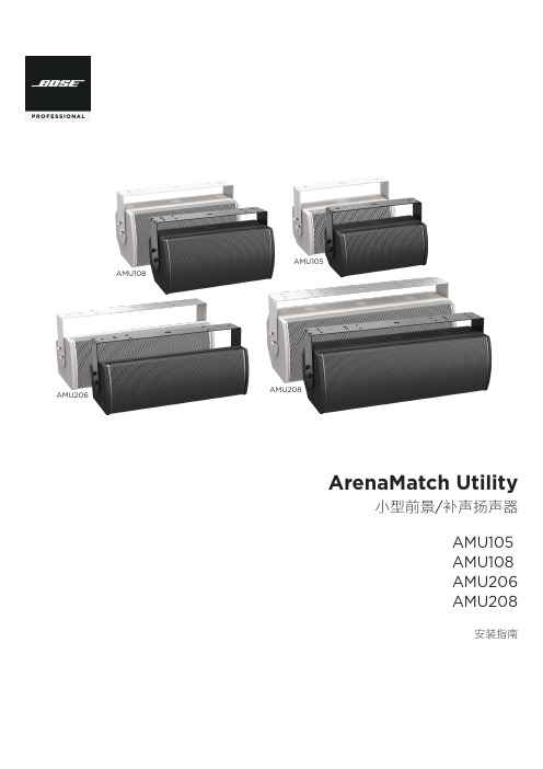
ArenaMatch Utility 小前景 补声扬声器 AMU105 AMU108 AMU206
规范信息
本产品符合所有适用的欧盟指令要求。您可以从网站 /compliance 找到完整的符合性声明。
此符号表示不得将此产品作为生活垃圾丢弃,应将其送到合适的 回收站点进行回收。正确处理和回收有助于保护自然资源、人类 健康和环境。想要获得更多关于此产品的处理和回收的信息,请 联系当地市政当局、垃圾处理服务部门或您购买此产品的商店。
中国危险物质限用表
有毒或有害物质或元素名称及成分
有毒或有害物质和元素
零件名称
铅
汞
(Pb) (Hg)
镉 ()
六价铬 (CR(VI))
多溴化 联苯 (PBB)
印刷电路板 X
O
O
O
O
金属零件
X
O
O
O
O
塑料零件
O
O
O
O
O
扬声器
X
O
O
O
O
线缆
X
O
O
O
O
此表格依据 SJ/T 11364 的要求制定。
O:表示此零件中所有均质材料所包含的此类有毒或有害物质均低于 GB/T 26572 中的限定要求。
6. 只能使用制造商指定的附件/配件。
7.
只能使用制造商指定或随本设备一起销售的推车、支架、
三角架、托架或工作台。如果使用推车,则在移动推车/设
备时应格外小心,以免因倾倒而造成伤害。
警告/小心:
包含可能导致窒息危险的小部件。不适合 3 岁以下的儿童使用。
本产品含有磁性材料。有关这是否会影响到您的植入式医疗器 械,请咨询您的医生。
包装清单................................................................................................................................................................................................... 5 可选配件................................................................................................................................................................................................... 5 检查和维护....................................................................................................................................................................................................... 6 保持防风雨性........................................................................................................................................................................................... 6 推荐使用的工具.............................................................................................................................................................................................. 6 产品尺寸........................................................................................................................................................................................................... 7 ArenaMatch Utility AMU105........................................................................................................................................................... 7 ArenaMatch Utility AMU108........................................................................................................................................................... 8 ArenaMatch Utility AMU206.......................................................................................................................................................... 9 ArenaMatch Utility AMU208........................................................................................................................................................ 10
莫萨ToughNet TN-4900系列产品介绍说明书

TN-4900SeriesEN 50155Gigabit SecurityRouterFeatures and Benefits•8Gigabit ports and up to 12PoE ports •IEC 61375ETBN functionality (ETBN models)•Dual bypass relay•Isolated power input range from 24to 110VDC •Complies with all EN 50155mandatory test items 1•-40to 70°C operating temperature range •Complies with IEC 62443-4-2:20192CertificationsIntroductionThe ToughNet TN-4900Series,designed for rolling stock Ethernet networks,is a set of high-performance M12routers with 8Gigabit ports and up to four bypass relay ports.These routers feature firewall,ETBN,and routing functionality to facilitate the deployment of applications acrossnetworks.The TN-4900Series routers use M12and other circular connectors to ensure tight,robust connections that guarantee reliability against environmental disturbances,such as vibration and shock.The TN-4900Series supports a wide power input range of 24to 110VDC and can operate in temperatures of -40to 70°C for extended periods of time.Furthermore,these routers are compliant with the mandatory requirements of EN 50155,making them suitable for a variety of industrial applications.Additional Features and Benefits•IEC 61375-2-3,61375-2-5–compliant ETBN•IEC 62443-4-2:2019–compliant cybersecurity features•Firewall to protect the network and filter untrusted network traffic •Routing functionality to divide a large network into hierarchical subnets and allow data and information to communicate across networks•NAT makes IP management easier as end devices in different carriages can use the same IP addresses•Leading EN 50155Ethernet router for rolling stock applications•Turbo Ring and RSTP/STP for network redundancy •Panel mounting installation •Line-swap fast recovery•Automatic recovery of connected device’s IP addresses•LLDP for automatic topology discovery in network management software•Configurable by web browser,Telnet/serial console,and CLI Windows utilitySpecificationsEthernet Interface10/100/1000BaseT(X)Ports (M12X-coded 8-pin female connector)TN-4908non-PoE non-ETBN Models:8TN-4908non-PoE ETBN Models:4TN-4908PoE non-ETBN Models:4TN-4916PoE non-ETBN models:410/100/1000BaseT(X)Ports (M12X-coded 8-pin female connector with bypass relay)ETBN Models:4PoE Ports (10/100BaseT(X),M12D-coded 4-pin female connector)TN-4916PoE Models:81.This product is suitable for rolling stock railway applications,as defined by the EN 50155standard.For a more detailed statement,click here:/doc/specs/EN_50155_Compliance.pdf2.Expected to be ready by the end of Q2,2023.PoE Ports(100/1000BaseT(X),M12X-coded8-pinPoE Models:4female connector)Standards IEEE802.1Q for VLAN TaggingIEEE802.1w for Rapid Spanning Tree ProtocolIEEE802.3af/at for PoE/PoE+outputIEEE802.3ab for1000BaseT(X)IEEE802.1X for authenticationIEEE802.1D-2004for Spanning Tree ProtocolIEEE802.3x for flow controlIEEE802.3u for100BaseT(X)IEEE802.1p for Class of ServiceIEEE802.3for10BaseTEthernet Software FeaturesConfiguration Options Command Line Interface(CLI)through Serial/Telnet/SSHWeb Console(HTTP/HTTPS)Windows UtilityFilter IGMP v1/v2Static Multicast802.1QManagement Back Pressure Flow ControlSNMP InformLLDPSyslogHTTPFlow controlSMTPQoS/CoS/ToSPort MirrorSNMP TrapSNMPv1/v2c/v3IPv4TelnetDHCP serverTFTPRARPAccount ManagementRedundancy Protocols RSTPStatic Port TrunkTurbo Ring v2STPRouting Redundancy VRRPSecurity Port LockSSHBroadcast storm protectionTACACS+Local Account AccessibilityHTTPS/SSLTime Management SNTPNTP Server/ClientUnicast Routing RIPV1/V2OSPFStatic RouteMulticast Routing Static RouteDoS and DDoS ProtectionTechnology NMAP-ID ScanARP-FloodSYN/FIN ScanNull ScanICMP-DeathFIN ScanSYN-FloodNEWWithout-SYN ScanXmas ScanNMAP-Xmas ScanSYN/RST ScanFirewallFilter ICMPMAC addressEthernet protocolsPortsIP addressDDoSQuick Automation Profiles TelnetHTTPRADIUSPROFINETEtherCATIPsecSSHPPTPIEC60870-104FOUNDATION FieldbusL2TPEtherNet/IPLonWorksDNPModbus TCPFTPStateful Inspection Router firewallTransparent(bridge)firewallThroughput Max.500,000packets per secondSwitch PropertiesIGMP Groups256MAC Table Size16KMax.No.of VLANs16VLAN ID Range VID1to4094LED InterfaceLED Indicators STATE,PWR1,PWR2,FAULT,10/100/1000M,PoE NATFeatures1-to-1Port forwardingN-to-1Serial InterfaceConsole Port RS-232(M12B-coded5-pin female connector) USB InterfaceM12Connector M12A-coded5-pin female(for ABC-02USB storage)Power ParametersInput Current TN-4908Non-PoE Models:0.68A@24VTN-4908PoE Models:3.6A@24VTN-4916PoE Models:5.9A@24VInput Voltage24/36/48/72/96/110VDCRedundant dual inputsNo.of power inputs:2Operating Voltage16.8to137.5VDCOverload Current Protection SupportedPower Connector M12K-coded5-pin male connectorReverse Polarity Protection SupportedTotal PoE Power Budget TN-4908PoE Models:50WTN-4916PoE Models:95WPhysical CharacteristicsHousing MetalDimensions TN-4908Non-PoE Models:160x115x70mm(6.30x4.53x2.76in)TN-4908PoE Models:160x115x100mm(6.30x4.53x3.94in)TN-4916PoE Models:206x115x100mm(8.10x4.53x3.94in)IP Rating IP40Weight TN-4908Non-PoE Models:1120g(2.47lb)TN-4908PoE Models:1640g(3.62lb)TN-4916PoE Models:1990g(4.39lb)Installation Wall mountingProtection Optional PCB conformal coatingEnvironmental LimitsOperating Temperature-40to70°C(-40to158°F)Storage Temperature(package included)-40to85°C(-40to185°F)Ambient Relative Humidity5to95%(non-condensing)Standards and CertificationsEMC EN55032,EN55035EMS IEC61000-4-3RS:80MHz to1GHz:20V/mIEC61000-4-2ESD:Contact:6kV;Air:8kVIEC61000-4-4EFT:Power:2kV;Signal:2kVIEC61000-4-5Surge:Power:2kV;Signal:2kVIEC61000-4-6CS:10VIEC61000-4-8PFMFFreefall IEC60068-2-31Radio Frequency FCCRailway EN50121-4EN50155IEC60571Railway Fire Protection EN45545-2Safety IEC62368,UL62368Shock IEC60068-2-27,IEC61373,EN50155Vibration IEC60068-2-64,IEC61373,EN50155DeclarationGreen Product RoHS,CRoHS,WEEEMTBFTime TN-4908Non-PoE Models:795,840hrsTN-4908Non-PoE ETBN Models:648,903hrsTN-4908PoE Models:644,898hrsTN-4908PoE ETBN Models:545,021hrsTN-4916PoE Models:550,148hrsTN-4916PoE ETBN Models:472,578hrsStandards Telcordia SR332WarrantyWarranty Period5yearsDetails See /warrantyPackage ContentsDevice1x TN-4900Series routerInstallation Kit2x cap,male,metal,for M12port(Console and USB storage ports,fixed on switch)4/8x cap,male,metal,for M12port(Ethernet ports,fixed on switch)1x wall-mounting kitDocumentation1x quick installation guide1x warranty cardDimensionsTN-4908Non-PoE ModelsTN-4908PoE ModelsTN-4916PoE ModelsOrdering InformationTN-4908-8GTX-WV-T✓––8–––TN-4908-8GTX-WV-CT-✓––8––✓TTN-4908-ETBN-4GTX-–✓–44––4GTXBP-WV-TTN-4908-ETBN-4GTX-–✓–44–✓4GTXBP-WV-CT-TTN-4908-ETBN-F-4GTX-✓✓–44––4GTXBP-WV-TTN-4908-ETBN-F-4GTX-✓✓–44–✓4GTXBP-WV-CT-TTN-4908-4GPoE-4GTX-✓––4–4–WV-TTN-4908-4GPoE-4GTX-✓––4–4✓WV-CT-TTN-4908-ETBN-4GPoE-–✓––44–4GTXBP-WV-TTN-4908-ETBN-4GPoE-–✓––44✓4GTXBP-WV-CT-TTN-4908-ETBN-F-✓✓––44–4GPoE-4GTXBP-WV-TTN-4908-ETBN-F-✓✓––44✓4GPoE-4GTXBP-WV-CT-TTN-4916-8PoE-4GPoE-––84–4–4GTX-WV-TTN-4916-8PoE-4GPoE-––84–4✓4GTX-WV-CT-TTN-4916-ETBN-8PoE-–✓8–44–4GPoE-4GTXBP-WV-TTN-4916-ETBN-8PoE-–✓8–44✓4GPoE-4GTXBP-WV-CT-TTN-4916-ETBN-F-8PoE-✓✓8–44–4GPoE-4GTXBP-WV-TTN-4916-ETBN-F-8PoE-✓✓8–44✓4GPoE-4GTXBP-WV-CT-TAccessories(sold separately)M12Connector CapsA-CAP-M12M-M Metal cap for M12male connectorA-CAP-M12F-M-PP Metal cap for M12female push-pull connectorConnectorsM12X-8PMM-IP67-HTG X-coded screw-in Gigabit Ethernet connector,8-pin male M12connector,IP67CablesCBL-M12XMM8P-Y-300-IP67M12-to-M12Cat-5UTP Ethernet cable,8-pin male X-coded crimp type M12connector,IP67,3mCBL-M12XMM8PRJ45-Y-200-IP67M12-to-RJ45Cat-5UTP Ethernet cable,8-pin male X-coded crimp type M12connector,IP67,2m CBL-M12XMM8P-Y-100-IP67M12-to-M12Cat-5UTP Ethernet cable,8-pin male X-coded crimp type M12connector,IP67,1mCBL-M12BMM5PF9-BK-150-IP68B-coded male M12-to-5-pin DB9console cable,IP68-rated,1.5mCBL-M12KFF5POPEN-O-150-IP67K-coded female M12-to-5-pin open wire M12power cable,IP67-rated,1.5mStorage KitsABC-02-P-USB-M12-CT-T USB-based configuration backup and restoration tool with M12connector for Moxa’s ToughNet seriesof managed Ethernet switches and wireless APs/bridges/clients,-40to75°C operating temperature,conformal coating©Moxa Inc.All rights reserved.Updated Feb07,2023.This document and any portion thereof may not be reproduced or used in any manner whatsoever without the express written permission of Moxa Inc.Product specifications subject to change without notice.Visit our website for the most up-to-date product information.。
九нов基特28,92,94,96 users 说明书

CAUTION! Caution indicates a potentially hazardous situation which, if not avoided, may result in minor or moderate injury.
Door swing clearance (top view)
EKB 9271
EKB 9471
EKB 9671
Internal door panel A = 273 mm B = 12.5 mm C = 658 mm
External door panel A = 279 mm B = 12.5 mm C = 670 mm
IMPORTANT This indicates information that is especially relevant to a problem-free installation and operation.
20
Note to the installer
It is very important to follow the instructions in the manual to ensure proper installation and operation of the appliance.
Do not use stand-alone inverters (conversion of direct current to alternating current/threephase current) or energy-saving plugs. Risk of damage to the electronic control system!
H5网络PTZ全景摄像头固件版本说明书

H5 Network PTZ Dome Camera Firmware Version: V5.5.40 Release Note(2020-06-16)1.Firmware Version Information1.1Firmware Basic InformationPTZ Camera:IPD_H5_EN_XXX_5.5.40_200518.zipIPDHG_H5_L1_EN_XXX_5.5.40_200518.zipSmart-Linkage PTZ Camera:IPDZLF_H5_EN_XXX_5.5.40_200520.zip2.Related Resource Versions2.1Built-in Resource Versions(1)SDK version: HCNetSDKV6.1.4.20_build20200320(2)iVMS 4200 client: V3.2.2.5Build20200418(3)Hybrid Target Algorithm lib(HMS): V4.3.0build200226(4)Face Capture Algorithm lib: V4.3.1build190123(5)Plugin: V4.0.1.0 build 2005122.2Protocol Versions(1)Onvif version: V17.12 test tool: 1806SR1(2)ISAPI version: 2.4(3)Ehome version: V2.0(2.1-3.0)\V4.0(4)CGI version: V2.0(5)Hik-Connect version: V1.72.3Third-party Platform Software Versions(1)Milestone s oftware version (Milestone Corporate 2019 R3), Milestone driver version (Device Pack 10.6)(2)Exacqvision s oftware: 20.03.9.0(3)Avigilon Control Center: v7.2.2.0(4)Digifort Enterprise: 72102.4Tested NVR3.Version Main Updates(Compared with V5.5.24)3.1New Features●New models are released.iDS-2SK8144IXS-D/J(40X/2812)(Overseas STD)(T2)●New functions:【1】Object capture function:The device supports the object capture, and can compare the face pictures in the face library. If the comparison is successful, the target is tracked.【2】Advanced configuration of object capturea.S upport object tracking and debugging mode. After opening, the preview screen will display trace debugging information, which is used for PK debuggingb.Support the function of object tracking and capturing. The device will capture the tracking target when setting up the control tracking. If the object t reach the capture threshold, upload the tracking captured object c.M agnification control mode: support zoom based on target frame and tracking TZ relationship during control and trackingd.Tracking failure dwell time: after tracking failure, the device will stay for a period of time before returning to the initial detection location e.Long distance transmission interval of Tracking Alarm: the frequency of uploading GPS information when the device is trackingf.Tracking duration: the maximum time for the device to track the target, 0-300s configurable.【4】Security requirementsa.Support session number, session lock, session timeout settingsb.Web components supports SSH and Bonjour configurationc.Reset password import and export key mode add error locking functiond.Reset password import and export key mode add error locking functione.SSH supports sha256 digest algorithmf.Encrypted transmission required to reset password verification codeg.No country field certificate removal restrictions.【5】General functionsa.Overseas equipment supports video expiration functionb.New certificate management functionc.New SRTP Previewd.New IP address filtering supports address segment filtering.【6】Smart-Linkage PTZ Camera requirementsa.Support gyroscope anti damage alarm functionb.Support network break exception function detection and SNMP trapfunction descriptionc.Add 1.5x gear for low illumination electronic shutterd.Support mosaic functione.Support turret camera-PTZ linkage tracking, take over tracking functionf.Support turret camera-PTZ linkage tracking and capturing functiong.Camera will add panoramic superposition tracking target frame whentracking targetsh.Sound-light-warning supports user-defined upload voice, and supports thefunction of alarm input linkage Sound-light-warning alarm.3.2Optimize●GPS function upgrade:a.Support GPS calibration validationb.GPS data will be deleted when default device, rather than restore device●Object capture and multi-target capture function upgradea.Support beautify face and plate enhancement functionb.In video structuralization, multi-target capture supports target trajectory overlayin background image and preview image●Support size filter for smart event●People arming tracking zoom rate optimization: Support gyroscope calibrationto fix the issue that device hanging out of alignment in gyroscope device.●In smart mode, multi-channel device support smart post retrieval for eachchannel●Update HMS4.3, resolve that capture dog by mistake and plate recognition withlarge pixels●Image configuration:a.Optimize Gain function: In manual exposure mode, remove Limit Gainb.When call preset, scene parameter in front-end will change at the same timec.Brightness control refinementd.Day/Night mode switch sensitivity refinement, support 7 level●Alarm protocol upgrade, support multi-time zone scheme to resolve issuecaused by different time zone●Video & Audio:a.Remove 44.1 KHZ in audio coded sampling rateb.Import CVBR encode●Network:a.Support multicast configuration interfaceb.Support LAN domain name configuration functionc.802.1X supports EAP-TLS, EAP-LEAP protocold.ISUP 5.0 cloud storage photo server configuratione.OSD word size configuration●Support storage encryption●Smart wiper supports only 1 time by default3.3Delete●Delete face arming functionCustomer Impact and Recommended ActionThis update refers to function/compatibility improvement and will take effectautomatically after the Date of Change. We are very sorry for any inconvenience ofuse-habit changes caused by this action.For any questions and request for this firmware, please contact our local technicalsupport team.Remarks:●Hikvision reserves the right to change, alter or withdraw the above notification without priornotice.●Product design and specifications are subject to change without prior notice.●The Hikvision firmware may contain errors known as errata which may cause the product todeviate from published specifications. Current characterized errata are available on request.●Hikvision is not liable for any typing or printing errors.Hikvision Digital Technology CO., Ltd.No. 555 Qianmo Road, Binjiang District, Hangzhou 310051, ChinaTel: +86-571-8807-5998FAX: +86-571-8993-5635Email:*****************************。
- 1、下载文档前请自行甄别文档内容的完整性,平台不提供额外的编辑、内容补充、找答案等附加服务。
- 2、"仅部分预览"的文档,不可在线预览部分如存在完整性等问题,可反馈申请退款(可完整预览的文档不适用该条件!)。
- 3、如文档侵犯您的权益,请联系客服反馈,我们会尽快为您处理(人工客服工作时间:9:00-18:30)。
N T50198TFT-LCD 3-Channel Charge Pump Power ICD r a f t S p e c.V e r s i o n0.052012/08/222012/08/22 1 Version 0.05 With respect to the information represented in this document, NOVATEK makes no warranty, expressed or implied, including the warranties of merchantability, fitness for a particular purpose, and non-infringement, nor assumes any legal liability or responsibility for the accuracy, completeness or usefulness of any such information.2012/08/22 2 Version 0.05With respect to the information represented in this document, NOVATEK makes no warranty, expressed or implied, including the warranties of merchantability, fitness for a particular purpose, and non-infringement, nor assumes any legal liability or responsibility for the accuracy, completeness or usefulness of any such information.I n d e xI n d e x .............................................................................................................................................................................2 Reversion History .........................................................................................................................................................4 1. General Description..................................................................................................................................................5 2. Features....................................................................................................................................................................5 3. Block Diagram and Operating Circuit.. (6)3.1:12 pins block diagram....................................................................................................................................................................................................6 3.2:16 pins block diagram case1..........................................................................................................................................................................................7 3.3:16 pins block diagram case2 (8)4. Pin Description and package (9)4.1 TDFN-12 pin....................................................................................................................................................................................................................9 4.2 TDFN-12 package............................................................................................................................................................................................................9 4.3 TDFN-16 pin..................................................................................................................................................................................................................10 4.4 TDFN-16 package..........................................................................................................................................................................................................10 4.5 QFN-16 pin.....................................................................................................................................................................................................................11 4.6 QFN-16 pins package.. (11)5. External Component List (12)5.1 12 pins component list....................................................................................................................................................................................................12 5.2 16 pins component list. (12)6. Application information (13)6.1:Power on / off sequence :...........................................................................................................................................................................................14 Case 1: EN_VCL = 1 and EN_VCL_FR = 0 (CP option):............................................................................................................................................14 Case 2: EN_VCL = 1 and EN_VCL_FR = 1 (CP option):............................................................................................................................................14 Case 3: EN_VCL = 0 and EN_VCL_FR = 0 (CP option):............................................................................................................................................15 Case 4: EN_VCL = 0 and EN_VCL_FR = 1 (CP option):............................................................................................................................................15 A VDD pre-charge to GND: control by EN_DIS2GND (CP option).............................................................................................................................16 6.2:Positive Charge Pump Controller :.............................................................................................................................................................................17 6.3:Negative Charge Pump Controller :...........................................................................................................................................................................17 6.4:Application Note :......................................................................................................................................................................................................17 6.5:Typical characteristic:..................................................................................................................................................................................................18 6.5.1 Output voltage V .S. Output current with VCL (Vin = 3V , room temperature )...................................................................................................18 6.5.2 Efficiency V .S. output current with VCL(Vin = 3V , room temperature )............................................................................................................19 6.5.3 Output voltage V .S. Output current of without VCL (Vin = 3V , room temperature )..........................................................................................20 6.5.4 Efficiency V .S. output current of without VCL (Vin = 3V , room temperature )..................................................................................................21 6.6:Two ways to enhance output current capability:..........................................................................................................................................................22 6.6.1: Dickson doubler circuit:......................................................................................................................................................................................22 6.6.2: External component table of Dickson doubler circuit:........................................................................................................................................22 6.6.3: Power On / off sequence with external Dickson mode:.......................................................................................................................................23 6.6.4: Paralleling two device circuit:.............................................................................................................................................................................24 6.6.5: External component of Paralleling two device circuit:. (26)2012/08/22 3 Version 0.05With respect to the information represented in this document, NOVATEK makes no warranty, expressed or implied, including the warranties of merchantability, fitness for a particular purpose, and non-infringement, nor assumes any legal liability or responsibility for the accuracy, completeness or usefulness of any such information.7. Package Information : (27)7.1 TDFN-12 pins package...................................................................................................................................................................................................27 7.2 TDFN-16 pins package...................................................................................................................................................................................................28 7.3 QFN-16 pins package.. (30)8. Absolute Maximum Ratings :................................................................................................................................31 9. Thermal Information :............................................................................................................................................31 10. Electrical Specifications : (32)2012/08/22 4 Version 0.05With respect to the information represented in this document, NOVATEK makes no warranty, expressed or implied, including the warranties of merchantability, fitness for a particular purpose, and non-infringement, nor assumes any legal liability or responsibility for the accuracy, completeness or usefulness of any such information.Reversion History2012/08/22 5 Version 0.05With respect to the information represented in this document, NOVATEK makes no warranty, expressed or implied, including the warranties of merchantability, fitness for a particular purpose, and non-infringement, nor assumes any legal liability or responsibility for the accuracy, completeness or usefulness of any such information.1. General DescriptionThe NT50198 is a high-performance step-up charge pump and inverter to generate two output voltages; it is including pumping controllers for positive and negative output voltage. The following content contains the detailed description and the information of component selection.The positive charge-pump controller provides adjustable regulated output AVDD and fixed -1 ratio of AVEE to supply the TFT.The pumping clock can be generated by internal circuit, to reduce the control signal from driver IC. Or the charge and pump state can be synchronized with LCD display TE signal (PSYNC), it can reduce the interference to display quality when states change.The device requires only five (12 pins) or seven (16 pins) small and low-cost ceramic capacitors.NT50198 is available in TDFN-12 / TDFN-16 / QFN-16 pins package for smart phone LCD panel’s driver IC.Note: According to the FPC layout experience, the components on the FPC may have chance to fall off when wind the FPC. So we strongly suggest to add the Stiffener under the FPC backside area of NT50198.2. FeaturesCharge pump x2 mode for positive AVDD and x-1 mode for negative AVEE .2.5V to 4.8V input supply voltage range AVDD output range :5.8V to 6.0V. AVEE output range :-5.8V to -6.0V. VCL output range :-2.5V to -3.2V.Charge pump clock synchronized with PSYNC for benefit of low noise. Positive and Negative regulated charge Pump with Diode free. External Capacitor 5C or 7C only.QFN-16 (3.0mm * 3.0mm * 0.8 mm) package is available. TDFN-12 (1.5mm * 2.4mm * 0.5 mm) package is available. TDFN-16 (1.5mm * 3.2mm * 0.5 mm) package is available. Control signals voltage 1.65V to 4.8V.2012/08/22 6 Version 0.05With respect to the information represented in this document, NOVATEK makes no warranty, expressed or implied, including the warranties of merchantability, fitness for a particular purpose, and non-infringement, nor assumes any legal liability or responsibility for the accuracy, completeness or usefulness of any such information.3. Block Diagram and Operating Circuit3.1:12 pins block diagram2012/08/22 7 Version 0.05With respect to the information represented in this document, NOVATEK makes no warranty, expressed or implied, including the warranties of merchantability, fitness for a particular purpose, and non-infringement, nor assumes any legal liability or responsibilityfor the accuracy, completeness or usefulness of any such information.2012/08/22 8 Version 0.05With respect to the information represented in this document, NOVATEK makes no warranty, expressed or implied, including the warranties of merchantability, fitness for a particular purpose, and non-infringement, nor assumes any legal liability or responsibility for the accuracy, completeness or usefulness of any such information.2012/08/22 9 Version 0.05With respect to the information represented in this document, NOVATEK makes no warranty, expressed or implied, including the warranties of merchantability, fitness for a particular purpose, and non-infringement, nor assumes any legal liability or responsibility for the accuracy, completeness or usefulness of any such information.4. Pin Description and package2012/08/22 10 Version 0.05With respect to the information represented in this document, NOVATEK makes no warranty, expressed or implied, including the warranties of merchantability, fitness for a particular purpose, and non-infringement, nor assumes any legal liability or responsibility for the accuracy, completeness or usefulness of any such information.4.4 TDFN-16 packageFigure5:TDFN-16 pins assignment2012/08/22 11 Version 0.05With respect to the information represented in this document, NOVATEK makes no warranty, expressed or implied, including the warranties of merchantability, fitness for a particular purpose, and non-infringement, nor assumes any legal liability or responsibility for the accuracy, completeness or usefulness of any such information.4.6 QFN-16 pins packageFigure7:QFN-16 pins assignment2012/08/22 12 Version 0.05With respect to the information represented in this document, NOVATEK makes no warranty, expressed or implied, including the warranties of merchantability, fitness for a particular purpose, and non-infringement, nor assumes any legal liability or responsibility for the accuracy, completeness or usefulness of any such information.5. External Component List5.1 12 pins component list2012/08/22 13 Version 0.05With respect to the information represented in this document, NOVATEK makes no warranty, expressed or implied, including the warranties of merchantability, fitness for a particular purpose, and non-infringement, nor assumes any legal liability or responsibility for the accuracy, completeness or usefulness of any such information.6. Application informationThe NT50198 can provide a suitable and stable voltage level to TFT LCD driver IC, and NT50198 can refer to PSYNC signal to switch from charge state to pump state and vice versa. This function can avoid state changing noise to interfere display quality. If the driver IC or baseband can not provide PSYNC, please connect PSYNC signal to GND pin for free-running mode (Internal frequency =125 KHz). The difference between free-running mode and sync mode is that the display quality may be worse in free-running mode. It needs larger stable capacitor to reduce the ripple noise. In sync mode, due to the noise is generated at display porch area; it will not be observed on the panels.About the power on/off sequence, please refer to the next chapter in details.2012/08/22 14 Version 0.05With respect to the information represented in this document, NOVATEK makes no warranty, expressed or implied, including the warranties of merchantability, fitness for a particular purpose, and non-infringement, nor assumes any legal liability or responsibility for the accuracy, completeness or usefulness of any such information.6.1:Power on / off sequence :Case 1: EN_VCL = 1 and EN_VCL_FR = 0 (CP option):(1)EN_VCL_FR=0EN_VCL=1SLP_OUT cmd to driver2012/08/22 15 Version 0.05With respect to the information represented in this document, NOVATEK makes no warranty, expressed or implied, including the warranties of merchantability, fitness for a particular purpose, and non-infringement, nor assumes any legal liability or responsibility for the accuracy, completeness or usefulness of any such information.Case 3: EN_VCL = 0 and EN_VCL_FR = 0 (CP option):(3)EN_VCL_FR=0EN_VCL=0SLP_OUT cmd to driver2012/08/22 16 Version 0.05With respect to the information represented in this document, NOVATEK makes no warranty, expressed or implied, including the warranties of merchantability, fitness for a particular purpose, and non-infringement, nor assumes any legal liability or responsibility for the accuracy, completeness or usefulness of any such information.AVDD pre-charge to GND: control by EN_DIS2GND (CP option)2012/08/22 17 Version 0.05With respect to the information represented in this document, NOVATEK makes no warranty, expressed or implied, including the warranties of merchantability, fitness for a particular purpose, and non-infringement, nor assumes any legal liability or responsibility for the accuracy, completeness or usefulness of any such information.6.2:Positive Charge Pump Controller :The NT50198 can provide a trimming-able pump ratio for AVDD. The ratio is adjusted 1.5x or 2.0x or 3.0x by CP option of VCI input voltage.6.3:Negative Charge Pump Controller :The NT50198 can provide a fixed pump ratio to generate AVEE. The ratio is fixed at -1.0x of AVDD.6.4:Application Note :The NT50198 has three control signals :EN_PWR / PSYNC / EN_VCL.1. EN_PWR is used for enable AVDD and AVEE charge pump circuit. When EN_PWR keeps low, it will disableoutput voltage.Note: Please do not connect EN_PWR to VCI. Host should enable EN_PWR pin while VCI power is ready2. PSYNC is used for sync mode with VCL. If EN_VCL = 1 and EN_VCL_FR = 1 (optional pin), VCL enter freepumping mode for internal clock. It will start with EN_PWR pin. If EN_VCL = 1 and EN_PWR_VCL_FR = 0, VCL enter sync mode with PSYNC. In the beginning, VCL will not enable with EN_PWR pin. When PSYNC pin starts to toggle, VCL will pump and follow the frequency of PSYNC. When PSYNC stops toggling, VCL will wait two or more clock and discharge to ground.3. EN_VCL is used for enable VCL charge pump circuit. When EN_VCL keeps low, it will disable output voltage ofVCL. EN_VCL can be connected to VCI for power-on start. (This function is available for 16 pins package only)Protection function :Over voltage protection (clamp function) is included in NT50198.2012/08/22 18 Version 0.05With respect to the information represented in this document, NOVATEK makes no warranty, expressed or implied, including the warranties of merchantability, fitness for a particular purpose, and non-infringement, nor assumes any legal liability or responsibility for the accuracy, completeness or usefulness of any such information.6.5:Typical characteristic:6.5.1 Output voltage V.S. Output current with VCL (Vin = 3V , room temperature )Note : It means when AVDD and AVEE output 20 mA at the same time ,AVDD will drop to 5.435V and AVEE will drop to -5.03V .2012/08/22 19 Version 0.05 With respect to the information represented in this document, NOVATEK makes no warranty, expressed or implied, including the warranties of merchantability, fitness for aparticular purpose, and non-infringement, nor assumes any legal liability or responsibility for the accuracy, completeness or usefulness of any such information.2012/08/22 20 Version 0.05With respect to the information represented in this document, NOVATEK makes no warranty, expressed or implied, including the warranties of merchantability, fitness for a particular purpose, and non-infringement, nor assumes any legal liability or responsibility for the accuracy, completeness or usefulness of any such information.6.5.3 Output voltage V.S. Output current of without VCL (Vin = 3V , room temperature )Note : if the capacitor of VCL(C31) does not assembly , it will degrade the AVDD output voltage level and pump efficiency . the NT50198 behavior without VCL is showed as below , the same as TDFN12 .2012/08/22 21 Version 0.05With respect to the information represented in this document, NOVATEK makes no warranty, expressed or implied, including the warranties of merchantability, fitness for a particular purpose, and non-infringement, nor assumes any legal liability or responsibility for the accuracy, completeness or usefulness of any such information.6.5.4 Efficiency V.S. output current of without VCL (Vin = 3V , room temperature )2012/08/22 22 Version 0.05With respect to the information represented in this document, NOVATEK makes no warranty, expressed or implied, including the warranties of merchantability, fitness for aparticular purpose, and non-infringement, nor assumes any legal liability or responsibility for the accuracy, completeness or usefulness of any such information.6.6:Two ways to enhance output current capability:6.6.1: Dickson doubler circuit:With heavy loading of AVDD and AVEE, NT50198 provide another option circuit to enhance AVEE circuit ability. Using VCL voltage doubler to generate 2*VCL, and connect with AVEE output pin.It needs to add 2 extra diodes, 1 capacitor and change AVEE capacitor from 2.2uF to 4.7uF and needs to be controlled by C31P signal. (Only available for 16 pin package IC)6.6.2: External component table of Dickson doubler circuit:2012/08/2223Version 0.05With respect to the information represented in this document, NOVATEK makes no warranty, expressed or implied, including the warranties of merchantability, fitness for a particular purpose, and non-infringement, nor assumes any legal liability or responsibility for the accuracy, completeness or usefulness of any such information.6.6.3: Power On / off sequence with external Dickson mode:Note : please notice the power on sequence of VCL , it must enable after AVEE , please contact with us for correct NT50198 part number .2012/08/22 24 Version 0.05With respect to the information represented in this document, NOVATEK makes no warranty, expressed or implied, including the warranties of merchantability, fitness for a particular purpose, and non-infringement, nor assumes any legal liability or responsibility for the accuracy, completeness or usefulness of any such information.6.6.4: Paralleling two device circuit:An increase in converter output current capability with a reduction in output resistance can be obtained by paralleling two devices. The output current capability is approximately equal to double for AVDD and AVEE. A single shared output capacitor is sufficient for proper operation but each device does require its own pump capacitor. Note that the output ripple frequency will be complex since the oscillators are not synchronized.<TDFN 12pin application circuit><TDFN 16pin application circuit><QFN 16pin application circuit>2012/08/22 25 Version 0.05 With respect to the information represented in this document, NOVATEK makes no warranty, expressed or implied, including the warranties of merchantability, fitness for a particular purpose, and non-infringement, nor assumes any legal liability or responsibility for the accuracy, completeness or usefulness of any such information.2012/08/22 26 Version 0.05With respect to the information represented in this document, NOVATEK makes no warranty, expressed or implied, including the warranties of merchantability, fitness for a particular purpose, and non-infringement, nor assumes any legal liability or responsibility for the accuracy, completeness or usefulness of any such information.6.6.5: External component of Paralleling two device circuit:<16pin external component table>2012/08/22 27 Version 0.05Withrespect to the information represented in this document, NOVATEKmakes no warranty,expressedor implied, including the warranties of merchantability, fitness for a particular purpose, and non-infringement, nor assumes any legal liability or responsibility for the accuracy, completeness or usefulness of any such information.7. Package Information :7.1 TDFN-12 pins package2012/08/22 28 Version 0.05Withrespect tothe information represented in this document, NOVATEK makes nowarranty, expressed or implied, including the warranties of merchantability, fitness for a particular purpose, and non-infringement, nor assumes any legal liability or responsibility for the accuracy, completeness or usefulness of any such information.7.2 TDFN-16 pins package2012/08/22 29 Version 0.05With respect tothe informationrepresented in this document, NOVATEK makesno warranty, expressed or implied, including the warranties of merchantability, fitness for a particular purpose, and non-infringement, nor assumes any legal liability or responsibility for the accuracy, completeness or usefulness of any such information.2012/08/22 30 Version 0.05Withrespect to theinformation representedin this document, NOVATEKmakes no warranty, expressed or implied, including the warranties of merchantability, fitness for a particular purpose, and non-infringement, nor assumes any legal liability or responsibility for the accuracy, completeness or usefulness of any such information.7.3 QFN-16 pins package2012/08/22 31 Version 0.05With respect to the information represented in this document, NOVATEK makes no warranty, expressed or implied, including the warranties of merchantability, fitness for a particular purpose, and non-infringement, nor assumes any legal liability or responsibility for the accuracy, completeness or usefulness of any such information.8. Absolute Maximum Ratings :2012/08/22 32 Version 0.05With respect to the information represented in this document, NOVATEK makes no warranty, expressed or implied, including the warranties of merchantability, fitness for a particular purpose, and non-infringement, nor assumes any legal liability or responsibility for the accuracy, completeness or usefulness of any such information.10. Electrical Specifications :。