REF195GSZ-REEL中文资料
弹簧钢
弹簧钢≤东≥≤莞≥≤国≥≤创≥≤金≥≤属≥≤材≥≤料≥≤有≥≤限≥≤公≥≤司≥弹簧钢主要是有好的弹性,又由于它是在动载荷环境条件下工作的,所以对制造弹簧的材质最主要的应有高的屈服强度;在承受重载荷时不引起塑性变形;应有高的疲劳强度,在载荷反复作用下具有长的使用寿命;并有足够的韧性和塑性,以防在冲击力作用下突然脆断。
弹簧在冲击、振动或长期交应力下使用,所以要求弹簧钢有高的抗拉强度、弹性极限高的疲劳强度。
在工艺上要求弹簧钢有一定的淬透性、不易脱碳、表面质量好等碳素弹簧钢即含碳量WC在0.6%-0.9%范围内的优质碳素结构钢。
合金弹簧钢主要是硅锰系钢种,它们的含碳量稍低,主要靠增加硅含量Wsi提高性能;另外还有硌、钨钒的合金弹簧钢。
近年来,结合中国资源,并根据汽车、拖拉机设计新技术的要求,研制出在硅锰钢基础上加入硼、铌、钼等元素的新钢种,延长了弹簧的使用寿命,提高了弹簧质量。
弹簧钢的用途:弹簧钢精度高,韧性好,耐磨性好,质量稳定。
主要的弹簧钢类,用途很广,可制造各种中等截面<25mm的重要弹簧,如汽车,拖拉机板簧,螺旋弹簧等60Si2Mn 55Si2MnB 55SiMnVB Cr系50CrVA淬透性优良,回火稳定性高,脱碳与石墨化倾向低;综合力学性能佳,有一定的耐蚀性,含V,Mo,W等元素的弹簧具有一定的耐高温性;由于均为高级优质钢,故疲劳性能进一步改善用于制造载荷大的重型大型尺寸(50~60mm)的重要弹簧,如发动机阀门弹簧,常规武器取弹钩弹簧,弹簧;耐热弹簧,如锅炉安全阀弹簧,喷油嘴弹簧,气缸胀圈等。
弹簧钢钢带产品适用于减振器阀片,离合器膜片弹簧,冷气压缩机阀片,针织机配件,沉降片,哈负片,织针,生克片,各种印刷刮刀,环形带刀等,五金冲压弹片,弹簧,发条,拉伸件,反弹簧高质量要求产品C45E钢材:●可以淬硬至HRC42~46;所以如果需要表面硬度,又希望发挥钢优越的机械性能,常将表面渗碳淬火,这样就能得到需要的表面硬度,常应用于机械制造S65C弹簧钢特性●:强度、硬度、弹性和淬透性均比65号钢高,具有水淬有形成裂纹他过热敏感性倾向,退火态可切削性尚好,应用于受中等载荷的板弹簧以及高耐磨性零件,如:磨床主轴、精密机床丝杆、弹簧卡头、切dao、螺旋辊子轴承上的套环、铁道钢轨等应用上C67S弹簧钢特性●:本产品是一款应用非常广泛的材料,多用于工作温度不高的小型弹簧或不太重要的较大弹簧,例如汽车、铁道车辆拖拉机及一般机械用的弹簧S70C弹簧钢:适用于制造截面不大、强度要求不高的弹簧,如汽车、拖拉机或火车等机械上承受振动的扁形板簧和圆形螺旋弹簧sk5-特性:特性及适用范围:淬火回火后有较高硬度和耐磨性,用作需要具有较高硬度和耐磨性的各种工具,如形状简单的模子和冲头,切削金属的刀具,打眼工具,木工用的铣刀,埋头钻,斧,凿,纵向手用锯,以及钳工装配工具,铆钉冲模等次要工具。
MAX195中文资料

MAX195BCWE MAX195ACDE MAX195BC/D MAX195BEPE MAX195BEWE MAX195AEDE MAX195AMDE MAX195BMDE
* Dice are specified at TA = +25°C, DC parameters only. ** Contact factory for availability and processing to MIL-STD-883.
Σ
CALIBRATION DACs SAR 2 CLK SCLK CONV BP/UP/SHDN CS RESET 3 9 1 8 10 CONTROL LOGIC
COMPARATOR
4 6 11 16 14 15
VDDD DGND VSSD VDDA AGND VSSA
MAX195
13 AIN 12 REF 11 VSSD 10 RESET 9 CONV
DYNAMIC PERFORMANCE (fs = 85kHz, bipolar range AIN = -5V to +5V, 1kHz) (Note 1) Signal-to-Noise plus Distortion Ratio (Note 2) Total Harmonic Distortion (up to the 5th harmonic) (Note 2) Peak Spurious Noise (Note 2) Conversion Time Clock Frequency (Notes 3, 4) Serial Clock Frequency tCONV fCLK fSCLK SINAD THD TA = +25°C TA = +25°C TA = +25°C 16 (tCLK) 9.4 1.7 5 87 90 -97 -90 -90 dB dB dB µs MHz MHz
Trane XStream Excellent GVWF系列水暖型冷藏机说明书

Refrigerant R134aGVWF 190 - 760 (395 to 2660 kW)Refrigerant R1234zeGVWF 135 G - 505 G (310 to 1820 kW)CTV-PRC019C-GBTable of ContentsIntroduction (3)Features and benefi ts (4)Base unit description (7)Options description (8)General Data (10)Operating Map (12)Pressure drop (13)Electrical Data (17)Acoustic Data (18)Introduction The new T rane XStream™ Excellent series is the resultof a search for higher reliability and higher energyeffi ciency, for today’s environment.XStream Excellent come in two versions to allowcustomers to make the best choice according to his maincriteria, whether they are economical or environmental:XStream Excellent GVWF with R134a refrigerantXStream Excellent GVWF G with R1234ze refrigerantXStream™ Excellent GVWF G chillers with R1234zelow GWP refrigerants are part of the Ingersoll RandEcoWise™ portfolio of products that are designed tolower their environmental impact with next-generation,low global warming potential (GWP) refrigerants andhigh-efficiency operation.In an effort to reduce energy consumed by cooling andto continually operate, T rane has developed the XStreamExcellent chillers with higher effi ciencies and a morereliable design than any other water-to-water equipmentavailable on the market today.The XStream Excellent uses the High Speed Centrifugalcompressors.The industrial-grade design of this chillers is ideal forboth industrial and commercial markets, in applicationssuch as offi ce buildings, hospitals, schools, retailbuildings, and industrial facilities.The major advantages of the XStream Excellent are:• Very low environmental impact thanks to near zeroGWP (<1) R1234ze refrigerant.• High effi ciencies specially at part load• Great versatility to adapt to varying applicationsrequirementsHigh Speed Centrifugal Compressors• T wo stages, high speed centrifugal compressors with higher aerodynamic effi ciency• Magnetic bearings provide quiet, reliable and 100% oil free operation• Soft start module signifi cantly reduces high in-rush current at startup• Integrated variable frequency drive• Variable speed adjusts to changes in load and/or condensing temperature• One main moving part. The two impellers are keyed directly to the motor rotor.CHIL evaporatorTrane developed an evaporator specially designedfor XStream Excellent chillers. Compact - High performance - Integrated design - Low charge (CHIL) evaporator optimizes the fl ow of the refrigerant to get an excellent heat exchange with water in every operatingcondition and minimize the quantity of refrigerant used; Features and benefitsVariable Primary FlowAn attractive chilled-water system option may be a variable primary fl ow (VPF) system. VPF systems present building owners with several cost-saving benefi ts that are directly related to the pumps. T he most obviouscost savings result from eliminating the secondary distribution pump, which in turn avoids the expense incurred with the associated piping connections (material, labor), electrical service, and variable-frequency drive.Building owners often cite pump related energy savings as the reason that prompted them to install a VPF system. With the help of a T RANE software analysis tool, you can determine whether the anticipated energy savings justify the use of variable primary fl ow in a particular application. It may also be easier to apply variable primary fl ow in an existing chilled-water plant. Unlike the “decoupled” design, the bypass can be positioned at various points in the chilled-water loopand an additional pump is unnecessary. T he evaporator in the XStream Excellent series can withstand up to50% percent water fl ow reduction as long as this fl ow is equal to or above the minimum fl ow-rate requirements. The microprocessor and capacity control algorithmsare designed to handle a maximum of 10% change in water fl ow rate per minute in order to maintain ±0.3°C leaving evaporator temperature control. For applications in which system energy savings is most important and tight temperature control is classifi ed as ±1.1°C, up to 30% changes in fl ow per minute are possible.Factory T esting Means T rouble-Free Start-up All XStream Excellent chillers are given a complete functional test at the factory. T his computer-based test program completely checks the sensors, wiring, electrical components, microprocessor function, communication capability, expansion valve performance, and fans. In addition, each compressor is run-tested to verify capacity and effi ciency. Where applicable, each unit is factory preset to the customer’s design conditions. An example would be the leaving-liquid temperature set point. T he result of this test program is that the chiller arrives at the job site fully tested and ready for operation.Factory-Installed and T ested Controls and Options Speed InstallationAll XStream Excellent chiller options are factory installed and tested. Some manufacturers send accessories in pieces to be fi eld installed. With T rane, the customer saves on installation expense and has assurance that ALL chiller controls and options have been tested and will function as expected.Superior Control with UC 800™ Chiller controlsThe Adaptive Control™ microprocessor system enhances the XStream Excellent chiller by providing the very latest chiller control technology. With the Adaptive Control microprocessor, unnecessary service callsand unhappy tenants are avoided. T he unit does not nuisance-trip or unnecessarily shut down. Only when the chiller controls have exhausted all possible corrective actions and the unit is still violating an operating limit, will the chiller shut down. Controls on other equipment typically shut down the chiller, usually just when it isneeded the most.Features and benefitsSmartFlow controlXStream Excellent series units are fully compatiblewith variable fl ow operation both on evaporator and condenser sides. T he modulation of the pump speedis managed to ensure that chiller ΔT stays constant. Entering and leaving temperatures at the evaporator will be measured directly by the chiller controller, through the factory-supplied sensor. A ΔT setpoint will be present on the unit controller. T he option for constant ΔT is intended to be used with 3-way valves on water systems, or 2-way valves on water system but constant fl ow at the by-pass.Series counterfl ow chiller confi guration When considering multiple chillers plant, designers conventionally go for parallel-piped chillersconfi guration. Nevertheless, there are ways to bring more effi ciency by using a different chiller lay-out.An effective alternative to consider is to pipe the chillers in series. Larger ΔT and low fl ow design save energyon the pumping. Series chiller confi guration allows as well, to get a better effi ciency from the upstream chiller, more lightly loaded. Combining this confi guration with Variable Primary Flow (VPF) will further increase system effi ciency.Series piping principle can also be applied tocondenser side. T his is called Series-Series counterfl ow confi guration. T his will result in similar advantageson the condenser side, enlarging the opportunity for savings on the overall system.For more information on Series chillers arrangements, refer to T rane Application Engineering Manual about Multiple-Chiller system design and control (SYS-AP M001). Product certifi cationTrane as a Global leader in the HVAC industry participates to both Eurovent and AHRI chillers certifi cation programs. Through this third party certifi cations, T rane commits todeliver units that comply with the declared performance. Features and benefitsBase unit descriptionCompressor type High Speed CentrifugalCompressor technology Magnetic bearings – Oil freeNumber of circuits2Compliance CE - PEDRefrigerant R134a R1234zeRelief valve Single relief valve on condenserEvaporator water connections Direct Connection - Grooved pipesEvporator water side pressure10 barsCondenser water connections Direct Connection - Grooved pipesCondenser water side pressure10 barsFlow Control Constant Flow - Pump signal On/Off (Condenser + Evaporator)Power protection FusedElectrical IP protection Enclosure with Dead Front protectionInstallation accessories OptionalOptions descriptionOptions description● Factory mounted ▲ Accessory (not fi tted)Product groupsGeneral DataGVWF (R134a)Mac Cooling Cap kW684828972105612301425103111671424143916971582177620691924212324302662Gross Performances (1)Cooling Cap at OptimumkW546.0661.0776.0859.01089.01425.0721.0871.01280.01115.01271.01106.01347.01861.01538.01909.01943.01863.0 SEERPower Input kW99.5120.8138.8150.5187.8244.0122.4152.1222.3192.1210.9190.2233.8312.9265.5341.6326.1326.0EER5.495.475.595.715.805.845.895.735.765.81 6.035.825.765.955.795.595.965.71ESEER (Not certifi ed)8.608.488.498.709.119.169.249.109.279.089.209.149.209.469.269.179.359.45Net Performances (1) (2)Cooling Cap at OptimumkW545.5660.5775.4858.41088.31424.3720.6870.41279.41114.31270.41105.31346.31860.41537.21908.11942.41862.4 SEERPower Input kW103.9125.3144.2157.4193.0249.9124.9156.0226.9197.7215.4195.7239.0317.8272.8352.4331.6331.0EER5.255.275.385.455.645.705.775.585.645.645.905.655.635.855.645.425.865.63Eurovent Energy class -A A A A A A A A A A A A A A A A A A CoolingESEER (Not certifi ed)7.217.317.297.298.108.268.468.178.488.068.448.118.368.838.237.998.708.81SEER (3)8.208.037.938.258.588.838.788.708.788.788.888.688.839.088.938.989.009.00Space Cooling Effi ciency(%)320313309322335345343340343343347339345355349351352352ηs,c (3)CompressorCircuit 1111111222222222222Circuit 2111111111111112222EvaporatorPass222211111111111111Nominal Flow (1)l/s18.822.826.929.642.161.126.432.246.543.156.539.850.781.752.169.786.699.6Pressure Drop (1)kPa282324243030152317322527201522291723Minimum Flow l/s11.815.518.220.023.234.020.420.434.023.234.023.234.064.034.039.464.064.0Maximum Flow l/s43.256.866.773.385.1124.774.874.8124.785.1124.785.1124.7234.0124.7144.5234.0234.0Water Connection T ype Grooved endWater Connection Size in566668668686810881010CondenserPass222211111111111111Nominal Flow (1)l/s22.327.031.935.249.972.031.138.054.950.866.647.160.296.761.482.3102.2118.0Pressure Drop (1)kPa25.821.523.532.211.414.88.510.28.511.812.710.110.312.310.717.513.818.4Minimum Flow l/s13.018.020.520.545.85329.934.35345.85345.853915356.49191Maximum Flow l/s47.666.075.275.2167.9194.5109.5125.7194.5167.9194.5167.9194.5333.0194.5206.8333.0333.0Water Connection T ype Grooved endWater Connection Size in666668668686810881010RefrigerantType R134aCharge Circuit 1kg71838591213205219216205213205213205315205230315315Charge Circuit 2kg7183859193205104992059320593205310205230315315Dimensions & weightLength mm297629762976347647304804473047304804473048044730480452454804480454445444Width mm112511251125112517001800170017001800170018001700180021411800180021412141Height mm192019201920192020322135203220322135203221352032213523152135213523152315Operating weight kg231028103020337040944954411041025177431751774317517780765401557482638323(1) E vaporator 12/7°C and 0.0 m²K/kW, and condenser at 30/35°C and 0.0 m²K/kW.(2) N et performances calculated as per EN 14511-2013.(3) ηs,c / SEER as defi ned in Directive 2009/125/EC of the European Parliament and of the Council with regard toEcodesign requirements for Comfort Chillers with 2000 kW maximum capacity - COMMISSION REGULATION (EU) N° 2016/2281 of 20 December 2016.General Data GVWF G (R1234ze)Mac Cooling Cap kW42253061365978785076494211201018135613521672Gross Performances (1)Cooling Cap at OptimumkW422.0530.0613.0659.0787850.0764.0942.01120.01018.01356.01352.01672.0 SEERPower Input kW771001131215.32155128164204166240245280EER5.455.285.445.448.465.505.995.735.48 6.125.655.535.98ESEER (Not certifi ed)8.398.358.398.177.108.199.248.928.959.489.179.239.16Net Performances (1) (2)Cooling Cap at OptimumkW421.6529.5612.4658.5786.0849.4763.5941.41119.31017.51355.31351.41669.0 SEERPower Input kW80105118126154161131168210170247249283EER5.255.055.175.225.095.275.855.595.335.995.505.435.90Eurovent Energy class -A A A A A A A A A A A A A CoolingESEER (Not certifi ed)7.247.00 6.93 6.97 6.25 6.948.398.037.908.688.148.498.65SEER (3)7.887.887.907.737.637.538.788.588.509.008.858.758.83Space Cooling Effi ciency(%)307307308301297293343335332352346342345ηs,c (3)CompressorCircuit 11111112222222Circuit 21111111112222EvaporatorPass2222221111111Nominal Flow (1)l/s14.917.120.723.730.738.028.333.246.537.756.369.779.64Pressure Drop (1)kPa20.222.629.525.030.940.017.418.936.916.130.129.214.68Minimum Flow l/s10.811.812.615.518.220.020.423.223.228.230.839.464Maximum Flow l/s39.643.246.256.866.773.374.885.185.1103.4113.0144.5234Water Connection T ype Grooved endWater Connection Size in55566666688810CondenserPass2222221111111Nominal Flow (1)l/s17.620.224.528.236.645.433.339.255.744.266.583.193.94Pressure Drop (1)kPa22.825.030.629.630.050.59.810.914.38.517.217.811.59Minimum Flow l/s10.911.913.015.420.520.529.934.345.841.444.256.491.0Maximum Flow l/s40.043.847.656.575.275.2109.5125.7167.9151.6162.0206.8333.0Water Connection T ype Grooved endWater Connection Size in66666666688810RefrigerantType R1234zeCharge Circuit 1kg676565778089210206204169176221303Charge Circuit 2kg6765657780891009289169176221303Dimensions & weightLength mm2976297629762976297634764730473047304804480448045444Width mm1125112511251125112511251700170017001800180018002141Height mm1920192019201920192019202032203220322135213521352315Operating weight kg2130228024202740300033804025408543045002512855568239(1) E vaporator 12/7°C and 0.0 m²K/kW, and condenser at 30/35°C and 0.0 m²K/kW.(2) N et performances calculated as per EN 14511-2013.(3) ηs,c / SEER as defi ned in Directive 2009/125/EC of the European Parliament and of the Council with regard toEcodesign requirements for Comfort Chillers with 2000 kW maximum capacity - COMMISSION REGULATION (EU) N° 2016/2281 of 20 December 2016.152025303540455055600246810121416182022L e a v i n g C o n d e n s e r W a t e r T e m p . (°C )Leaving Evaporator Water T emp. (°C)Low Lift units High Lift unitsOperating MapPressure dropEvaporator pressure dropGVWF - Evaporator pressure dropPressure dropGVWF G - Evaporator pressure dropPressure dropCondenser pressure dropGVWF - Condenser pressure dropPressure dropGVWF G - Condenser pressure dropElectrical Data GVWFGVWF GAcoustic DataGVWF 19087559159 GVWF 21588569160 GVWF 26089579361 GVWF 30092609665 GVWF 32596649866 GVWF 390996710068 GVWF 27588569260 GVWF 32089579361 GVWF 37095639866 GVWF 38091599462 GVWF 41096649866 GVWF 42093619866 GVWF 480966410068 GVWF 5901006910270 GVWF 51592609663 GVWF 57096649967 GVWF 695996710169 GVWF 7601016910371 GVWF 135G86559058 GVWF 160 G8******* GVWF 185G89579260 GVWF 210 G9******* GVWF 220 G9******* GVWF 250G97669866 GVWF 270 G9******* GVWF 290 G9******* GVWF 350 G996710068 GVWF 375G91599563 GVWF 405G95639865 GVWF 465 G1006810169 GVWF 505 G1016810270NotesTrane optimizes the performance of homes and buildings around the world. A business of Ingersoll Rand, the leader in creating and sustaining safe, comfortable and energy effi cient environments, Trane offers a broad portfolio of advanced controls and HVAC systems, comprehensive building services and parts. For more information visit www.Trane.euTrane has a policy of continuous product and product data improvement and reserves the right to change design and specifi cations without notice.© 2019 T rane All rights reserved CTV-PRC019C-GB_0119 Supersedes CTV-PRC019B_GB_0218We are committed to using environmentally conscious print practices that reduce waste.。
GE-CHINA材料对照表
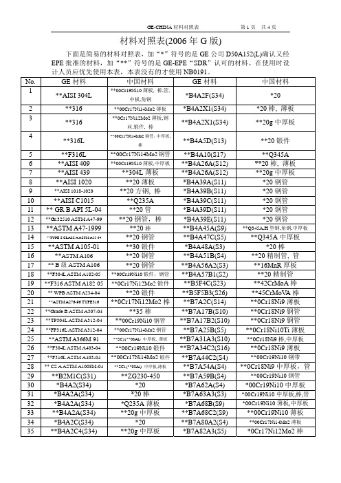
材料对照表(2006年G版)下面是简易的材料对照表,加“*”符号的是GE公司D50A152(L)确认又经EPE批准的材料,加“**”符号的是GE-EPE“SDR”认可的材料。
在使用时设计人员应优先使用本表,本表没有的才使用NB0191。
No. GE材料中国材料 GE材料中国材料1**AISI 304L **00Cr19Ni10薄板, 棒,管,*B4A2F(S34) *20中板,角钢2 **316 **00Cr17Ni14Mo2薄板*B4A2X1(S34) *20棒, 薄板3**B4A2X1(S34)**20g中厚板**316 **0Cr17Ni12Mo2薄板,钢丝,锻件,棒4**B4A5D(S13) **20锻件**316L **00Cr17Ni14Mo2钢管,中厚板,棒5 **F316L **00Cr17Ni14Mo2钢管**B4A10(S17) **Q345A409 **00Cr19Ni10薄板,中厚板**B4A26A(S12) **20棒, 薄板6 **AISI439 **304L薄板 **B4A26A(S12)**20g中厚板7 **AISI1020 **20薄板*B4A39A(S11) *20钢管8 **AISI9 **AISI 1018-1020 **20方钢, 棒 *B4A39B(S11) *20钢管C1015 **Q235A *B4A39C(S11) *20钢管10 **AISI11 ** GR B API 5L-04 **20管 *B4A39D(S11) *20钢管12 **Gr.32510 ASTM A47-99**20钢管,棒 *B4A39E(S11) *20钢管A47-1999 **20棒**B4A45A(S9) **Q345A,H型钢,角钢,中厚板13 **ASTM14 **TYPE S CLASS A ASTM A53-04 **20钢管 **B4A47C(S5) **Q345A中厚板A105-01 **30锻件 *B4A48A(S3) *20棒15 **ASTM16 **ASTM A106 **20钢管 **B4A51B(S4) **20精制管, 管17 ** B级ASTM A106 **20钢管 **B4A56A2(S3) **16MnR厚板18 **F304L ASTM A182-05 **00Cr19Ni10锻件,钢管**B4A57B1(S2) **20精制管19 **F316 ASTM A182-05**0Cr17Ni12Mo2锻件**B5F4C(S23) **42CrMoA棒20 ** WPB ASTM A234-04 **20锻件 **B5F5B3(S26) **45CrMoV A棒21 **ASTM A276-96 TYPE316 **0Cr17Ni12Mo2棒**B7A2C(S14) **0Cr18Ni9薄板**0Cr18Ni9钢管22 **Grade B ASTM A307-04**35棒 **B7A17B(S10)23 **TP304L ASTM A312-04**00Cr19Ni10钢管**B7A17B2(S10) **0Cr18Ni9钢管24 **FP316L ASTM A312-04**00Cr17Ni14Mo2钢管**B7A25B(S5) **0Cr18Ni10Ti薄板25 **ASTM A366M-91 **SC1(**08Al) 中厚板, 薄板**B7A31A3(S10) **0Cr18Ni9棒,中厚板26 **F304L ASTM A403-04 **00Cr19Ni10锻件**B7A34C2(S16) **0Cr18Ni9薄板27 **F316L ASTM A403-04 **00Cr17Ni14Mo2锻件**B7A44C2(S4) **00Cr19Ni10钢带28 ** CS A ASTM A1008M-04 **SC1(**08Al) 中厚板,薄板**B7A54A(S4) **0Cr18Ni9中厚板,管29 **B2M1C(S31) **ZG230-450 **B7A59B(S4) **00Cr19Ni10钢管30 *B4A2(S34) *20 *B7A62A(S4) *00Cr19Ni10中厚板31 *B4A2A(S34) *20棒 *B7A63A3(S3)*00Cr19Ni10中厚板,棒,管32 *B4A2A(S34)*Q235A薄板 *B7A68B(S9) *00Cr19Ni10薄板,中厚板33 **B4A2A(S34)**20g中厚板 **B7A68C2(S9) **00Cr19Ni10薄板34 *B4A2C(S34) *20 **B7A80A2(S4) **00Cr17Ni14Mo2薄板35 **B4A2C4(S34) **20g中厚板 *B7A82A3(S5) *0Cr17Ni12Mo2棒材料对照表(2006年G版)下面是简易的材料对照表,加“*”符号的是GE公司D50A152(L)确认又经EPE批准的材料,加“**”符号的是GE-EPE“SDR”认可的材料。
高精度宽范围恒流源设计

高精度宽范围恒流源设计吴茂成(苏州大学物理科学与技术学院,江苏苏州215006)摘要:设计了一种由基准电压源、集成运算放大器及复合管等组成的高精度恒流源电路,其输出电流范围为1 A~1A。
详细分析了该电路的工作原理,公式推导证明了设计的正确性,并对实际应用中元器件的选取进行了说明。
对所设计恒流源电路的性能进行了测试,测试结果表明:该电路精度高、稳定性好,输出电流精度相对误差的最大值为0.152%,输出电流稳定性误差的最大值为0.047%。
关键词:恒流源;高精度;运算放大器;反馈中图分类号:T M933 文献标识码:B文章编号:1001-1390-(2011)01-0064-03D esi gn of a H i gh-precision W i de-range Constant-current SourceWU M ao-cheng(Depart m ent o f Physics Sc i e nce and Techno logy,Soocho w Un i v ersity,Suzhou215006,Ji a ngsu,Ch i n a)A bstract:A w i d e-range high-precisi o n constant-current source i s presented,wh ic h is m a i n l y co m prised o f a vo lt age reference,so m e operational a mp lifiers and a darli n g ton transistor.The range of the circu itry s output curren t va l u e is fro m1 A to1A.The w orking pr i n ciple o f the designed constant-current circu itry is ana l y zed i n details and deduced m athe m atica lly,and the se lective ru les o f the practica l e le m ents are ill u m i n ated.The perfor m ance o f the designed con stant-current source is tested,and the resu lts i n dicate t h at the circu itry cou l d generate a high-prec ision steady cur ren.t The m ax i m al re lati v e error of precisi o n and m ax i m al error o f stab ility of the ou t p ut current are0.152%and0. 047%respecti v e l y.K ey words:constant-current source,h i g h-prec ision,operati o na l a m plifier,feedback0 引 言恒流源是指能够向负载提供恒定电流的电源,在金属薄膜电阻率测量、金属丝杨氏模量测量、磁阻效应、光电效应以及光电池特性测量等大学物理实验中应用广泛。
杰斯沃尔德汽车零件说明书
K760 Cut-n-BreakReservdelarSpare partsErsatzteilePieces de rechangePiezas de repuestoRicambiPeças sobresselente575 66 02-01 HUSQV ARNA CONSTRUCTION PRODUCTSNo.Pos.Description No.Pos.Description501 00 88-01B SCREW501 00 88-02B SCREW ASSY501 27 08-01C GUIDE BUSHING501 37 13-01F LID501 37 56-01K FLYWHEEL501 48 54-02K SPARK PLUG CAP501 63 48-01K SPRING501 67 32-03K PAWL501 98 10-20J SCREW502 28 92-03C DRIVING PULLEY ASSY 502 29 50-02E CRANKSHAFT ASSY503 12 79-01J STARTER HANDLE503 16 40-01F TANK VENT503 20 34-19C SCREW503 21 27-16G SCREW503 21 28-10AFJK SCREW503 21 45-16F SCREW503 21 46-01G SCREW503 21 53-10AHM SCREW503 21 53-16CDG SCREW503 21 53-20KM SCREW503 21 53-21L SCREW503 21 53-25D SCREW503 21 53-40DH SCREW503 21 53-41C SCREW503 21 53-56DGM SCREW503 21 54-20FH SCREW503 22 10-11K NUT503 22 65-04CDFM NUT503 23 00-42K WASHER STEEL503 23 00-70C WASHER503 23 01-01K WASHER STEEL503 23 04-01C WASHER503 23 04-02D WASHER503 23 04-03B WASHER503 23 51-09K SPARK PLUG503 25 56-01DE NEEDLE BEARING503 26 02-04CDMP SEALING RING503 26 30-08A O-RING503 26 60-03H COUPLING503 26 60-04H COUPLING503 28 90-47D PISTON RING503 40 06-09M IMPULSE HOSE503 47 96-01N SCREW503 48 00-01N PIN RETAINING SCREW 503 48 11-01N PIECE503 48 18-01N SCREW503 53 56-01N PLUG WELCH503 53 57-01N STRAINER503 55 22-01D PLUG503 57 89-01F TANK CAP HOLDER503 61 66-01N GASKET PUMP503 71 53-01D DECOMPRESSION VALVE 503 74 43-01C CLUTCH SPRING503 74 44-06C CLUTCH ASSY503 84 61-01C BUFFER503 93 66-01F PRIMER HOUSING504 35 72-01F SINTER PLUG504 87 52-01A SEALING504 90 94-10C SCREW505 09 55-03H HOSE KIT505 10 35-01H O-RING505 19 52-01F FUEL HOSE505 22 09-37C BAR BOLT505 25 96-01D MUFFLER MOUNTING KIT 505 27 75-16K ISOLERHATT505 42 45-01D VIB.INSULATOR506 00 69-01K SCREW506 09 56-05A HOSE CLAMP506 22 28-02F THROTTLE LOCKOUT 506 25 30-01J COMPRESSION SPRING 506 25 59-03F TANK CAP ASSY506 25 81-02J STARTER PULLEY506 25 89-01J RECOIL SPRING506 26 22-02G WHEEL506 26 31-01J SPACING SLEEVE506 26 41-01F FUEL FILTER506 26 41-11F FUEL FILTER506 27 11-01F HOSE CLAMP506 29 21-01F GASKET506 29 88-01H FILTER506 31 30-01F LABEL506 31 69-01C DUST COVER506 31 86-02F STOP SWITCH506 31 86-02K STOP SWITCH506 33 56-15J STARTER CORD506 33 56-50J STARTER CORD506 35 27-02A PROTECTIVE SPRING 506 36 42-04D MUFFLER506 36 88-01D BRACKET506 36 97-01M INLET PIPE506 36 98-01M INLET PIPE506 37 02-01L COVER506 37 04-01L BELLOWS506 37 05-01M FLANGE INLET PIPE506 37 06-01M FLANGE INLET PIPE506 37 11-03H FRONT HANDLE506 37 13-01F THROTTLE ROD506 37 19-02F BASE PLATE506 37 20-03F THROTTLE TRIGGER506 37 24-01D PISTON ASSY506 37 27-02A BELT506 37 58-02D COOLING PLATE506 37 67-01CDMP GASKET CYLINDER BASE 506 37 68-03CDMP GASKET CARBURETTOR 506 37 69-02CDMP GASKET MUFFLER506 37 69-02CDMP GASKET MUFFLER506 37 70-03CDMP GASKET CRANCASE506 37 72-02H SPRING RETAINER506 37 80-01F GROMMET506 37 84-02K CABLE506 37 85-01K CABLE506 37 95-01F SPRING506 38 15-01F HEAT SHIELD506 38 26-01P COMBINATION TOOL506 38 53-05CDMP GASKET KIT506 38 60-05H VALVE ASSY506 38 65-08F FUEL TANK506 38 65-12F FUEL TANK506 38 66-01F TANK VENT ASSY506 38 67-02F GROUND SUPPORT506 38 71-02H STOP506 38 78-34K IGNITION CABLE506 39 46-02F CAP506 39 54-01N COLLAR506 39 55-01N COVER506 39 56-01N COVER506 39 57-01N DIAPHRAGM ASSY506 39 58-01N GASKET506 39 60-01N DIAPHRAGM PUMP506 39 61-01N NOZZLE ASSY506 39 62-01N GASKET506 39 64-01N QUAD RING506 39 65-01N ROD506 39 66-01N SCREW506 39 69-01N SCREW506 39 70-01N SCREW506 39 71-01N SHAFT ASSY506 39 72-01N SCREW506 39 73-01N SHAFT ASSY CHOKENo.Pos.Description506 39 74-01N SHAFT ASSY506 39 75-01N SPRING506 39 78-01N VALVE506 39 79-01N WASHER506 39 84-05L CYLINDER COVER ASSY 506 39 90-01N O-RING506 39 91-01N PLUG506 40 24-01B CENTER NUT506 40 25-02B SCREW506 40 26-01C SCREW506 40 28-02A BEARING CAGE506 40 29-02A BUSHING506 40 33-01C BELT TENSIONER506 40 37-01G BUSHING506 40 46-02A WEAR PROTECTION 506 40 51-01A STOP506 40 53-01A BAR PLATE506 40 55-02A BELT GUARD506 40 56-01A DEFLECTION LIMITER 506 40 56-02A DEFLECTION LIMITER 506 40 57-02A GROMMET506 40 60-01G SPRING506 40 61-01A SPRING506 40 61-02A SPRING506 40 63-02G SPRAY GUARD506 40 64-03A BELT GUARD506 40 65-02A BLADE GUARD506 40 98-02A NIPPLE506 40 99-01N GASKET KIT506 41 00-03N GASKET KIT CARB506 41 23-01CDMP GASKET506 49 87-02H HOSE CLAMP510 00 08-01J SEALING HOLDER510 00 72-01G SPRAY GUARD UPPER 510 00 73-01G GUIDE PIECE510 05 66-01G SPRAY GUARD ASSY 510 11 56-02K IGNITION MODULE510 18 12-02MN CARBURETTOR510 20 20-01G WASHER510 20 24-01G BAND510 26 92-22J SCREW520 75 73-04D CYLINDER ASSY522 03 81-01G LABEL522 47 48-01C WASHER522 47 57-01C SPRING RETAINER522 60 75-01N VALVE522 83 23-01H GROUND SUPPORT522 83 24-01H GROUND SUPPORT525 44 43-01L FILTER COVER525 44 60-01J STARTER COVER525 47 06-01M AIR FILTER PAPER525 56 45-01A BELT COVER525 57 11-01J LABEL525 58 43-01L AIR NOZZLE525 61 70-02L SEALING525 62 39-01C CLUTCH COVER525 73 98-01G HOLDER525 76 35-02L DECAL525 83 18-01C BALL BEARING537 01 25-01N BALL537 01 26-01N SPRING537 04 24-14F FUEL HOSE537 17 62-01N VALVE537 17 64-01N LEVER537 17 70-01N VALVE537 17 78-01N PLUG537 20 33-01E CUP537 21 03-07F VIBRATION ABSORBER 537 38 51-01N SCREW537 38 52-01N E-CLIP 544 03 21-01G SPRAY GUARD544 03 22-01G PLATE544 03 92-01G BUSHING544 04 17-01A HOSE544 06 12-01DFH SCREW544 08 21-01N SCREW544 08 22-01N SCREW544 10 37-03A BAR ASSY544 10 50-04A HOSE ASSY544 10 59-01A BEARING544 17 80-02P TOOL544 17 81-01P PULLER544 21 93-02CDMP INSERT544 22 90-02F CHOKE CONTROL544 23 82-01F BAND544 26 53-01B WASHER544 32 50-03F FUEL HOSE544 35 26-01M PLATE544 37 44-02A LABEL544 38 39-01J AIR CONDUCTOR544 39 32-01F HOSE CLIP544 83 64-01N PUMP COVER544 83 65-01N SPRING544 89 09-02L LABEL574 23 14-01L DECAL574 23 14-02L DECAL574 23 16-01L DECAL574 23 16-02L DECAL574 23 16-03L DECAL574 24 09-01C PAWL574 36 20-01J STARTER574 36 21-01L FILTER HOLDER ASSY 574 36 23-01M FILTER574 47 48-02C CRANK CASE ASSY574 48 96-01C LABEL574 83 62-01B CUTTING BLADE574 83 62-02B CUTTING BLADE574 83 62-03B CUTTING BLADE575 27 99-01A CUTTER ARM575 30 31-01H HOSE ASSY575 33 81-01C BELT TENSIONER ASSY 575 34 85-01G SPRAY GUARD ASSY575 35 13-01H HANDLE575 35 40-01M CARBURETTOR BRACKET 575 44 13-01N SPRING575 51 62-01H HOSE ASSY720 12 40-20F PARALLEL PIN724 12 84-01A SCREW731 23 18-01C NUT732 21 14-01G LOCK NUT734 48 80-01G WASHER735 31 08-20C CIRCLIP735 31 10-41B CIRCLIP737 43 12-00D CIRCLIP738 22 02-25CE BALL BEARING740 42 05-00G O-RING740 43 13-00J O-RINGNo.Pos.DescriptionPage AK760 Cut-N-BreakPos.Part No.Description Quantity Notes New Part 1575 27 99-01CUTTER ARM1Incl. 2, 9 - 16, 21 - 282544 10 50-04HOSE ASSY1Incl. 3 - 83504 87 52-01SEALING14544 04 17-01HOSE15506 40 57-02GROMMET16506 35 27-02PROTECTIVE SPRING17506 09 56-05HOSE CLAMP18506 40 98-02NIPPLE19506 40 55-02BELT GUARD110503 26 30-08O-RING211506 40 64-03BELT GUARD112506 40 61-01SPRING113525 56 45-01BELT COVER114503 21 53-10SCREW615506 40 56-01DEFLECTION LIMITER116544 10 37-03BAR ASSY1Incl. 17 - 2017506 40 28-02BEARING CAGE118544 10 59-01BEARING119506 40 29-02BUSHING120506 40 53-01BAR PLATE121506 37 27-02BELT122506 40 65-02BLADE GUARD123506 40 61-02SPRING124506 40 46-02WEAR PROTECTION125503 21 28-10SCREW126506 40 51-01STOP127724 12 84-01SCREW128506 40 56-02DEFLECTION LIMITER129544 37 44-02LABEL1K760 Cut-n-Breakmodel_enhet_yyyy-mm345688271BPage BK760 Cut-N-BreakPos.Part No.Description Quantity Notes New Part 1501 00 88-02SCREW ASSY1Incl. 2, 72501 00 88-01SCREW13506 40 25-02SCREW14503 23 04-03WASHER15544 26 53-01WASHER16735 31 10-41CIRCLIP17506 40 24-01CENTER NUT18574 83 62-01CUTTING BLADE2EL10 CnB Soft8574 83 62-02CUTTING BLADE2EL35 CnB Medium8574 83 62-03CUTTING BLADE2EL70 CnB HardPage CK760 Cut-N-BreakPos.t r a esDo i t p i r cNPt r aQ.onNuwPseay t i t nNe t o1731 23 18-01NUT22503 20 34-19SCREW13575 33 81-01BELT TENSIONER ASSY1Incl. 4 - 104525 62 39-01CLUTCH COVER15503 23 04-01WASHER26574 24 09-01PAWL17735 31 08-20CIRCLIP18506 40 26-01SCREW19506 40 33-01BELT TENSIONER110504 90 94-10SCREW211574 48 96-01LABEL112503 74 44-06CLUTCH ASSY1Incl. 1313503 74 43-01CLUTCH SPRING114502 28 92-03DRIVING PULLEY ASSY1Incl. 15 - 1715503 23 00-70WASHER116525 83 18-01BALL BEARING217506 31 69-01DUST COVER118574 47 48-02CRANK CASE ASSY1Incl. 19 - 2919506 38 53-05GASKET KIT1Incl. 24, 27, 30 - 3520503 21 53-16SCREW221522 47 48-01WASHER122522 47 57-01SPRING RETAINER123503 21 53-41SCREW624503 26 02-04SEALING RING225501 27 08-01GUIDE BUSHING226738 22 02-25BALL BEARING227506 37 70-02GASKET CRANKCASE128503 84 61-01BUFFER129505 22 09-37BAR BOLT230503 22 65-04NUT131506 41 23-01GASKET132506 37 69-02GASKET MUFFLER133506 37 70-03GASKET CRANKCASE134544 21 93-02INSERT135506 37 67-01CYLINDER BASE GASKET136506 37 68-03GASKET CARBURETTOR1K760 Cut-N-BreakPos.Part No.Description Quantity Notes New Part 1505 42 45-01VIB.INSULATOR12544 06 12-01SCREW13503 71 53-01DECOMPRESSION VALVE14503 55 22-01PLUG15503 21 53-25SCREW56520 75 73-04CYLINDER ASSY1Incl. 7 - 117503 21 53-16SCREW28506 36 88-01BRACKET19506 37 67-01CYLINDER BASE GASKET110506 37 24-01PISTON ASSY1Incl. 12 - 1311503 25 56-01NEEDLE BEARING112503 28 90-47PISTON RING213737 43 12-00CIRCLIP214506 41 23-01GASKET115506 37 58-02COOLING PLATE116506 37 69-02GASKET MUFFLER117506 36 42-04MUFFLER118503 21 53-40SCREW219503 21 53-56SCREW120503 23 04-02WASHER121503 22 65-04NUT122506 38 53-05GASKET KIT1Incl. 9, 14, 16, 24 - 2823505 25 96-01MUFFLER MOUNTING KIT1Incl. 5, 14, 16, 18 - 2124506 37 70-02GASKET CRANKCASE125506 37 70-03GASKET CRANKCASE126544 21 93-02INSERT127503 26 02-04SEALING RING228506 37 68-03GASKET CARBURETTOR1124332K760 Cut-N-BreakPos.Part No.Description Quantity Notes New Part 1502 29 50-02CRANKSHAFT ASSY1Incl. 2 - 42738 22 02-25BALL BEARING23537 20 33-01CUP24503 25 56-01NEEDLE BEARING1K760 Cut-N-BreakPos.Part No.Description Quantity Notes New Part 1506 38 65-08FUEL TANK1Incl. 2 - 4, 6 - 7, 10 - 16, Purge1506 38 65-12FUEL TANK1Incl. 2 - 4, 6 - 7, 10 - 162720 12 40-20PARALLEL PIN23506 22 28-02THROTTLE LOCKOUT14506 37 95-01SPRING15506 37 13-01THROTTLE ROD16506 37 20-03THROTTLE TRIGGER17506 38 66-01TANK VENT ASSY1Incl. 8 - 98504 35 72-01SINTER PLUG19503 16 40-01TANK VENT110544 39 32-01HOSE CLIP111501 37 13-01LID112503 22 65-04NUT613506 38 67-02GROUND SUPPORT114503 21 45-16SCREW215544 32 50-03FUEL HOSE116506 26 41-11FUEL FILTER1Incl. 17 - 1817506 27 11-01HOSE CLAMP118506 26 41-01FUEL FILTER119544 22 90-02CHOKE CONTROL120506 37 80-01GROMMET121503 21 28-10SCREW122506 31 86-02STOP SWITCH123503 93 66-01PRIMER HOUSING1Purge24505 19 52-01FUEL HOSE1Purge25537 04 24-14FUEL HOSE1Purge26506 25 59-03TANK CAP ASSY1Incl. 27 - 2827506 29 21-01GASKET128503 57 89-01TANK CAP HOLDER129506 39 46-02CAP130506 38 15-01HEAT SHIELD131503 21 54-20SCREW432506 37 19-02BASE PLATE133537 21 03-07VIBRATION ABSORBER1Incl. 34 - 3534544 06 12-01SCREW135544 23 82-01BAND136506 31 30-01LABEL1Japan onlyK760 Cut-N-BreakPos.Part No.Description Quantity Notes New Part 1575 34 85-01SPRAY GUARD ASSY1Incl. 2 - 13, 222503 21 53-56SCREW13506 40 60-01SPRING14506 40 63-02SPRAY GUARD15740 42 05-00O-RING26506 40 37-01BUSHING17732 21 14-01LOCK NUT18525 73 98-01HOLDER19544 03 21-01SPRAY GUARD110503 21 53-16SCREW211544 03 22-01PLATE112544 03 92-01BUSHING213510 05 66-01SPRAY GUARD ASSY1Incl. 14 - 2114510 00 72-01SPRAY GUARD UPPER115510 00 73-01GUIDE PIECE116503 21 46-01SCREW217734 48 80-01WASHER218506 26 22-02WHEEL219510 20 24-01BAND120510 20 20-01WASHER221503 21 27-16SCREW422522 03 81-01LABEL11016666151817 1413131211627845319K760 Cut-N-BreakPos.Part No.Description Quantity Notes New Part 1505 09 55-03HOSE KIT1Incl. 2 - 32575 51 62-01HOSE ASSY1Incl. 4 - 5, 7 - 83506 38 60-05VALVE ASSY1Incl. 74506 49 87-02HOSE CLAMP15575 30 31-01HOSE ASSY16503 21 54-20SCREW87506 29 88-01FILTER18505 10 35-01O-RING19503 26 60-03COUPLING1USA, Canada9503 26 60-04COUPLING110544 06 12-01SCREW311506 37 72-02SPRING RETAINER112522 83 23-01GROUND SUPPORT113503 21 53-10SCREW214503 21 53-40SCREW115522 83 24-01GROUND SUPPORT116575 35 13-01HANDLE1Incl. 6, 17 - 1817506 37 11-03FRONT HANDLE118506 38 71-02STOP1Page JK760 Cut-N-BreakPos.Part No.Description Quantity Notes New Part 1574 36 20-01STARTER1Incl. 2 - 152510 26 92-22SCREW13740 43 13-00O-RING14510 00 08-01SEALING HOLDER15506 26 31-01SPACING SLEEVE16506 25 30-01COMPRESSION SPRING17506 25 81-02STARTER PULLEY18503 21 28-10SCREW29506 25 89-01RECOIL SPRING110506 33 56-15STARTER CORD110506 33 56-50STARTER CORD150 m11503 12 79-01STARTER HANDLE112525 44 60-01STARTER COVER113501 98 10-20SCREW414525 57 11-01LABEL115544 38 39-01AIR CONDUCTOR1K760 Cut-n-Break14131231101211659416171587KPage KK760 Cut-N-BreakPos.Part No.Description Quantity Notes New Part 1503 21 28-10SCREW22506 31 86-02STOP SWITCH13506 37 84-02CABLE14503 23 51-09SPARK PLUG1RCJ 6 Y5510 11 56-02IGNITION MODULE1Incl. 6 - 86501 48 54-02SPARK PLUG CAP17506 38 78-34IGNITION CABLE18505 27 75-16ISOLERHATT19503 21 53-20SCREW210506 37 85-01CABLE111503 23 01-01WASHER STEEL112503 22 10-11NUT113501 37 56-01FLYWHEEL1Incl. 14 - 1714503 23 00-42WASHER STEEL215501 63 48-01SPRING216501 67 32-03PAWL217506 00 69-01SCREW2Page LK760 Cut-N-BreakPos.Part No.Description Quantity Notes New Part 1503 21 53-21SCREW102525 76 35-02DECAL13525 44 43-01FILTER COVER14574 23 14-01DECAL1EPA USA4574 23 14-02DECAL1CE, EPA Canada5574 36 21-01FILTER HOLDER ASSY1Incl. 66525 61 70-02SEALING17506 39 84-05CYLINDER COVER ASSY1Incl. 88544 89 09-02LABEL19574 23 16-01DECAL19574 23 16-02DECAL1Rescue9574 23 16-03DECAL1Oil Guard10506 37 02-01COVER111506 37 04-01BELLOWS112525 58 43-01AIR NOZZLE1Page MK760 Cut-N-BreakPos.Part No.Description Quantity Notes New Part 1506 38 53-05GASKET KIT1Incl. 2 - 8, 232506 41 23-01GASKET13506 37 69-02GASKET MUFFLER14506 37 70-02GASKET CRANKCASE15506 37 70-03GASKET CRANKCASE16544 21 93-02INSERT17503 26 02-04SEALING RING28506 37 67-01CYLINDER BASE GASKET19574 36 23-01FILTER1Incl. 1010525 47 06-01AIR FILTER PAPER111575 35 40-01CARBURETTOR BRACKET1Incl. 1212503 22 65-04NUT413503 21 53-10SCREW214506 37 06-01FLANGE INLET PIPE115506 36 98-01INLET PIPE116503 21 53-20SCREW117506 37 05-01FLANGE INLET PIPE118506 36 97-01INLET PIPE119503 40 06-09IMPULSE HOSE120544 35 26-01PLATE121503 21 53-56SCREW222510 18 12-02CARBURETTOR1Zama C3-EL43A23506 37 68-03GASKET CARBURETTOR1Page NK760 Cut-N-BreakPos.t r a enDo i t p i r cNPt r aQ.osNewPse t oay t i t nNu1510 18 12-02CARBURETTOR1Zama C3-EL43A, Incl. 2 - 432503 47 96-01SCREW13544 83 64-01PUMP COVER14503 61 66-01GASKET PUMP15506 39 60-01DIAPHRAGM PUMP16506 39 65-01ROD17544 08 22-01SCREW29506 39 71-01SHAFT ASSY110506 39 75-01SPRING111506 39 54-01COLLAR212506 39 64-01QUAD RING413506 39 73-01SHAFT ASSY CHOKE114506 39 90-01O-RING115503 48 18-01SCREW116506 39 78-01VALVE117537 17 70-01VALVE118522 60 75-01VALVE1Japan only19506 39 74-01SHAFT ASSY120503 53 57-01STRAINER121506 39 58-01GASKET122503 48 11-01PIECE123537 01 26-01SPRING124537 01 25-01BALL125544 83 65-01SPRING126506 39 72-01SCREW127506 39 70-01SCREW128506 39 69-01SCREW129537 38 51-01SCREW230506 39 79-01WASHER231537 38 52-01E-CLIP232506 39 91-01PLUG133506 39 61-01NOZZLE ASSY134503 53 56-01PLUG WELCH135537 17 78-01PLUG136537 17 62-01VALVE137575 44 13-01SPRING138537 17 64-01LEVER139544 08 21-01SCREW140503 48 00-01PIN RETAINING SCREW141506 39 62-01GASKET242506 39 57-01DIAPHRAGM ASSY143506 39 55-01COVER144506 39 56-01COVER145506 39 66-01SCREW446506 40 99-01GASKET KIT1Incl. 4-5, 21, 41, 4247506 41 00-03GASKET KIT CARB1Incl. 4-5, 12, 14, 20, 21, 34-38, 40-42Page PK760 Cut-N-BreakPos.Part No.Description Quantity Notes New Part 1544 17 80-02TOOL12506 38 26-01COMBINATION TOOL13544 17 81-01PULLER14506 38 53-05GASKET KIT1Incl. 5 - 125506 41 23-01GASKET16506 37 69-02GASKET MUFFLER17506 37 70-02GASKET CRANKCASE18506 37 70-03GASKET CRANKCASE19544 21 93-02INSERT110503 26 02-04SEALING RING211506 37 67-01CYLINDER BASE GASKET112506 37 68-03GASKET CARBURETTOR1。
瑞士兰吉尔电度表

H 71 0200 0215 g en
修订情况
索引 a b c
d e f g
日期 2002 年 12 月 20 日 2003 年 1 月 7 日 2003 年 3 月 7 日
2003 年 3 月 19 日 2003 年 6 月 30 日 2003 年 12 月 19 日 2004 年 3 月 31 日
H 71 0200 0215 g en- Z.Q 高精度电子关口表–用户手册
3.1 3.2 3.3 3.4 3.5 3.6 3.7 3.8 3.9 3.10 3.10.1 3.10.2 3.10.3 3.11 4 4.1 4.2 4.2.1 4.2.2 4.2.3 4.3 4.3.1 4.3.2 4.3.3 4.4 4.4.1 4.4.2 4.4.3 4.5 4.6 4.6.1 4.7 4.7.1 5 5.1 5.1.1
兰吉尔 2/76
安全_____________________________________________________________ 6 安全信息 _________________________________________________________ 6 责任_____________________________________________________________ 6 安全规则 _________________________________________________________ 7 单元概述_________________________________________________________ 9 应用_____________________________________________________________ 9 特性_____________________________________________________________ 9 型号说明 ________________________________________________________ 10 方框图 __________________________________________________________ 11 测量系统 ________________________________________________________ 12 输入信号 ________________________________________________________ 12 输入电路 ________________________________________________________ 13 模数转换器 ______________________________________________________ 13 信号处理器 ______________________________________________________ 13 微处理器 ________________________________________________________ 14 微处理器提供的数据 ______________________________________________ 14 测量参数的计算 __________________________________________________ 16 费率控制 ________________________________________________________ 17 日历钟 __________________________________________________________ 18 同步和时间设置 __________________________________________________ 18 通过同步脉冲使日历钟同步 ________________________________________ 19 通过通信使日历钟同步 ____________________________________________ 20 时间设置 ________________________________________________________ 20 处理偏差 ________________________________________________________ 20 寄存器 __________________________________________________________ 21 存储器 __________________________________________________________ 21 负荷曲线 ________________________________________________________ 21 事件日志 ________________________________________________________ 22 供电____________________________________________________________ 22 辅助电源 ________________________________________________________ 22 传送接点模块 ____________________________________________________ 22 通信单元(可选择) ______________________________________________ 22 软件工具 ________________________________________________________ 23 结构描述________________________________________________________ 24
RYII中文资料
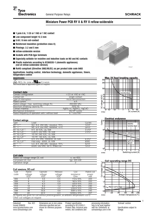
1Datasheet Rev. HC1 Issued 2008/03 Dimensions are in mm unlessotherwise specified and areshown for reference purposesProduct specificationaccording to IEC61810-1.Product data, technical para-processing informationonly to be used togetherwith the'Definitions' at‘Schrack’ section.Specifications subject toEspecially suitable for resistive and inductive loads on NO and NC contactsRoHS compliant (Directive 2002/95/EC) as per product date code 0403Applications: heating control, interface technology, domestic appliances, timers,V REG.-Nr. 5358, Z E214025Contact dataContact configuration 1 CO or 1NO or 1NCContact set single contactType of interruption micro disconnectionRated current8ARated voltage/max. switching voltage AC250/400VACMaximum breaking capacity AC2000VAContact material AgNi0,15, AgSnO2, AgCdOMechanical endurance30x106cyclesRated frequency of operation with/without load 6 / 1200min-1Contact ratingsType Load CyclesRY**1***NO, 8 A, 250 VAC, resistive, 70°C1x105RY**1***NC, 8 A, 250 VAC, resistive, 70°C5x104RY**(0,1,2)***8 A, 30 VDC, UL 5083x104RY**(0,1,2)***0,28 A, 250 VDC, UL 5083x104RY**(0,1,2)***1/2 HP, 240 VDC, UL 508RY**(0,1,2)***1/4 HP, 120 VDC, UL 508RY**(0)***8 A, 415 VAC, resistive, UL 5086x103RY**(0,1,2)***Pilot duty - B300, UL 5086000RY*** ***CO, 8 A, 250 VAC, resistive, 70°C5x103RY**1 ***6(4)A, 250 VAC, 85°C, EN607301x105Coil dataRated coil voltage range DC coil 5...60VDCCoil power DC coil typ. 220mWOperative range2Coil versions,DC-coilCoil Rated Operate Release Coil Rated coilcode voltage voltage voltage resistance powerVDC VDC VDC Ohm mW00553,50,5112+10%22300664,20,6162+10%22200996,30,9320+10%253012128,41,2627+10%2300242416,82,42350+10%2450484833,64,89391+10%2450606042,06,014000+10%257All figures are given for coil without preenergization, at ambient temperature +23°COther coil voltages on requestF0142-FInsulation CO contact NO contact Dielectric strength coil-contact circuit5000V effopen contact circuit1000V effClearance/creepage coil-contact circuit W8 / 8mmMaterial group of insulation parts IIIaTracking index of relay base PTI250, PTI 175* Type of insulation coil-contact circuit reinforcedopen contact circuit functionalRated insulation voltage250V250VPollution degree 3 23Rated voltage system230V 400V230 / 400VOvervoltage category III IIIOther dataRoHS - Directive 2002/95/EC compliant as per product date code 0403 Flammability class according to UL94V-0GWT to IEC 60335-1> 750 °C**Ambient temperature range -40...+70°CAmbient temperature max.85°C at 6AOperate- / release time typ. 7 / 3msBounce time NO / NC contact typ. 2.5 / 4.5ms Vibration resistance (function) NO/NC contact20 / 5gShock resistance (function) NO/NC contact20 / 5gShock resistance (destruction) 100gCategory of protection RTII-flux proof, RTIII- wash tight** Mounting pcbMounting position anyMinimum mounting distance W 0mmSoldering heat resistance flux proof version270°C/10swash tight version260°C/5sRelay weight8gPackaging unit20 / 500pcs AccessoiresFor technical details see datasheet Accessoires RYII* reflow-solderable version** not as reflow-solderable version PCB layout / terminal assignment Bottom view on solder pins1 NO, 1 NC contact 5mmS0254-AAS0254-ABS0254-ACS0254-ADS0254-AFS0254-AEDimensionsPinning 3.2mmPinning 5mmSoldering profile for reflow-solderable version。
- 1、下载文档前请自行甄别文档内容的完整性,平台不提供额外的编辑、内容补充、找答案等附加服务。
- 2、"仅部分预览"的文档,不可在线预览部分如存在完整性等问题,可反馈申请退款(可完整预览的文档不适用该条件!)。
- 3、如文档侵犯您的权益,请联系客服反馈,我们会尽快为您处理(人工客服工作时间:9:00-18:30)。
元器件交易网
REF19x Series
TABLE OF CONTENTS
Specifications..................................................................................... 3 Electrical Characteristics—REF191 @ TA = 25°C .................... 3 Electrical Characteristics—REF191 @ −40°C ≤ TA ≤ +85°C .. 4 Electrical Characteristics—REF191 @ −40°C ≤ TA ≤+125°C. 5 Electrical Characteristics—REF192 @ TA = 25°C .................... 5 Electrical Characteristics—REF192 @ −40°C ≤ TA ≤ +85°C.. 6 Electrical Characteristics—REF192 @ −40°C ≤ TA ≤ +125°C 6 Electrical Characteristics—REF193 @ TA = 25°C .................... 7 Electrical Characteristics—REF193 @ −40°C ≤ TA ≤ +85°C.. 7 Electrical Characteristics—REF193 @ TA ≤ −40°C ≤ +125°C 8 Electrical Characteristics—REF194 @ Ta = 25°C..................... 8 Electrical Characteristics—REF194 @ −40°C ≤ TA ≤ +85°C.. 9 Electrical Characteristics—REF194 @ −40°C ≤ TA ≤ +125°C 9 Electrical Characteristics—REF195 @ TA = 25°C .................. 10 Electrical Characteristics—REF195 @ −40°C ≤ TA ≤ +85°C 10 Electrical Characteristics—REF195 @ −40°C ≤ TA ≤ +125°C ....................................................................................................... 11 Electrical Characteristics—REF196 @ TA = 25°C .................. 11 Electrical Characteristics—REF196 @ −40°C ≤ TA ≤ +85°C 12 Electrical Characteristics—REF196 @ −40°C ≤ TA ≤ +125°C ....................................................................................................... 12 Electrical Characteristics—REF198 @ TA = 25°C .................. 13 Electrical Characteristics—REF198 @ −40°C ≤ TA ≤ +85°C 13 Electrical Characteristics—REF198 @ −40°C ≤ TA ≤ +125°C ....................................................................................................... 14
TP 1 REF19x 8 NC VS 2 SERIES 7 NC
SLEEP 3 TOP VIEW 6 OUTPUT GND 4 (Not to Scale) 5 TP
NOTES 1. NC = NO CONNECT. 2. TP PINS ARE FACTORY TEST
POINTS, NO USER CONNECTION.
APPLICATIONS
Portable instruments ADCs and DACs Smart sensors Solar-powered applications Loop current-powered instruments
GENERAL DESCRIPTION
The REF19x series precision band gap voltage references use a patented temperature drift curvature correction circuit and laser trimming of highly stable, thin-film resistors to achieve a very low temperature coefficient and high initial accuracy.
All electrical grades are available in an 8-lead SOIC_N package; the PDIP and TSSOP packages are available only in the lowest electrical grade. Products are also available in die form.
Figure 1. 8-Lead SOIC_N and TSSOP Pin Configuration (S Suffix and RU Suffix)
00371-001
TP 1 VS 2
ห้องสมุดไป่ตู้
REF19x SERIES
8 NC 7 NC
SLEEP 3 TOP VIEW 6 OUTPUT
GND 4 (Not to Scale) 5 TP
REVISION HISTORY
9/06—Rev. H to Rev. I Updated Format..................................................................Universal Changes to Table 25 ....................................................................... 15 Changes to Figure 6........................................................................ 16 Changes to Figure 10, Figure 12, Figure 14, and Figure 16....... 17 Changes to Figure 18...................................................................... 18 Changes to Figure 20...................................................................... 19 Changes to Figure 23...................................................................... 20 Changes to Figure 25...................................................................... 21 Updated Outline Dimensions ....................................................... 25 Changes to Ordering Guide .......................................................... 26 6/05—Rev. G to Rev. H Updated Format..................................................................Universal Changes to Caption in Figure 7 .................................................... 16 Updated Outline Dimensions ....................................................... 25 Changes to Ordering Guide .......................................................... 26
TEST PINS
Test Pin 1 and Test Pin 5 are reserved for in-package Zener zap. To achieve the highest level of accuracy at the output, the Zener zapping technique is used to trim the output voltage. Since each unit may require a different amount of adjustment, the resistance value at the test pins varies widely from pin to pin and from part to part. The user should leave Pin 1 and Pin 5 unconnected.