FS8853-18PV中文资料
HYDAC流控制阀门产品参数手册说明书

Flow Control ValvesDRV & DRVP Series (see page 47)Check ValvesRV & RVP Series (see page 53)Needle ValvesDV, DVE & DVP Series (see page 43)Pressure Compensated Flow Control ValvesSRVR Series (see page 51)Stainless Steel Flow Control ValvesDV, DRV & RV Series(see page 55)OverviewProduct Features• Phosphate coated steel valve body • FPM (Fluoroelastomer) seals• Slotted control spindle for precise and linear flow adjustments • Exclusive safety spindle design• Color coded spindle for accurate flow control•Guided poppets for smoother, chatter free operationAvailable Options• Panel mounting kit• 25 and 65 PSI cracking pressure springs (7 psi standard)• Zinc Plated Body. Consult HYDAC for price and deliveryIntroductionOur complete line of flow control valves are designed and manufactured by our ISO 9001 certified FLUTEC Division.Description• T he HYDAC family of flow control valves permit safe, simple and repeatable control of hydraulic fluids at operating pressures to 5000 psi.• T he standard slotted control spindle allows for a wide range of infinitely variable flow adjustments with excellent flow characteristics.• P recise adjustment of flow is achieved by a micrometer style adjustment knob featuring a color coded flow indicator for accurate, easy-to read visual flow reference.• D esign modifications and special materials are available for corrosive fluids such as phosphate ester, acids and caustics.Valve DesignHYDAC flow control valves can be adjusted easily and precisely by means of the control knob. Increasing the number of turns from the fully closed position provides a steady increase of the flow rate. The colored scale permits accurate repetition of settings and the colored triangle on the rising spindle provides a visual indication of the increasing cross section of the flow area. A set screw on the side locks the knob at the desired setting.HYDAC flow control valves include a unique safety spindle design feature. As the valve spindle is turned counter-clockwise, the spindle shoulder will engage the safety screw limiting the travel of thespindle. The hardened, high-strength steel safety screw is sealed in position to discourage tampering.Flow Control Valve Design Features and OptionsGuided PoppetA BDV, DVE, & DVP SeriesNeedle ValvesModel CodeDV - 06 - 01 .X / 5 - S - MNeedle Valve DV = Inline Mounting DVP = Manifold Mounting DVE = Cartridge ValveNominal Sizes DV & DVP SAE (DV only) NPT F (DV Only) BSPP (DV Only)Nom. Size Tube Size Thread Size Pipe Size Pipe OD Thread Size 06 = 1/8” 0.405” G1/8 08 = -4 7/16-20 UNF 1/4” 0.540” G1/4 10 = -6 9/16-18 UNF 3/8” 0.675” G3/8 12 = -8 3/4-16 UNF 1/2” 0.840” G1/2 16 = -12 1-1/16-12 UN 3/4” 1.050” G3/4 20 = -16 1-5/16-12 UN 1” 1.315” G1 25 = -20 1-5/8-12 UN 1-1/4” 1.660” G1 1/4 30 = -24 1-7/8-12 UN 1-1/2” 1.900G1 1/2DVENom Size SAE CavityBSPP Cavity 08 = 3/4-16 UNF G1/2 10 = 7/8-14 UNF G1/2 12 = 1-1/16-12 UN G3/4 16 =1-5/16-12 UNG1Housing Material 01 = Carbon Steel Modification NumberPort Configuration (omit) = DVP Only 5 = NPTF - ANSI B1.20.3 12 = SAE - SAEJ1926 Ports with ISO 725 Threads and O-Ring Sealing 0 = BSPP to DIN 3852, Part 2-X Supplementary Details S = Panel Mounting Kit (not available in sizes 20, 25, 30)Model Codes containing selections listed in RED are non-standard items – Minimum quantities will apply – Contact HYDAC for information and availabilityNot all combinations are availableSpecifications• 5000 psi operating Pressure • 8 Sizes, 1/8” - 1-1/2”• S AE O-Ring, NPT or BSPP Threaded Connections; Manifold Mounting; and Cartridge Type • Flows to 80 gpm• Carbon steel housing• FPM (Fluoroelastomer) O-Rings (standard)• Color coded spindle for accurate flow control • Provision for panel mounting • Unique safety spindle design• Temperature Range: -4˚ to 212˚F at full pressureHydraulic SymbolDV SeriesInline Mounting DVP SeriesManifold MountingDVE Series Cartridge Valve80604020100∆p(bar)Q (l/min)Size 0680604020100∆p(bar)Q (l/min)Size 12∆p(bar)Q (l/min)Size 10∆p(bar)Q (l/min)Size 20, 25, 30∆p(bar)Q (l/min)Size 08∆p(bar)Q (l/min)Size 16Q (l/min)∆p(bar)Q (l/min)Size 124030201050∆p(bar)4030201050∆p(bar)Q (l/min)Size 104030201050∆p(bar)Q (l/min)Size 16Pressure Drop curves were established by using mineral oil with kinematic viscosity 165 SUS at 112°F / 50°CPressure Drop CurvesDV, DVP, DRV, DRVP SeriesFlow Direction: A to B / Throttled FlowDVE Cartridge Flow Control ValvesFlow Direction: A to B / Throttled Flow1) Note: Pg style thread per DIN 40430Dimensions are for general information only, all critical dimensions should be verified by requesting a certified print.Dimensions are in inches/(mm) and lbs./(kg.)*Dependent upon valve and seal materials selected.DimensionsDV Series Inline Needle ValveKnob for Sizes 20-40for wrench1) Only 4 mounting holes are used on sizes 06, 08, 10, and 122) Pg Style Thread per DIN 40430Note: Contact factory for certified drawing of cartridge valve cavity.Dimensions are for general information only, all critical dimensions should be verified by requesting a certified print.Dimensions are in inches/(mm) and lbs./(kg.)DimensionsA BModel CodeDRV - 06 - 01 . X / 5 - 25 - S-MFlow Control Valve DRV = Inline Mounting DRVP = Manifold Mounting Nominal Sizes Nominal Size SAE (DRV only) NPT F (DRV Only) BSPP (DRV Only)(DRV + DRVP) Tube Size Thread Size Pipe Size Pipe OD Thread Size 06 = -2 5/16-24 UNF 1/8” 0.405” G1/8 08 = -4 7/16-20 UNF 1/4” 0.540” G1/4 10 = -6 9/16-18 UNF 3/8” 0.675” G3/8 12 = -8 3/4-16 UNF 1/2” 0.840” G1/2 16 = -12 1-1/16-12 UN 3/4” 1.050” G3/4 20 = -16 1-5/16-12 UN 1” 1.315” G1 25 = -20 1-5/8-12 UN 1-1/4” 1.660” G1 1/4 30 =-24 1-7/8-12 UN 1-1/2” 1.900” G1 1/2Housing Material01 = Carbon Steel Modification NumberPort Configuration(omit) = DRVP only 0 = BSPP to DIN 3852, Part 2 -X 5 = NPTF (ANSI B1.20.3) 12 = SAE - SAEJ1926 Ports with ISO 725 Threads and O-Ring Sealing Cracking Pressure(omit) = 7 PSI standard 25 = 25 PSI optional 65 = 65 PSI optionalSupplementary Details S = Panel Mounting Kit (not available in sizes 20, 25, 30)Model Codes containing selections listed in RED are non-standard items – Minimum quantities will apply – Contact HYDAC for information and availabilityNot all combinations are availableSpecifications• 5000 psi operating pressure • 8 sizes, 1/8” - 1-1/2”• N PTF or SAE O-Ring threaded connections, or manifold mounting • Flows to 80 GPM • Carbon steel housing• FPM (Fluoroelastomer) O-Rings (standard)• Color coded spindle for accurate flow control • Provision for panel mounting • Unique safety spindle design• Temperature Range: -4° to 212°F at full pressureHydraulic SymbolDRV & DRVP SeriesFlow Control ValvesDRV Series Inline MountingDRVP SeriesManifold Mounting18161420∆p (b a r )121086420Q (l/min)Size 06∆p (b a r )Q (l/min)Size 12∆p (b a r )Q (l/min)Size 10∆p (b ar )Q (l/min)Size 20, 25, 304030201050∆p (b a r )Q (l/min)Size 08∆p (b a r )Q (l/min)Size 16∆p (b a r )40302010500∆p (b a r )DRV-06-01.X to DRV-16-01.XQ (L/min)Pressure Drop curves were established by using mineral oil with kinematic viscosity 335 SUS at 86°F / 30°CFlow Direction: B to A / Free Flow Through Check ValvePressure Drop CurvesFlow Direction: A to B / Throttled Flow1) Pg style thread per DIN 40430Dimensions are for general information only, all critical dimensions should be verified by requesting a certified print.Dimensions are in inches/(mm) and lbs./(kg.)Dimensions DRV Series1) Only 4 mounting holes are used on sizes 06, 08, 10, & 122) Pg style thread per DIN 40430Dimensions are for general information only, all critical dimensions should be verified by requesting a certified print.Dimensions are in inches/(mm) and lbs./(kg.)Dimensions DRVP SeriesModel CodeSRVR - 08 - 01 .X / 5 - SPressure Compensated Flow Control ValveSRVR = Flow Control Valve (with internal check valve)Nominal Size NPTF OnlyPipe Size Pipe OD 08 = 1/4” 0.540” 10 = 3/8” 0.675” 12 = 1/2” 0.840” 16 =3/4” 1.050”Housing Material01 = Carbon Steel Modification NumberPort Configuration 0 =BSPP to DIN 3852, Part 2 -X 5 = NPTF (ANSI B1.20.3)Supplementary Details S = Panel Mounting KitModel Codes containing selections listed in RED are non-standard items – Minimum quantities will apply – Contact HYDAC for information and availabilityNot all combinations are availableSpecifications• 4 sizes, 1/4” - 3/4”• W orking Pressure:Inlet: 102 psi min. / 3045 psi max. Outlet: 0 psi min. / 2944 psi max.• Flows to 24 gpm • NPTF Connections • Carbon Steel Housing• FPM (Fluoroelastomer) O-Rings (standard)• Color coded spindle for accurate flow control • Provision for panel mounting • Unique safety spindle design• Temperature Range: -4˚ to 212˚F at full pressure • Viscosity Range: 13 SUS min. / 1781 SUS max.Hydraulic SymbolSRVR SeriesPressure Compensated Flow Control ValvesBAABQ(L/min)∆p (bar)015010050200201816141210864222Q(L/min)∆p (bar)015010050200807060504030201090Q(L/min)∆p (bar)015010050200504540353025201510555Q(L/min)∆p (bar)01501005020010864212Q (L/min)p(bar)1) Pg style thread per DIN 40430Dimensions are for general information only, all critical dimensions should be verified by requesting a certified print.Dimensions are in inches/(mm) and lbs./(kg.)Flow Direction: B to A / Free Flow Through Check ValvePressure Drop CurvesFlow Direction: A to B / Throttled FlowDimensionsModel CodeRV - 06 - 01 .X / 5 - 25Check Valve RV = Inline Mounting RVP = Manifold MountingNominal SizesNom Size SAE (RV Only) NPT F (RV Only) BSPP (RV Only) (RV + RVP) Tube Size Thread Size Pipe Size Pipe OD Thread Size 06 = -2 5/16-24 UNF 1/8” 0.405” G1/8 08 = -4 7/16-20 UNF 1/4” 0.540” G1/4 10 = -6 9/16-18 UNF 3/8” 0.675” G3/8 12 = -8 3/4-16 UNF 1/2” 0.840” G1/2 16 = -12 1-1/16-12 UN 3/4” 1.050’ G3/4 20 = -16 1-5/16-12 UN 1” 1.315” G1 25 = -20 1-5/8-12 UN 1-1/4” 1.660” G1 1/4 30 = -24 1-7/8-12 UN 1-1/2” 1.900” G1 1/2 40 = -32 2-1/2-12 UN 2” 2.375” G2Housing Material 01 = Carbon Steel Modification NumberPort Configuration(omit) = RVP only 0 = BSPP to DIN 3852, Part 2-X 5 = NPTF - ANSI/ASME 1.20.3 Taper Pipe Thread 12 = SAE - SAEJ1926 Ports with ISO 725 Threads and O-Ring Sealing Cracking Pressure (omit) = 7 psi (standard) 25 = 25 psi 65 = 65 psiNote: Not recommended for high-cycle applications!Model Codes containing selections listed in RED are non-standard items – Minimum quantities will apply – Contact HYDAC for information and availabilityNot all combinations are availableSpecifications• 5000 psi operating pressure • 9 Sizes, 1/8” - 2”• NPT or SAE O-Ring connections and manifold mounting • Flows to 150 gpm • Carbon Steel Housing• FPM (Fluoroelastomer) O-Rings (for RVP series)• Metal to metal seal design for poppet • Hardened and ground steel poppet• 3 Cracking Pressures: 7 psi (standard), 25 psi and 65 psi (optional)•Temperature Range: -4° to 212°F at full pressureHydraulic SymbolRV & RVP SeriesCheck ValvesRV SeriesInline MountingRVP SeriesManifold Mounting1) Only 4 mounting holes are used on sizes 06, 08, 10, & 12Dimensions are for general information only, all critical dimensions should be verified by requesting a certified print.Dimensions are in inches/(mm) and lbs./(kg.)RV Inline Check ValvesRV-06... to RV-16...Q (l/min)∆p (b a r )864208040160120020010RV-20... to RV-40...Q (l/min)∆p (b a r )86420500400300200100060010RV-25RV-30RV-40RV-20RVP-06... to RVP-16...Q (l/min)∆p (b a r )86418161420121020RVP-20... to RVP-40...Q (l/min)∆p (b a r )86420104002005003001000600RVP-25RVP-30RVP-40RVP-20Pressure Drop CurvesFlow Direction: B to A / Free Flow Through Check Valve (A to B is Completely Blocked)Pressure Drop curves were established by using mineral oil with kinematic viscosity 335 SUS at 86°F / 30°CDimensionsBDV, DRV, & RV SeriesStainless Steel Flow Control Valves - Available with BSPP PortsRV SeriesInline Mounting Check valvesDV SeriesInline Mounting Needle Valves DRV Series Inline MountingFlow Control Valves Model Codes containing selections listed in RED are non-standard items – Minimum quantities will apply – Contact HYDAC for information and availabilityNot all combinations are available。
金属化光窗-大恒光学薄膜

金属化光窗
产品介绍
大恒光学薄膜中心提供金属化光窗,用于焊接或连接到
光学机械装配上从而实现密封性能,金属化材料可根据
客户要求进行选择。
产品应用
●红外探测器
●医疗内窥镜
●真空观察窗
●红外成像系统
产品优点
●无须助焊剂,消除助焊剂的污染,尤其是对带光窗组件,避免助焊剂对光学
膜的污染。
●高强度,即使在250-260度下,强度也能胜任气密性的要求。
●良好的浸润性,金锡合金与镀金层成分接近,通过扩散对很薄镀层的浸润程
度很低,同时也没有像银那样的迁徙现象。
●漫流性,在镀金器件表面上的漫流性可以满足微电子器件相关标准的高可
靠,高气密封装技术要求。
TO Cap
Description
Daheng OTF offers molded and soldered To Capes which are suitable for precision applications with filter, window and lens. Both types of caps can be fabricated for asll standard To designs.
Applications
●Optical Sensors
●Photo-communication
●Gas Detectors
●Medical applicatons
Benefits
●Low Leak Rate
●High Temperature stability
●High chemical resistance
●Thermal shock stability。
sdf风机选型表

sdf风机选型表摘要:1.风机选型表简介2.风机选型表的用途和重要性3.风机选型表的组成部分4.风机选型表的使用方法5.风机选型表在工程中的应用实例正文:风机选型表是用于帮助用户选择合适的风机产品的重要工具。
在工业生产、建筑设计、环保工程等领域,风机的选择至关重要,它关系到整个系统的运行效果、能耗和成本。
因此,风机选型表的准确性和实用性对于用户来说至关重要。
风机选型表主要由以下几个部分组成:1.风机类型:包括离心风机、轴流风机、混流风机等,不同类型的风机适用于不同的工况。
2.风机性能参数:包括流量、压力、功率、效率等指标,这些参数决定了风机的性能。
3.风机结构参数:包括风机尺寸、重量、材料等,这些参数影响到风机的制造、运输和安装。
4.风机材质:包括风机壳体、叶轮等部件的材料,不同的材质有不同的耐腐蚀性、耐磨性等性能。
5.附件与选配件:包括电机、皮带、进出口法兰等,这些附件影响到风机的使用和维护。
风机选型表的使用方法如下:1.确定风机类型:根据实际需求,选择合适类型的风机。
2.查找性能参数:根据工况条件,确定风机的流量、压力等性能参数。
3.对比结构参数:根据安装空间和运输条件,选择合适的尺寸和重量。
4.选择材质:根据介质特性和环境条件,选择耐腐蚀、耐磨等性能优良的材料。
5.考虑附件与选配件:根据实际需求,选择合适的电机、皮带等附件。
在实际工程中,风机选型表的应用可以帮助用户快速、准确地选择合适的风机产品。
例如,在建筑设计中,通过对比不同型号风机的性能参数,可以选用节能、低噪音的风机,提高建筑的舒适度;在环保工程中,根据处理介质的性质,选择耐腐蚀、可靠的风机,确保处理效果和设备寿命。
总之,风机选型表是风机选型过程中不可或缺的工具。
FS8853-18PF中文资料

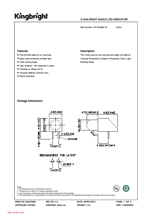
OUT is the output voltage pin. Sources up to 300mA. Bypass with a 3.3µF capacitor to GND.
GND provides the reference for all voltages.
Functional Block Diagram
Output current limit
Thermal overload shutdown protection TO-92, SOT-89 and SOT-23 Package
Applications
Battery Powered Equipment
Palmtops
Portable Cameras and Video Recorders Reference Voltage Sources
temperature TA difference is 100°C. Junction Temperature, TJ ------------------------------------------------------------------------------------------------ +155°C Storage temperature range, TSTG ---------------------------------------------------------------------- -55°C to +150°C Operating junction temperature range ----------------------------------------------------------------- -40°C to +125°C Lead temperature (soldering, 10sec) -------------------------------------------------------------------------------- 260°C
WP1533BQYD;中文规格书,Datasheet资料
分销商库存信息:
KINGBRIGHT WP1533BQ/YD
PACKING & LABEL SPECIFICATIONS
WP1533BQ/YD
SPEC NO: DSAF2053 APPROVED: WYNEC
REV NO: V.4 CHECKED: Allen Liu
DATE: APR/07/2011 DRAWN: J.Yu
PAGE: 4 OF 5 ERP: 1102000844
/
SPEC NO: DSAF2053 APPROVED: WYNEC
REV NO: V.4 CHECKED: Allen Liu
DATE: APR/07/2011 DRAWN: J.Yu
PAGE: 5 OF 5 ERP: 1102000844
/
SPEC NO: DSAF2053 APPROVED: WYNEC
REV NO: V.4 CHECKED: Allen Liu
DATE: APR/07/2011 DRAWN: J.Yu
PAGE: 1 OF 5 ERP: 1102000844
/
Selection Guide
Description
The Yellow source color devices are made with Gallium Arsenide Phosphide on Gallium Phosphide Yellow Light Emitting Diode.
Package Dimensions
Yellow
WP1533BQ/YD
SPEC NO: DSAF2053 APPROVED: WYNEC
REV NO: V.4 CHECKED: Allen Liu
P4SMAJ18CA-T3中文资料

@TA=25°C unless otherwise specified
Symbol PPPM IFSM IPPM PM(AV) Tj, TSTG
Value 400 Minimum 40 See Table 1 1.0 -55 to +150
Unit W A A W °C
Note: 1. Non-repetitive current pulse per Figure 4 and derated above TA = 25°C per Figure 1. 2. Mounted on 5.0mm2 copper pad to each terminal. 3. 8.3ms single half sine-wave duty cycle = 4 pulses per minutes maximum. 4. Lead temperature at 75°C. 5. Peak pulse power waveform is 10/1000µS.
Maximum Ratings and Electrical Characteristics
Characteristic Peak Pulse Power Dissipation at TA = 25°C (Note 1, 2, 5) Figure 3 Peak Forward Surge Current (Note 3) Peak Pulse Current on 10/1000µS Waveform (Note 1) Figure 4 Steady State Power Dissipation (Note 4) Operating and Storage Temperature Range
10
1
10
100
SWF型风机参数

16.5
S3
460
11
1100
53521
ES65S
E3S30
800
980
1100
1450
22
94
544
12
1200
6B35B
6515B
62Q5B
800
11D0
960
22
S5
635
13
1300
84SB6
80SB6
76260
880
990
1120
960
30
&5
736
型号
0
D1
□2
HI
M?
M看
■ 4
1166
122Q
TOD
770
73Q
7K
&3。
6-5Q
14*14
4-4118
15
1212
1275
1330
750
跄。
E70
SSG
S7C
7-00
16-力14
4-3 IS
13
1313
1372
1443
&0G
B70
520
9»0
93C
7S0
16-CC14
4-E1E
型号
气流进部□直役
翼・
<H Vh3
全压cPG
转速
(r/n i n)
960
2SS0
7.5
65
156
7
7M
313BC
之耿力
600
R忖
QS0
14M
11
上如
600
3735C
步进电机选型手册
4
0.8
6.6
FL86BYG80
(串联) 4.5
3
1.6
14
(并联) 4.5
6
0.4
3.5
8.5
4
1.2 11.5
FL86BYG118
(串联) 9.7
3
1.9 22.4
(并联) 9.7
6
0.47 5.6
12
4
1.1 12.8
FL86BYG156
(串联) 13
3
2.23 25.8
(并联) 13
6.1 0.56 6.4
1.4
*以上表中所列仅为代表性产品 外形图:
接线图:
北京飞凌东泰电子技术有限公司
010-69732383
86 方形步进电机系列
技术数据: 步进电机型号
接法
最大静 扭矩 (N·m
±10%)
额定电 流/相
(A)
相阻抗
(ohms ±0%)
相感抗
(mH± 20%)
FL86BYG65
3.5
4
0.7
3.9
4.5
外形图:
接线图:
北京飞凌东泰电子技术有限公司
矩频曲线图:
010-69732383
北京飞凌东泰电子技术有限公司
010-69732383
57 方形步进电机系列
技术数据: 步进电机型号
FL57BYG41
步距角 静力矩 电流 电阻 电感
轴长 机身长 转动惯量 重量
引线数 (NO.)
(°) (N.m) (A) (Ω) (mH)
010-69732383
110 方形步进电机系列
技术数据:
电机型号
- 1、下载文档前请自行甄别文档内容的完整性,平台不提供额外的编辑、内容补充、找答案等附加服务。
- 2、"仅部分预览"的文档,不可在线预览部分如存在完整性等问题,可反馈申请退款(可完整预览的文档不适用该条件!)。
- 3、如文档侵犯您的权益,请联系客服反馈,我们会尽快为您处理(人工客服工作时间:9:00-18:30)。
FS8853300mA LDO Linear RegulatorFortune Semiconductor Co.TEL : +886-2-2809-4742 1/13 TD-0405006 Rev. 1.5FAX: +886-2-2809-4874G e n e r a l D e s c r i p t i o nThe FS8853 is a low-dropout linear regulator that operations in the input voltage range from +2.5V to +9.0V and delivers 300mA output current. The high-accuracy output voltage is preset at an internally trimmed voltage 2.5V or 3.3V. Other output voltages can be mask-optioned from 1.3V to 4.5V with 100mV increment, except FS8853-29Cx which has 2.85V output voltage. The FS8853 consists of a 1.25V bandgap reference, an error amplifier, and a P-channel pass transistor. Other features include short-circuit protection and thermal shutdown protection. The FS8853 devices are available in TO-92, SOT-89 and SOT-23 packages.F e a t u r e sLow dropout voltage 400mV at 300mA (Typ.) Up to ±35mV output voltage accuracy (V IN ≦7V) Preset at 2.5V, 3.3VMask options from 1.3V to 4.5VSmall output capacitor Output current limitThermal overload shutdown protection TO-92, SOT-89 and SOT-23 PackageA p p l i c a t i o n sBattery Powered Equipment PalmtopsPortable Cameras and Video Recorders Reference Voltage SourcesPost Regulator for Switching PowerO r d e r i n g I n f o r m a t i o nFS8853300mA LDO Linear RegulatorFortune Semiconductor Co.TEL : +886-2-2809-4742 2/13 TD-0405006 Rev. 1.5FAX: +886-2-2809-4874P i n C o n f i g u r a t i o n s(BOTTOM VIEW)P a c k a g e M a r k i n g I n f o r m a t i o nFS8853 xxxxxxxx1 23 1 23SOT-23 SOT-89Part No. Pin 1 Pin 2 Pin 3FS8853 -xxxDIN GND OUTFS8853-xxxEGND IN OUTFS8853-xxxF OUT GND INFS8853-xxxWGND OUT IN Pin 1 Pin 2 Pin 3FS8853 -xxxAOUTFS8853-xxxBFS8853-xxxCINFS8853-xxxV INPart No.Pin 1Pin 2Pin 3 FS8853-xxxKIN GND OUTFS8853-xxxLGNDIN OUTFS8853-xxxIOUT GNDIN FS8853-xxxY GND OUTINTO-921 2 3 . . . . .3xxx W . . . .FS8853300mA LDO Linear RegulatorFortune Semiconductor Co.TEL : +886-2-2809-4742 3/13TD-0405006 Rev. 1.5FAX: +886-2-2809-4874P i n D e s c r i p t i o nPart NO. SymbolDescriptionGND Ground pin.IN Regulator input pin.FS8853-xxCA FS8853-xxCB FS8853-xxCC FS8853-xxCV FS8853-xxCD FS8853-xxCE FS8853-xxCF FS8853-xxCW FS8853-xxCK FS8853-xxCL FS8853-xxCI FS8853-xxCYOUT Regulator output pin.IN is the regulator input pin. Supply voltage can range from 2.5V to 9.0V. Bypass with a 1µF capacitor to GND.OUT is the output voltage pin. Sources up to 300mA. Bypass with a 3.3µF capacitor to GND.GND provides the reference for all voltages.F u n c t i o n a l B l o c k D i a g r a mFS8853300mA LDO Linear RegulatorFortune Semiconductor Co.TEL : +886-2-2809-4742 4/13 TD-0405006 Rev. 1.5FAX: +886-2-2809-4874T y p i c a l A p p l i c a t i o n C i r c u i tA b s o l u t e M a x i m u m R a t i n g sInput voltage V INto GND ----------------------------------------------------------------------------------------------------10V Output current limit, I (LIMIT) ------------------------------------------------------------------------------------------------ 0.6A Continuous power dissipation, P D (∆T= T J -T A = 100°C)SOT-23 ---------------------------------------------------------------------------------------------------------------------------------------- 0.31W SOT-89 ---------------------------------------------------------------------------------------------------------------------------------------- 0.55W TO-92 ---------------------------------------------------------------------------------------------------------------------------------------- 0.55W * The power dissipation values are based on the condition that junction temperature T J and ambient temperature T A difference is 100°C.Junction Temperature, T J ------------------------------------------------------------------------------------------------ +155°C Storage temperature range, T STG ---------------------------------------------------------------------- -55°C to +150°C Operating junction temperature range ----------------------------------------------------------------- -40°C to +125°C Lead temperature (soldering, 10sec) -------------------------------------------------------------------------------- 260°C* Stresses beyond those listed under “absolute maximum ratings” may cause permanent damage to the device. These are stress ratings only, and function operation of the device at these or any other conditions beyond those indicated under “recommended operating conditions” is not implied. Exposure to absolute-maximum-rated conditions for extended periods may affect device reliability.FS8853FS8853300mA LDO Linear RegulatorFortune Semiconductor Co.TEL : +886-2-2809-4742 5/13 TD-0405006 Rev. 1.5FAX: +886-2-2809-4874E l e c t r i c a l C h a r a c t e r i s t i c s(T A =25℃, unless otherwise noted.)Symbol ParameterTest ConditionsMin Typ Max UnitV IN Input Voltage2.5 9.0 VV IN =V OUT +0.48V, I OUT =1mA, V IN ≦7V V OUT - 0.035 V OUT V OUT +0.035VV OUT Output VoltageV IN =V OUT +0.48V, I OUT =1mA, 7V <V IN ≦9VV OUT - 0.042 V OUT V OUT +0.042VV IN >V OUT +0.48V, V IN ≦7V-35 +35mV ∆ V OUT Output Voltage AccuracyV IN >V OUT +0.48V, 7V <V IN ≦9V -42 +42mV I MAX Maximum Load Current 300 mA I LIMITCurrent Limit0.6AI SC Short-Circuit Current V OUT =0V, V IN >V OUT +0.48V 140 160 mAI Q Ground Pin Current I LOAD =0mA to 300mA,V IN =V OUT +0.48V 65 120 µAI OUT =1mA 1.1 1.3 mV I OUT =100mA 120 145 mV V DROP Dropout Voltage I OUT =300mA400 480 mV ∆V LINE Line Regulation V OUT +0.48V<V IN <9V, I LOAD =1mA 0.2 0.3 %/V ∆V LOAD Load RegulationI OUT =0mA to 300mA0.01 0.02%/mAe NOutput Noise F=1Hz to 10KHz, C OUT = 3.3µF 70 µV RMSPSRR Ripple RejectionF =10KH z , C OUT =3.3µF 75 dB T SDThermal ShutdownTemperature155 °C T HYSThermal ShutdownHysteresis20 °C SOT-23320 °C/W SOT-89 180 °C/W θJAThermal Resistance TO-92180°C/WFS8853300mA LDO Linear RegulatorFortune Semiconductor Co.TEL : +886-2-2809-4742 6/13 TD-0405006 Rev. 1.5FAX: +886-2-2809-4874T y p i c a l O p e r a t i n g C h a r a c t e r i s t i c s(CIN=1µF , COUT=3.3µF, TA=+25℃, unless otherwise noted.)OUTPUT VOLTAGE vs. INPUT VOLTAGE00.511.522.533.50123456789INPUT VOLTAGE (V)O U T P U T V O L T A G E (V )200mA 100mA300mA*EX :Model FS8853-33CxFS8853300mA LDO Linear RegulatorFortune Semiconductor Co. TEL : +886-2-2809-4742 7/13TD-0405006 Rev. 1.5FAX: +886-2-2809-4874OUTPUT NOISE DC to 1MHz (37uV RMS )OUTPUT NOISE to 1MHz (67uV RMS )LINE TRANSIENT (I OUT =0mA)LINE TRANSIENT (I OUT =10mA)Iload =0mAIload =300mA5.0V 4.0VC IN 1µF C OUT 3.3µF 50mV/divV INV OUT5.0V 4.0VC IN 1µF C OUT 3.3µF 50mV/divV INV OUTFS8853300mA LDO Linear RegulatorFortune Semiconductor Co.TEL : +886-2-2809-4742 8/13TD-0405006 Rev. 1.5FAX: +886-2-2809-4874LINE TRANSIENT (I OUT =100mA)LOAD TRANSIENTLOAD TRANSIENTLINE TRANSIENT (I OUT =200mA)LOAD TRANSIENTLOAD TRANSIENTV INV OUT V INV OUT 5.0V 4.0VC IN 1µF C OUT 3.3µF 50mV/divI OUTV OUT100mA0mAC IN 1µF C OUT 3.3µF 100mV/divI OUTV OUT300mA0mAC IN 1µF C OUT 3.3µF5.0V 4.0VC IN 1µF C OUT 3.3µF 50mV/divI OUTV OUT300mA200mAC IN 1µF C OUT 3.3µF 50mV/div200mA100mAC IN 1µF C OUT 3.3µF 50mV/div100mV/divI OUTV OUTFS8853300mA LDO Linear RegulatorFortune Semiconductor Co.TEL : +886-2-2809-4742 9/13TD-0405006 Rev. 1.5FAX: +886-2-2809-4874D e t a i l D e s c r i p t i o nThe FS8853 is a low-dropout linear regulator. The device provides preset 2.5V and 3.3V output voltages for output current up to 300mA. Other mask options for special output voltages from 1.3V to 4.5V with 100mV increment are also available. As illustrated in function block diagram, it consists of a 1.25V reference, error amplifier, P-channel pass transistor and an internal feedback voltage divider.The 1.25V bandgap reference is connected to the error amplifier, which compares this reference with the feedback voltage and amplifies the voltage difference. If the feedback voltage is lower than the reference voltage, the pass-transistor gate is pulled lower, which allows more current to pass to the output pin and increases the output voltage. If the feedback voltage is too high, the pass-transistor gate is pulled up to decrease the output voltage.The output voltage is feedback through an internal resistive divider connected to OUT pin. Additional blocks include an output current limiter, thermal sensor, and shutdown logic.Internal P-channel Pass TransistorThe FS8853 features a P-channel MOSFET pass transistor. Unlike similar designs using PNP pass transistors, P-channel MOSFETs require no base drive, which reduces ground pin current. PNP-based regulators also waste considerable current in dropout when the pass transistor saturates, and use high base-drive currents under large loads. The FS8853 does not suffer from these problems and consumes only 65µA (Typ.) of ground pin current under heavy loads as well as in dropout conditions.Output Voltage SelectionThe FS8853 output voltage is preset at an internally trimmed voltage 2.5V, 3.3V or can be mask-optioned from 1.3V to 4.5V with 100mV increment. The first two digits of part number suffix identify the output voltage (see Ordering Information ). For example, the FS8853-33CL has a preset 3.3V output voltage.Current LimitThe FS8853 also include a fold back current limiter. It monitors and controls the pass transistor’s gate voltage, estimates the output current, and limits the output current within 0.6A.Thermal Overload ProtectionThermal overload protection limits total power dissipation in the FS8853. When the junction temperature exceeds T J = +155°C , a thermal sensor turns off the pass transistor, allowing the IC to cool down. The thermal sensor turns the pass transistor on again after the junction temperature cools down by 20°C , resulting in a pulsed output during continuous thermal overload conditions.Thermal overload protection is designed to protect the FS8853 in the event of fault conditions. For continuous operation, the maximum operating junction temperature rating of T J = +125°C should not be exceeded.Operating Region and Power DissipationMaximum power dissipation of the FS8853 depends on the thermal resistance of the case and circuit board, the temperature difference between the die junction and ambient air, and the rate of airflow. The power dissipation across the devices is P = I OUT x (V IN -V OUT ). The resulting maximum power dissipation is:()()JA A J CAJCA JMAX T T T T P θθθ−=+−=Where (T J -T A ) is the temperature difference between the FS8853 die junction and the surrounding air, θJC is the thermal resistance of the package chosen, and θCA is the thermal resistance through the printed circuit board, copper traces and other materials to the surrounding air. For better heat-sinking, the copper area should be equally shared between the IN, OUT, and GND pins.If the FS8853 uses a SOT-89 package and thisFS8853300mA LDO Linear RegulatorFortune Semiconductor Co.TEL : +886-2-2809-4742 10/13 TD-0405006 Rev. 1.5FAX: +886-2-2809-4874package is mounted on a double sided printed circuit board with two square inches of copper allocated for “heat spreading”, the resulting θJA is 180 °C/W .Based on a maximum operating junction temperature 125 °C with an ambient of 25°C, the maximum power dissipation will be:()()W T T P CA JCA JMAX 555.018025125=−=+−=θθThermal characteristics were measured using a double sided board with 1” x 2” square inches of copper area connected to the GND pin for “heatspreading”.Input-Output VoltageA regulator’s minimum input-output voltage differential, or dropout voltage, determines the lowest usable supply voltage. In battery-powered systems, this will determine the useful end-of-life battery voltage. The FS8853 uses a P-channel MOSFET pass transistor, its dropout voltage is a function of drain-to-source on-resistance (R DS(ON)) multiplied by the load current.V DROPOUT = V IN -V OUT = R DS(ON) x I OUTFS8853300mA LDO Linear RegulatorFortune Semiconductor Co.TEL : +886-2-2809-474211/13 TD-0405006 Rev. 1.5 FAX: +886-2-2809-4874 P a c k a g e O u t l i n eSOT-23FS8853300mA LDO Linear RegulatorFortune Semiconductor Co.TEL : +886-2-2809-474212/13 TD-0405006 Rev. 1.5 FAX: +886-2-2809-4874SOT-89FS8853300mA LDO Linear RegulatorFortune Semiconductor Co.TEL : +886-2-2809-474213/13 TD-0405006 Rev. 1.5 FAX: +886-2-2809-4874TO-92。