ANSI C57.12.29-1991开关设备和变压器-衬垫安装。。。
美高尔MWA3xx变压器迷你分析仪说明书
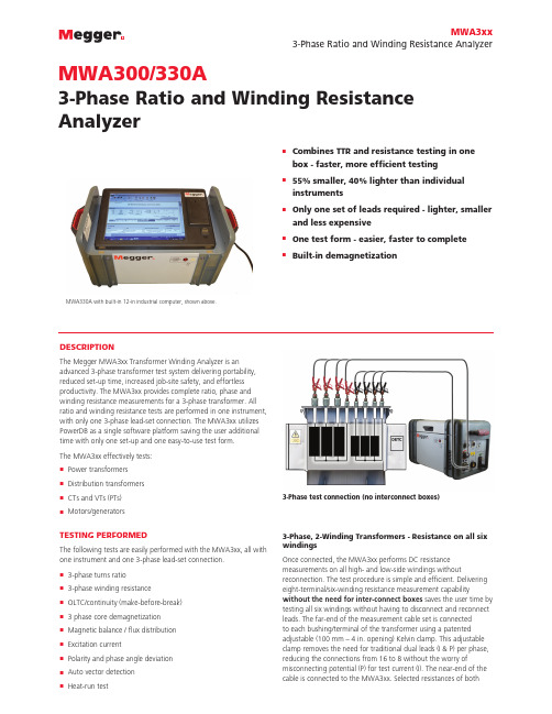
DESCRIPTIONThe Megger MWA3xx Transformer Winding Analyzer is anadvanced 3-phase transformer test system delivering portability, reduced set-up time, increased job-site safety, and effortless productivity. The MWA3xx provides complete ratio, phase and winding resistance measurements for a 3-phase transformer. All ratio and winding resistance tests are performed in one instrument, with only one 3-phase lead-set connection. The MWA3xx utilizes PowerDB as a single software platform saving the user additional time with only one set-up and one easy-to-use test form.The MWA3xx effectively tests:n Power transformers n Distribution transformers nCTs and VTs (PTs)n Motors/generatorsTESTING PERFORMEDThe following tests are easily performed with the MWA3xx, all with one instrument and one 3-phase lead-set connection.n 3-phase turns ratio n 3-phase winding resistancen OLTC/continuity (make-before-break) n 3 phase core demagnetization n Magnetic balance / flux distribution n Excitation currentn Polarity and phase angle deviation n Auto vector detection nHeat-run test3-Phase test connection (no interconnect boxes)3-Phase, 2-Winding Transformers - Resistance on all six windingsOnce connected, the MWA3xx performs DC resistance measurements on all high- and low-side windings withoutreconnection. The test procedure is simple and efficient. Delivering eight-terminal/six-winding resistance measurement capabilitywithout the need for inter-connect boxes saves the user time by testing all six windings without having to disconnect and reconnect leads. The far-end of the measurement cable set is connected to each bushing/terminal of the transformer using a patented adjustable (100 mm – 4 in. opening) Kelvin clamp. This adjustable clamp removes the need for traditional dual leads (I & P) per phase, reducing the connections from 16 to 8 without the worry ofmisconnecting potential (P) for test current (I). The near-end of the cable is connected to the MWA3xx. Selected resistances of bothMWA300/330A3-Phase Ratio and Winding Resistance AnalyzernCombines TTR and resistance testing in one box - faster, more efficient testing n55% smaller, 40% lighter than individual instrumentsnOnly one set of leads required - lighter, smaller and less expensiven One test form - easier, faster to complete n Built-in demagnetizationMWA3xx3-Phase Ratio and Winding Resistance AnalyzerMWA330A with built-in 12-in industrial computer, shown above.HV and LV windings will then be measured. The test sequence can be selected as 6-winding with dual injection simultaneous winding magnetization, up to 4-winding measurement of HV and LV separately, or single-winding test.3-Phase turns ratioComplexity in the measured ratio versus nameplate ratio occurs with most three-phase power transformers due to multipliers, such as √3, which are required to match the measured ratio to the nameplate ratio. Additionally, transformers with zig-zag windings are handled correctly with internal compensation allowing usersto compare nameplate to actual with no corrections needed. The MWA3xx automatically applies the appropriate multiplier which provides a direct comparison to the nameplate ratio.Excitation currentThe excitation current test at low voltage is very useful in locating problems such as defects in magnetic core balance, in magnetic core structure, shifting of windings, failures in the turn-to-turn insulation, or problems in tap changers.Winding balanceWinding balance (also referred to as magnetic balance) is performed to assess the health of the windings, core assembly condition, and flux distribution within the transformer. This test, performed safely and efficiently by the MWA3xx, is a measure of how well balanced (electrically) the transformer is versus nameplate specifications. Check with the factory to ensure your vector group is available with this feature.Phase angle deviationPhase angle deviation is the phase relationship between in-phase vectors of the high-side windings versus the low-side windings. The phase deviation denotes the quality of the core and the winding and should exhibit very low values (0.01 degrees) when the core and windings are functioning properly. Shorted turns, a deteriorated, or damaged core can cause significant changes in the phase deviation values.LTC (OLTC) continuityIn normal LTC operation, continuity between the internal LTC contacts is maintained throughout each complete transition (from one tap position to the next). To check for this continuity, the MWA3xx continually monitors the transition current for each tap position. Any slight discontinuities are detected and reported. Vector recognitionWhen the transformer nameplate data is unavailable, or to confirm compliance to specified nameplate configurations, the MWA3xx provides the capability for automatic vector group detection. PolarityThe MWA3xx quickly and efficiently checks for correct polarity between high and low side windings.Automated heat-run interval testingThe MWA3xx performs automated single or multi-core heat run testing. It uses the standard accepted methods, IEC60076-2-1993 & C57.12.90 2013, for this test, allowing users to perform factory testing automatically. Reports included within software also meets IEEE and IEC standard requirements but does allow manipulation to fit individual customer requirements.Auto core demagnetizationIn order to avoid problems related to core saturation, the MWA3xx comes standard with a core demagnetization function which safely demagnetizes the transformer core after DC testing.PowerDB™ SoftwarePowerDB software provides the unit with a common “user interface” to minimize operator training and provides a seamless interface to the computer application – PowerDB Lite.Two Interface OptionsExternally controlled – MWA300The MWA300 is a “black box” style package that is remote-controlled by PowerDB software running on an external PC (not provided).Built-in 305 mm (12 in.) touch-screen computer –MWA330AThe optional built-in touch-screen computer software provides an industrial, high visibility screen for use on any day – bright or cloudy – and works under the toughest environments. Providing the same test capabilities as the MWA300, the MWA330A comes equipped with an internal computer providing a 305 mm (12 in.) color display with touch-screen interface.FEATURES AND BENEFITSn “One-time” 3-phase connection tests all six windings for faster and safer testing.n No switchbox required, ensuring easier and safer operation.n Unique Kelvin clamps with patented adjustable jaws each open to 100 mm (4-in.) as well as banana plug input for connectionto terminal blocks – no need for special lead sets, and minimal operator error due to lead connections.n Industrial grade 305 mm (12 in.) bright-color touch-screen display available as an option. Usable in direct sunlight, harsh environments – no need for IT intervention, safely stores results and reports.n Checks the contact and timing health of LTC (OLTC) tap changers.n Single-person testing of LTCs is provided standard for use with optional remote tap controller (RTC-1).n PC interface via USB for remote control operation and downloading of test results for ease of use.MWA3xx 3-Phase Ratio and Winding Resistance AnalyzerSPECIFICATIONSInput PowerMWA3xx: 108 to 132 V, (207 to 253 V*), 58 - 62 Hz, 660 VA MWA3XX-47: 207 to 253 V, (108 to 132 V*), 48 - 52 Hz, 660 VA *Input fuse change required - 6.3A fuse for 120 V nominal and 4.0A fuse for 230 V nominal line input.Internal Data StorageMWA330A (built-in computer): up to 100,000 data sets Communication/Control SoftwareMWA3xx: PowerDB LiteMWA330A: Controlled via built-in industiral PC or external customer PC.The MWA330A’s internal computer is designed to control a limited number of Megger instruments including the DELTA4000 as well as the Megger S1 and MIT Series DC insulation testers. EnvironmentalOperating: -10o C to +50o C (14o F to 122o F)Storage: -30o C to +70o C(-22o F to +158o F)Relative Humidity: 0-90% non-condensingCaseRuggedized case (metal/plastic trim) with removable lid andsoft-side pouch with carrying strapSafety/EMC/VibrationConforms to the requirements of:IEC 61010-1:2010ASTMD999.75,IEC 61326-1:2012* (both emissions and immunity)* - see manualDimensions/WeightDimensions290 x 290 x 460 mm (11 x 11 x 18 in.) does not include handles WeightStandard unit: 14.5 kg (32 lbs)Transformer Winding Phase RelationshipANSI C57.12.70-1978CEI/IEC 76-1:1993 and Publication 616:1978AS-2374, Part 4-1982 (Australian Standard)DC Specifications (Winding resistance, LTC/continuity, core demagnetization, heat-run)ResistanceResistance ranges:CurrentRange (A)ResistanceRange (W)Resolution(W)10 A 10 mW to 0.2 W0.00000110 A0.2 W to 2 W0.00011 A100 mW to2 W0.000011 A2W to 20 W0.001100mA 1 m W to 20 W0.0001100mA20 W to 200 W0.0110 mA10 m W to 200 W0.00110 mA200 W to 2000 W0.1Accuracy: ±0.25% Range ±0.25% RdgResolution: Up to 4 digitsExcitation Current SpecificationsRange and Accuracy0 to 500 mA, 3 digit resolution, ±(2% of reading + 1 digit)AC Specifications (Turns Ratio, Winding Balance) Range and Turns Ratio Accuracy:8 V AC:±0.1% (0.8 to 2000)±0.25% (2001 to 4000)±0.35% (4001 to 8000)40 V AC:±0.1% (0.8 to 2000)±0.15% (2001 to 4000)±0.3% (4001 to 10,000)±0.35% (10,001 to 25,000)80 V AC:±0.1% (0.8 to 2000)±0.15% (2001 to 4000)±0.25% (4001 to 10,000)±0.30% (10,001 to 45,000)Phase Specifications (Phase angle deviation, Phase-shift analysis, auto Vector detection)Input voltages: 8, 40, and 80 V ACRange and Accuracy±90 degrees, 2 decimal points for the degree display, or for the centi-radian displayAccuracy: ±3 minutes (from 0.8:1 – 2,000:1)MWA3xx 3-Phase Ratio and Winding Resistance AnalyzerHV Strobe and Leads Cat # 1004-639Length: 18 m (60 ft)Weight: 1.1 kg (2.3 lb)Foam Lined Transit Case Cat # 2005-115Test LeadsNewly designed test leads, shown in image below, are universal and can be used for winding resistance (MTO3XX) or turns ratio (TTR3xx) instruments. Expandable jaws, shown in inset, allow for testing any size transformer.This new design allows tangle and hassle free connection to transformer.Remote Tap ControllerThe RTC-1 is a manually operated remote tap controller designed to provide a more efficient method of controlling (on)load tap changer (LTC) while performing routine tests on power transformers. It removes the need to be physically close to the LTC while testing or to have a second person controlling the LTC while operating the test instrument. A 9 m (30 ft) three-conductor cable is provided to allow proximity to the test instrument while performing testing and advancing tap positions as required throughout the test.OPTIONAL ACCESSORIESAvailable in 9m (30 ft), 18 m (60 ft) and 30 m (100 ft) lengthsONE INTUITIVE, COMPREHENSIVE TEST FORMRATIORESISTANCESALES OFFICE4271 Bronze WayDallas, TX 75237-1019 USA T 1 800 723 2861 (USA only) T +1 214 333 3201F +1 214 331 7399******************MWA3XX_DS_US_V01ISO 9001The word ‘Megger’ is a registered trademark*Please refer to Input Power under Specifications above for details.。
a-nsi标准

a-nsi标准ANSI标准是美国国家标准协会(American National Standards Institute)制定的标准,其制定目的是为了规范和统一美国国内的各种标准,以保证产品的安全、高效和互通性。
ANSI标准已经广泛地应用于全球各行各业,尤其是在航空、电子、医疗、计算机、自动化、建筑和机械等领域,成为了行业里的重要参考标准。
本文将介绍一些与ANSI标准相关的参考内容。
1. ANSI/X9.100-181-2018密码学标准:本标准中规定了基于公钥密码学的数字证书和数字签名的要求以及相关测试程序的标准。
此标准为保障国家安全、金融安全、电子商务以及数字化社会等众多方面提供了核心的技术和标准。
2. ANSI/TIA-568.2-D-2018光纤电缆标准:该标准规定了光纤电缆的安装和测试的方法和要求。
通过该标准的应用可确保光纤电缆在安全运行的同时,不会因使用不当或机器故障而产生故障,保障数据传输的正确性。
3. ANSI/ISA-84.00.01-2004安全标准:该标准规定了工业控制系统能够运作时所必须满足的安全要求。
这些要求包括了硬件基础设施的安全防护、授权用户的实现、紧急事态下的应急处理、以及系统的操作和维护等方面,有助于保证工业控制系统的安全性能。
4. ANSI/NFPA 70国家电气安全标准:此标准是指美国国家消防协会(NFPA)的70号标准,它用来规范电力设备的安全操作和控制,这对于电力系统的平稳稳定运行是至关重要的。
5. ANSI/AWWA C652-92细菌隔离标准:该标准规定了水处理和输送系统的处理分界点和运行标准。
此标准规定了自来水处理系统在分界点位的发挥条件及污染物物质的种类、浓度、含量等指标,从而保证自来水的质量。
6. ANSI/IEEE C57.12.20-2005变压器标准:该标准怎样规定了变压器的安装和使用的所有细节,包括变压器的设计,安装、操作以及维修等方面。
cxb船用变压器标准

cxb船用变压器标准船用变压器是一种在船舶上使用的电气设备,主要用于变换电压以适应船舶系统的电力需求。
为了确保船用变压器的正常性能和安全运行,国际上制定了一系列相关的技术标准和规范。
本文将介绍一些与船用变压器相关的参考内容,这些内容主要涉及国际标准化组织和国际电工委员会等权威组织所制定的标准。
1. IEC 60092-4 "海洋船舶电气装置":这是国际电工委员会制定的标准,规定了海洋船舶上的电气装置的要求,包括船用变压器的设计、制造、安装和运行等方面。
这一标准为船用变压器的设计和应用提供了指导。
2. IEC 60076 "电力变压器":这一系列标准是国际电工委员会制定的,其中包括IEC 60076-1至IEC 60076-12等多个标准,涵盖了电力变压器的各个方面。
其中,IEC 60076-10专门规定了海洋电力变压器的设计和性能要求,该标准在船用变压器设计中有较高的参考价值。
3. IEEE C57.12.50 "接地变压器":这是美国电气和电子工程师协会制定的标准,用于接地变压器(具有特殊绝缘和接地装置的变压器)的设计和应用。
船用变压器的接地设计需要符合该标准的相关要求。
4. ISO 9001 "质量管理体系":这是国际标准化组织制定的用于组织和实施质量管理的标准。
船用变压器制造商可以依据此标准建立和实施质量管理体系,以保证产品的质量和性能。
5. ISO 14001 "环境管理体系":这是国际标准化组织制定的用于组织和实施环境管理的标准。
船用变压器制造商可以依据此标准建立和实施环境管理体系,以满足环保要求并减少与生态系统的不良影响。
此外,还有一些国家和地区制定的标准和规范,如美国国家电气制造商协会(NEMA)制定的标准、欧洲电气厂商联盟(EUREL)制定的标准等,这些标准通常针对特定地区的要求和环境进行规范。
高低压成套开关设备最终检验规范

质量保证体系文件最终检验规范1 范围规范适用于我公司生产的所有高、低压成套设备产品2 引用标准GB/T311.1-1997 高压输变电设备的绝缘配合GB/T1408.1-1999 固体绝缘材料电气强度实验方法工频下的实验GB/T3309-1989 高压开关设备常温下的机械实验GB/T3909-1991 3-35KV交流金属封闭式开关设备GB/T9466-1988 低压成套开关设备基本实验方法GB/T11022-1999 高压开关设备通用技术条件GB/T2681-1981 电工成套装置中的导线颜色3 目的最终产品检验工作是保证产品质量的重要手段,为了保证最终产品质量达到设计要求,满足顾客需求及国家有关法令、法规、特制定本标准。
4 检验原则4.1 有出厂产品都必须进行最终检验且结论合格。
4.2 不具备最终检验依据的产品,检验人员不矛以检验。
4.3 产品最终检验必须逐台逐向检验,有问题及时调整、处理。
4.4 产品经简单调整后能够达到要求的,仍可判为合格品。
5 最终检验项目5.1 一般检查项目。
5.1.1 所装元器件规格型号应正确,并符号相应的技术条件。
5.1.2 主、辅电路接线应正确,并符号相应的技术条件:导线截面和颜色的选择应符合GB/T2681-1981的规定。
5.1.3 产品的铭牌、符号及标志应正确、清晰、齐全,安装位置应正确。
5.1.4 产品的涂覆层应牢固、均匀,无两处以上明显划痕,距产品一米处观查,无明显的色差和反光。
5.1.5 产品外形及安装尺寸应符合图纸、标准及技术文件的要求。
5.1.6 对于产品结构的搭接、零部件和电气元件的保护接地应有专用接地垫圈(或用其他措施),以保证保护电路的连续性。
5.2 对装有分体断路器的开关柜进行机械操作和机械特性试验,参照GB/T3309-1989的规定执行。
5.2.1 分闸时间:5.2.2 合闸时间:5.2.3 合闸同期性:5.2.4 行程、开距、超程:5.2.5 分合闸速度:5.2.6 联锁、保护、信号装置试验:5.2.7 分合闸操作电压、电流试验:5.2.8 脱扣器试验。
煤矿安装工程质量检验评定标准_MT_5010-95上册

UDC中华人民共和国行业标准P MT 5010- 95煤矿安装工程质量检验评定标准standard for quality inspection andassessment of installation engineering of coal mine(上册)1995—04—14发布 1996—01—01实施中华人民共和国煤炭工业部发布目录1 总则 (11)2 质量检验评定的工程划分 (12)3 质量检验评定的等级 (14)4 质量检验评定的程序及组织 (16)5 基本规定 (17)6 多绳摩擦式提升机安装工程 (19)6.1 垫铁,基础螺栓及二次灌浆 (19)6.2 主轴安装 (21)6.3 减速器安装 (23)6.4 导向轮及车槽装置安装 (25)6.5 盘式制动器安装 (26)6.6 液压站安装 (27)6.7 辅助装置安装 (28)6.8 试运转 (29)7 缠绕式提升机及矿用提升绞车安装工程 (32)7.1 垫铁,基础螺栓及二次灌浆 (32)7.2 主轴安装 (32)7.3 滚筒组装 (33)7.4 传动系统安装 (35)7.5 制动系统安装 (36)7.6 液压站安装 (38)7.7 辅助装置安装 (39)7.8 试运转 (39)8 通风机安装工程 (42)8.1 垫铁,基础螺栓及二次灌浆 (42)8.2 机体安装 (42)8.3 反风装置安装 (44)8.4 试运转 (44)9 空气压缩机安装工程 (46)9.1 一般规定 (46)9.2 垫铁,基础螺栓及二次灌浆 (46)9.3 机体安装 (47)9.4 附属设备安装 (49)9.5 室内管道安装 (51)9.6 试运转 (51)10 水泵安装工程 (53)10.1 一般规定 (53)10.2 垫铁、基础螺栓及二次灌浆 (53)10.3 离心泵安装 (54)10.4 深井泵安装 (55)10.5 潜水电泵安装 (56)10.6 室内管道及附件安装 (57)10.7 试运转 (57)11 提升设施安装工程 (59)11.l 提升绳及悬挂装置安装 (59)11.2 平衡绳及悬挂装置安装 (60)11.3 游动天轮安装 (61)11.4 导向装置安装 (62)11.5 罐笼本体结构和阻车器安装 (63)11.6 平衡锤安装 (63)11.7 立井提煤箕斗本体结构安装 (64)11.8 斜井提煤箕斗本体结构安装 (64)11.9 试运转 (65)11.10 立井罐笼制动绳式防坠器提升架安装 (65)11.11 立井罐笼制动绳式防坠器缓冲器安装 (66)11.12 立井罐笼制动绳式防坠器捕绳器安装 (67)11.13 立井罐笼制动绳式防坠器制动绳拉紧装置安装 (68)11.14 立井罐笼木罐道刺入式防坠器安装 (68)11.15 立井罐笼防坠器试验 (69)12 钢结构井架安装工程 (70)12.1 一般规定 (70)12.2 井架制作 (70)12.3 铆接和焊接 (72)12.4 井架组装 (72)12.5 井架安装 (74)12.6 垫铁、基础螺栓、二次灌浆及防腐蚀 (76)12.7 天轮安装 (76)12.8 试运转 (77)13 立井井简装备安装工程 (78)13.1 构件制作及防腐蚀 (78)13.2 罐道梁安装 (80)13.3 树脂锚杆固定托架及梁的安装 (81)13.4 罐道安装 (84)13.5 液压伸缩罐道安装 (86)13.6 钢丝绳罐道安装 (87)13.7 防撞绳安装 (88)13.8 井上下联结部分罐道梁及四角罐道安装 (88)13.9 梁及楔形罐道安装 (89)13.10 井上下防撞梁安装 (90)13.11 管子梁、管座梁安装 (90)13.12 尾绳保护装置安装 (91)13.13 梯子间安装 (92)13.14 电缆支架安装 (94)14 井底箕斗装载设备安装工程 (95)14.1 立井提煤箕斗装载设备安装 (95)14.2 斜井提煤箕斗装载设备安装 (96)14.3 钢梁、基础螺栓安装 (97)14.4 试运转 (97)15 井底撒煤清理设备安装工程 (98)15.1 金属煤仓式清理设备安装 (98)15.2 扒斗式清理设备安装 (99)15.3 试运转 (100)16 井上下操车设备安装工程 (101)16.1 罐座安装 (101)16.2 摇台安装 (102)16.3 井上下平台安装 (104)16.4 井上下安全门安装 (105)16.5 阻车器安装 (106)16.6 链式推车机安装 (107)16.7 绳式推车机安装 (109)16.8 气动式推车机安装 (110)16.9 爬车机安装 (111)17 矿井输送设备安装工程 (114)17.1 胶带输送机安装 (114)17.2 钢丝绳牵引胶带输送机安装 (117)17.3 固定式刮板输送安装 (120)17.4 铸石槽锚链刮板输送机安装 (121)18 矿井其它机械设备安装工程 (124)18.1 无极绳、耙矿、风动、风门、回柱、调度和凿井绞车安装 (124)18.2 翻车机安装 (125)18.3 排矸设备安装 (126)18.4 桥式起重机安装 (127)18.5 卸载站安装 (129)18.6 空气加热室设备安装 (130)18.7 液压注浆泵安装 (131)18.8 泥浆泵安装 (132)18.9 起重葫芦梁,闸门和溜槽安装 (134)19 工业管道安装工程 (135)19.1 一般规定 (135)19.2 管子,管件及闸门的检验 (135)19.3 管道加工 (137)19.4 管道焊接 (140)19.5 管道安装 (142)19.6 管道系统试验及涂漆 (147)20 工业锅炉安装工程 (149)20.1 一般规定 (149)20.2 钢结构组装 (149)20.3 锅筒,集箱安装 (150)20.4 受热面管安装 (152)20.5 受压元件焊接 (154)20.6 省煤器、钢管式空气预热器安装 (156)20.7 水压试验 (157)20.8 仪表、阀门及吹灰器安装 (158)20.9 燃烧设备安装 (161)20.10 炉墙砌筑和绝热层施工 (165)20.11 烘炉、煮炉、严密性试验及试运行 (167)20.12 往复式蒸汽泵安装 (169)20.13 钠离子交换器安装 (171)20.14 除氧器安装 (171)20.15 引风机、鼓风机安装 (173)20.16 除尘设备安装 (174)20.17 出渣系统设备安装 (174)20.18 室内管道、附件安装及防腐蚀与保温 (175)21 井下净水设备安装工程 (177)21.1 预处理间设备安装 (177)21.2 电渗析器安装 (178)21.3 室外管路安装 (180)22 污水处理设备安装工程 (181)22.1 混凝剂投加间设备安装 (181)22.2 污水处理器安装 (183)22.3 曝气器设备安装 (184)22.4 空气压缩机安装 (185)22.5 泵房设备安装 (185)22.6 管道安装 (186)23 给煤设备安装 (187)23.1 一般规定 (187)23.2 往复式给煤机安装 (187)23.3 电磁铁振动给煤机安装 (189)23.4 圆盘给煤机安装 (190)23.5 叶轮给煤机安装 (192)23.6 调速试电机震动给煤机安装 (194)24 破碎设备安装工程 (196)24.1 一般规定 (196)24.2 辊式破碎机安装 (196)24.3 锤式破碎机安装 (198)24.4 颚式破碎机安装 (200)24.5 反击式破碎机安装 (202)24.6 球磨机安装 (205)25 筛分设备安装工程 (209)25.1 一般规定 (209)25.2 矿用座式振动筛安装 (209)25.3 旋转概率筛安装 (212)25.4 弧形筛安装 (214)25.5 电磁震动旋流筛安装 (215)26 主洗设备安装工程 (218)26.1 一般规定 (218)26.2 悬挂式电磁除铁器安装 (218)26.3 辊筒式磁选机安装 (219)26.4 跳汰机安装 (220)26.5 斜轮重介质选煤机安装 (223)26.6 离心式鼓风机安装 (226)26.7 重介旋流器安装 (228)27 脱水设备安装工程 (230)27.1 一般规定 (230)27.2 斗式提升机安装 (230)27.3 卧式振动离心脱水机安装 (232)27.4 立式振动离心脱水机安装 (234)27.5 沉降式过滤离心脱水机安装 (236)28 浮选设备安装工程 (238)28.1 一般规定 (238)28.2 搅拌桶安装 (238)28.3 矿浆准备器安装 (239)28.4 矿浆预处理器安装 (240)28.5 浮选机安装 (241)28.6 药剂站设备安装 (244)28.7 盘式真空过滤机安装 (245)28.8 水环式真空泵(或水环式压缩机)安装 (247)29 压滤设备安装工程 (249)29.1 一般规定 (249)29.2 500㎡及以下箱式压滤机安装 (249)29.3 660~1050㎡箱式压滤机安装 (251)29.4 带式压滤机安装 (253)30 转筒式干燥机安装工程 (257)31 浓缩设备安装工程 (261)31.1 周边传动浓缩机安装 (261)31.2 中心传动浓缩机安装 (263)32 斗轮式堆取料机安装工程 (267)32.1 轨道安装 (267)32.2 行走部件及机架安装 (268)32.3 传动部件及液压气路系统安装 (269)32.4 试运转 (270)33 门式堆取料机安装工程 (271)33.1 轨道安装 (271)33.2 行走部件及机架安装 (271)33.3 活动轮及斗轮机构安装 (272)33.4 开起机构及尾车安装 (273)33.5 试运转 (274)34 计量设备安装工程 (275)34.1 一般规定 (275)34.2 轨道衡安装 (275)34.3 电子皮带称安装 (278)34.4 非接触式计量装置——核称安装 (280)下册35 架空索道安装工程 (287)35.1 钢结构制作 (287)35.2 钢结构安装 (288)35.3 托索轮组(包括压索轮组)安装 (291)35.4 摇摆鞍座安装 (292)35.5 偏斜鞍座安装 (293)35.6 承载索展开和连接 (293)35.7 套筒安装 (295)35.8 承载索锚固 (295)35.9 牵引索安装 (296)35.10 牵引索编接 (297)35.11 驱动轮底座安装 (297)35.12 驱动轮安装 (299)35.13 从动轮安装 (300)35.14 减速器安装 (301)35.15 制动器控制泵站安装 (301)35.16 制动器安装 (302)35.17 驱动机组试运转 (302)35.18 导向轮安装 (303)35.19 迂回轮安装 (304)35.20 滚轮组安装 (305)35.21 吊梁(包括站内支架的支承梁)安装 (306)35.22 吊钩(包括吊架)安装 (306)35.23 轨道(包括扁轨、矩形轨和槽形轨)安装 (307)35.24 道岔安装 (309)35.25 导向板(包括护板和挡板)安装 (309)35.26 挂结器(包括脱开器)安装 (310)35.27 货车安装 (311)35.28 拉紧装置安装 (312)35.29 气动操作设备安装 (315)35.30 气动扇形装车闸门安装 (315)35.31 回转装料机安装 (316)35.32 气动阻发车装置安装 (317)35.33 杠杆计重装置安装 (318)35.34 自动停发车装置安装 (318)35.35 推斗小车安装 (319)35.36 链条推车装置安装 (319)35.37 试运转 (322)36 高压电器安装工程 (325)36.1 3~110kv高压油断路器安装 (325)36.2 3~110kv隔离开关、负荷开关及熔断器安装 (327)36.3 3~110kv阀型避雷器安装 (329)36.4 3~110kv排气式避雷器安装 (332)36.5 电力电容器安装 (333)36.6 水泥电抗器 (335)36.7 高压换向器安装 (337)36.8 真空开关安装 (339)37 电力变压器及互感器安装工程 (341)37.1 变压器安装(包括消弧线圈、油浸电抗器) (341)37.2 3~110kV互感器安装 (344)38 旋转电机安装工程 (347)38.1 电机安装 (347)38.2 特殊电机安装 (350)39 屏、柜及二次回路结线安装工程 (352)39.1 成套高压开关柜安装 (352)39.2 成套低压配电屏安装 (354)39.3 整流装置安装 (356)39.4 二次回路结线 (359)39.5 控制、保护、信号屏台安装 (361)40 低压电器安装工程 (365)40.1 蓄电池组安装 (365)40.2 金属电阻及变阻器安装 (368)40.3 起动器安装 (371)40.4 限位开关安装 (373)40.5 矿灯及充电架安装 (374)41 母线及滑接线安装工程 (377)41.1 母线、支柱绝缘子及套管安装 (377)41.2 地面电机车架线安装 (384)41.3 井下电机车架线安装 (386)41.4 滑接线和软电缆安装 (388)42 送、配电架空线路及电缆安装工程 (391)42.1 一般规定 (391)42.2 杆塔基础 (391)42.3 杆塔组立及拉线 (394)42.4 导线、避雷线架设 (400)42.5 配电线路杆上电器设备安装 (409)42.6 电缆敷设 (412)43 防爆电器安装工程 (423)43.1 高压防爆开关安装 (423)43.2 低压防爆开关安装 (425)43.3 防爆漏继电器安装 (427)43.4 井下照明电器安装 (429)44 接地装置安装工程 (431)45 通信线路及设备安装 (439)45.1 架空通信线路安装 (439)45.2 地面及井下通信设备安装 (442)45.3 光缆敷设 (446)45.4 光缆传输设备安装 (453)46 集控安装工程 (456)46.1 电动转辙器安装 (456)46.2 色灯信号机安装 (457)46.3 传感器及信息传输装置安装 (458)46.4 计算机安装 (459)46.5 模拟盘(屏)安装 (460)46.6 操纵台安装 (461)46.7 信号联络装置安装 (463)附录A 煤矿安装工程分项、分部及单位工程名称 (466)附录B 安装工程质量检验评定表 (477)B.1 分项工程质量检验评定表 (477)B.2 分部工程质量检验评定表 (478)B.3 质量保证资料核查表 (479)B.4 单位工程观感质量评定表 (482)B.5单位工程质量综合评定表 (483)附录C 机械设备通用部分安装质量检验标准 (484)C.1 垫铁 (484)C.2 螺栓连接 (485)C.3 二次灌浆 (488)C.4 铆接 (488)C.5 焊接 (491)C.6 皮带传动、链传动 (496)C.7 减速器安装 (498)C.8 联轴器装配 (498)C.9 齿轮装配 (506)C.10 滑动轴承装配 (512)C.11 滚动轴承装配 (515)C.12 球面轴承 (517)附录D 电气装置试验及技术参数 (521)D.1 电气装置绝缘的交流耐压试验电压标准 (521)D.2 变压器、消弧线圈和油浸电抗器的试验项目和标准 (522)D.3 高压油断路器的检验项目和标准 (526)D.4 交流电动机的试验项目和标准 (527)D.5 直流电动机的试验项目和标准 (531)D.6 悬式绝缘子交流耐压试验标准 (533)D.7 瓷横担绝缘子交流耐压试验标准 (534)D.8 油浸纸绝缘电力电缆长度为250m及以下时泄漏电流参考值 (535)D.9 高压少油断路器技术数据 (536)D.10 高压多油断路器技术数据 (540)D.11 其他几种断路器技术数据 (542)D.12 电磁操动机构技术数据 (543)附录E 电气装置通用部分安装质量检验标准 (547)E.1 二次结线 (547)E.2 硬母线安装 (547)E.3 电气装置接地 (548)附录F 本标准用词说明 (550)总则1.0.1 为统一煤矿安装工程质量标准和检验评定方法,促进企业加强管理,确保工程质量,特制定本标准。
IEEE标准列表
IEEE NESCIR551-2009
IEEE NESCIR550-2008 IEEE NESCIR549-2008 IEEE NESCIR548-2009 IEEE NESCIR547-2008 IEEE NESCIR546-2007 IEEE NESCIR545-2007 IEEE NESCIR544-2007 IEEE N42.48-2008
补充公用事业行业的终端设备数据表的光接口通信协议ieee16762010应用在电力输电和配电系统中的大功率电子器件1mw或更大控制结构用指南ieee1656201038kv以上高架配电系统野生动物防护设施的电气机械和耐用性能测试指南ieee16512010降低鸟类引起的断电指南ieee1609
标准号 IEEE 1581-2011 IEEE C 62.82.1-2010 IEEE 802.3.1-2011
说明.第41节:供给和通信系统.雇主规则410A3一 般要求的规范.总论
第26节:法规261C的B和C级建造的强度要求.牵索 和支索绝缘子
第34节:法规341Blc的地下结构内电缆的安装.检 修孔和拱顶内的电缆.支撑结构
第44节:法规444D供电员工分离励磁设备或线路 用以保护员工的附加法规.员工保护接地
用于保护继电器的电流互感器应用指南.勘误表 1:等式18和等式19的更正
移动电话用可再充电电池 传动装置静态无功补偿器的功能规范指南 国际单位制(SI)使用的ANSI标准:现代米制 国际单位制(SI)使用:现代公制.勘误表
低压(1000 V和更小)交流线路负荷端服务设备用 电涌保护装置(SPDs)的标准试验规范
35kv开关站设计规范

35kv开关站设计规范35kv开关站设计规范篇一:10KV开关站设计规范一个35kV开闭所(开关站)容量一般是XX0kVA(20MVA),出线间隔视情况不同而定。
10kV开闭所(开关站)容量一般在6000~10000kVA(6MVA~10MVA)。
《城市电力规划规范》GB50293-1999第条10kV开关站最大转供容量不宜超过15000kVA 。
根据具体的要求不同,开闭所(开关站)的选择和规模也不同,这个没有固定标准:(1)解决变电站10kV出线开关数量不足,减少相同路径的电缆条数,为中小重要用户提供较为安全可靠的电源,增加电网运行的灵活性,根据具体情况,可建设10kV公用开闭所或配电所。
(2)10kV公用开闭所应配合城市规划和市政工程同时建设,争取与市政设施、公共绿地等合建。
10kV公用开闭所宜建于负荷中心和两座变电站供电范围分界之处,以便于加强电网联络,选址时应考虑设备运输方便,尽量选择在主要道路的附近。
(3)10kV开闭所应有明确的供电范围,出线电缆不宜跨越城市主要干道。
(4)开闭所的接线力求简化和规范,应按无人值班、遥测、遥信、遥控等要求设计,同时应满足防火、通风、防潮、防尘、防毒、防小动物和防噪声等各项要求。
(5)10kV公用开闭所及公用配电所的中压设备宜采用成套配电装置,开关选择要依据负荷性质而确定,一般进出线及1000kVA以上馈线选用真空开关,其它馈线选用负荷开关,有熔断器作保护,母线分段开关需设置备用电源互投装置。
(6)10kV开闭所的规模:每段10kV母线支接配电变压器总容量宜≤5000kVA,进出线回路宜≤8回。
开闭所内部采用单母不分段或分段接线,每座10kV开闭所内宜设置1至2段10kV母线。
(7)为了尽量减少专线,建议大于8000kVA才能申请专线供电,同时应明确每座开闭所最大转供容量,建议≤1XXkVA。
(8)为便于网络拓展和负荷调度,两段10kV母线之间,不宜设置母分开关。
国内外高低压电器及设备标准清单
72. GB 13140.1 -2008
73. GB 13539.1 -2008
74. GB/T 13539.2 -2008
75. GB 13539.3 -2008
动 力 配 电成 套 设备 的 特殊 要 求 低 压 成 套开 关 设备 和 控制 设 备 智能型成套设备通用技术 要求 控制电机基本技术要求 金属封闭母线
87. GB 14048.5 -2008
88. GB 14048.6 -2008
器系统示例 A 至 F
低压熔断器 第 4 部分:半 IEC 60269-4
导体设备保护用熔断体的补 :2006,IDT
充要求
低压熔断器 第 3 部分:非熟 IEC 60269-3-1
练人员使用的熔断器的补充 :1994,IDT
化熔断体示例
高 压 开 关设 备 抗地 震 性能 试
验
剩 余 电 流动 作 保护 装 置安 装 和运行 数字多用表
1992 版
GB/T 13540 -1992
低压开关设备和控制设备 第 1 部分:总则 低压开关设备和控制设备 第 2 部分:断路器 低压开关设备和控制设备 第 3 部分: 开关、隔离器、隔 离开关以及熔断器组合电器 低压开关设备和控制设备 第 4-1 部分:接触器和电动机 起动器 机电式接触器和电 动 机 起 动器 ( 含电 动 机保 护 器) 低压开关设备和控制设备 第 5-1 部分:控制电路电器和 开关元件 机电式控制电路电 器 低压开关设备和控制设备 第 4-2 部分:接触器和电动机 起动器 交流半导体电动机控
27. DL/T 1010.1 -2006
28. DL/T 1010.2 -2006
- 1、下载文档前请自行甄别文档内容的完整性,平台不提供额外的编辑、内容补充、找答案等附加服务。
- 2、"仅部分预览"的文档,不可在线预览部分如存在完整性等问题,可反馈申请退款(可完整预览的文档不适用该条件!)。
- 3、如文档侵犯您的权益,请联系客服反馈,我们会尽快为您处理(人工客服工作时间:9:00-18:30)。
Annex B (informative)Bibliography ............................ห้องสมุดไป่ตู้...............................................................................................10
2. Normative references ..........................................................................................................................................2
This standard covers conformance tests and requirements for the integrity of above grade pad-mounted enclosures intended for installation in coastal environments. Other performance requirements may be needed to provide long field life in other contaminated environments. These enclosures contain apparatus energized in excess of 600 volts that may be exposed to the public including, but not limited to, the following types of equipments enclosures:
1.2 Purpose
The purpose of this standard is to describe the requirements for a comprehensive integrity system for pad-mounted enclosures providing long field life with minimum maintenance and positively safety features.
4. Enclosure security ...............................................................................................................................................3
3. Definitions...........................................................................................................................................................2
1.1 Scope.......................................................................................................................................................... 1 1.2 Purpose....................................................................................................................................................... 1
Pad-mounted capacitors or inductors; Pad-mounted distribution transformers; Pad-mounted junction enclosures; Pad-mounted metering equipment; Pad-mounted switchgear. This standard does not cover installations that are under the exclusive control of electric utilities and that are located in such a manner that access to the equipment is controlled exclusively by the utility.
CLAUSE
PAGE
1. Scope and purpose ..............................................................................................................................................1
5. Enclosure corrosion resistance and coating system requirements ......................................................................3
5.1 Enclosure design requirements – Objective............................................................................................... 3 5.2 Substrata requirements ............................................................................................................................... 4 5.3 Coating system requirements ..................................................................................................................... 4 5.4 Coating system test specimens................................................................................................................... 6 5.5 Coating system performance requirements................................................................................................ 6
ANSI C57.12.28-1988, Switchgear and transformers – Pad-mounted equipment – Enclosure integrity ASTM B117-85 E1, Standard method of salt spray (fog) testing1) ASTM D523-85 E1, Standard test method for specular gloss1) ASTM D1654-79A, Method for evaluation of painted or coated specimens subjected to corrosive environments1) ASTM D2794-84, Standard test method for resistance of organic coatings to the effects of rapid deformation (impact)1 ASTM D3359-83, Standard methods for measuring adhesion by tape test1) ASTM D4060-84, Standard test method for abrasion resistance of organic coatings by the Taber abraser1) ASTM D4585-86A, Standard practice for testing water resistance of coatings using controlled corrosion1)
6. Labels ..................................................................................................................................................................8
ANSI C57.12.29-1991
American National Standard for Switchgear and Transformers— Pad-Mounted Equipment— Enclosure Integrity for Coastal Environments
Approved 8/9/91 American National Standards Institute, Inc.
Annex A (informative) Procedure for comparative weight loss on welded and non-welded unpainted stainless steel ..........................................................................................................9