Kistler测力仪 9253B
Kistler 4504B扭矩测量法兰说明书

Page 1/7Torque Measuring FlangeShort Profile, Robust, Bearingless, High Accuracy, 50 ... 5 000 N·m4504B _000-805e -10.13TorqueThis information corresponds to the current state of knowledge. Kistler reserves the right to make technical changes. Liability for consequential damage resulting ©2009 ... 2013, Kistler Group, Eulachstrasse 22, 8408 Winterthur, Switzerland Type 4504B...Type 4504B... torque measuring flanges operate on the strain gage principle. The integral, digital measurement precondi-tioning system produces analog or digital output signals, which are transmitted without contact. The rotor runs in the stator ring without mechanical bearings and is therefore free from wear.• Accuracy class 0,1 for frequency and voltage output avail-able• Dust and moisture proofed magnetic speed/angle acquisi-tion system with high resolution • I dentification, parameterization, measuring and zero point taring via RS-232C is standard • Very short axial dimensions• Compact flange-to-flange solution • Digital non-contact signal transmission • Maintanance-free, bearingless• Electrical control signal to test sensor functions • Active temperature compensation • Calibrated RS-232C outputDescriptionType 4504B... torque measuring flange was designed to be a very short flange-to-flange solution and its rotor can be in-stalled from one side (normally the test specimen side), straight to the flange of the loading machine. This allows easy, cost-ef-fective assembly into a power train. Speed acquisition system is fully integrated within sensor construction.The rotor is usually attached to the flange of the load machine. The stator is aligned at the mounted rotor and held by the stator support.Data transmission is not affected by surrounding metal parts, so that it is not necessary to regard minimum distances to other machine parts.Geometry, dimensions, materials, measuring system and signal transmission are designed especially for raw and complex ap-plications in engine test rigs.Options• Analog output or frequency output• Speed measurement up to 60 pulses/rev.• Rotational angle measurement, resolution up to 3 600 puls-es/rev. (depends on size)ApplicationThe extremely narrow profile of the torque measuring flange Type 4504B... makes it very suitable for many test rig applica-tions: Test bed for engines, dynamometer, wheel load simula-tion, gear boxes, pumps, electric motors and many others.Page 2/74504B _000-805e -10.13This information corresponds to the current state of knowledge. Kistler reserves the right to make technical changes. Liability for consequential damage resulting ©2009 ... 2013, Kistler Group, Eulachstrasse 22, 8408 Winterthur, Switzerland Tel.+41522241111,Fax+41522241414,****************, General Electrical Specifications Output signalVDC ±0 ... 10 at M nom (rated value) VDC 10**Load resistancekΩ >10Limit frequency −3 dB kHz 2100 % control input VDC "On" 3,5 (30)"Off" 0 ... 2Control signal %FSO 100 ±0,1Supply voltage VDC 11 (30)Power consumptionW <5Electrical Measuring Data Accuracy class 0,1Linearity errorincluding hysteresis %FSO <±0,05Temp. influence on the zero point %FSO/°C <±0,005Temp. influence on the nominal value %FSO/°C <±0,01Zero point stability (for 24 h) %FSO 0,03Reference temperature °C22 ±2Operating temperature range °C 10 ... 60 (Rated temperature range)Service temperature range °C 0 ... 70Storage temperature range°C−25 (80)Speed and Angle Measurement Speed measurement option N1 Pulses/revolution1x60 Max. distance from rotor to probe mm 2,5Angle measurement option N2Pulses/revolution (Track A and B) 2x720 (2x600*)90° displaced, TTLMax. distance from rotor to probe mm1,0(adjustable)Angle measurement option N3Pulses/revolution (Track A and B) 2x1 02490° displaced, TTLMax. distance from rotor to probe mm 1,0(adjustable)Technical DataMechanical Basic Data Type 4504B...050...100...200...500...1k0...2k0...3k0...5k0...Rated torque M nom N·m 50100200500 1 000 2 000 3 000 5 000Measuring range N·m ±50±100±200±500±1 000±2 000±3 000±5 000Limiting torque M op N·m 100200400 1 000 2 000 4 000 6 00010 000Rupture torque M rupt N·m >200>400>800>2 000>4 000>8 000>12 000>20 000Alternating torque M dyn N·m 50100200500 1 000 2 000 3 000 5 000Nominal speed n nom 1/min 15 00015 00015 00012 00012 00010 00010 0008 000Torsional rigidityC T kN·m/rad 66238375945 1 462 3 220 5 08911 442Rotation angle at M nom ϕ°0,0380,0210,0320,0410,0530,0590,0560,052Max. bending torque M B N·m 4080130230600700 1 400 3 000Max. axial force F A kN 246810152530Rotor weight m rotor kg 0,90,951,7334,56,210,5Stator weightm stator kg1,41,41,61,91,92,52,52,5Moment of inertia (rotor)j rotorkg·m 2·10−31,51,6411,611,125,227,891,6Partial mass of the rotor (measurement side)also for option N1, N2 m rotor-M kg0,330,360,751,21,1522,84,5Partial moment of inertiaof the rotor (measurement side also for option N1, N2) j N1-M kg·m 2·10−30,40,461,443,810,114,236,6Balancing class Q6,3Housing material Hard anodized aluminumProtection classIP54**Further options available*With nominal torque 50 N·m and 100 N·m (Size 1)Page 3/74504B _000-805e -10.13This information corresponds to the current state of knowledge. Kistler reserves the right to make technical changes. Liability for consequential damage resulting ©2009 ... 2013, Kistler Group, Eulachstrasse 22, 8408 Winterthur, Switzerland Tel.+41522241111,Fax+41522241414,****************, DimensionsDimensions in mmPage 4/74504B _000-805e -10.13This information corresponds to the current state of knowledge. Kistler reserves the right to make technical changes. Liability for consequential damage resulting ©2009 ... 2013, Kistler Group, Eulachstrasse 22, 8408 Winterthur, Switzerland Tel.+41522241111,Fax+41522241414,****************,Electrical ConnectionsPin Allocation of the 12-Pin Built-in M16 Standard Connector APin Allocation of the 7-Pin Built-in Standard Connector BFig. 1: Pin allocation of the built-in connector A and B (Voltage B1)Fig. 2: Pin allocation of the built-in connector A and B (Frequency B2/ B3/B4) ** Can be switched over in the torque measuring flangePage 5/74504B _000-805e -10.13This information corresponds to the current state of knowledge. Kistler reserves the right to make technical changes. Liability for consequential damage resulting ©2009 ... 2013, Kistler Group, Eulachstrasse 22, 8408 Winterthur, Switzerland Tel.+41522241111,Fax+41522241414,****************, Electrical ConnectionsFig. 3: Pin allocation of the built-in connector C and D (Voltage B1)** Can be switched over in the torque measuring flangeFurther konfigurations of output are adjustable (see instruction manual)Pin Allocation of the 7-Pin Built-in M16 Connector CPin Allocation of the 8-Pin Built-in M16 Connector DFig. 4: Pin allocation of the built-in connector C and D (Frequency B2/ B3/B4)** Can be switched over in the torque measuring flange1)Pin 1 and Pin 7: at N2 and N3 can be switched over in the flangePage 6/74504B _000-805e -10.13This information corresponds to the current state of knowledge. Kistler reserves the right to make technical changes. Liability for consequential damage resulting ©2009 ... 2013, Kistler Group, Eulachstrasse 22, 8408 Winterthur, Switzerland Tel.+41522241111,Fax+41522241414,****************, MountingRotor8x Hex socket head screw (ISO 4762)8x Fastening boltThreaded Joint of Rotor, Fastening Bolts Important: mounting depth has to be strictly observed!Application ExamplesEngine Test Rig:Calibration Facility:EngineDrive ShaftTorque Measuring Flange Type 4504B...Loading Machine (locked)Bearing SupportNominal torque M nom N·m50100200500 1 000 2 000 3 000 5 000ThreadM6M6M8M12M12M14M14M18Quality class10.910.910.910.910.910.910.910.9Min.mounting depth mm 6681313162121Max. mounting depth mm1515162222263135Fastening torque M fast N·m141434100115185185400Balancing classQ 6,3Counterflange flatness mm 0,01Counterflange concentric.mm 0,02Max. delay rotor to stator Axial mm ±1Radialmm±1,5Page 7/74504B _000-805e -10.13This information corresponds to the current state of knowledge. Kistler reserves the right to make technical changes. Liability for consequential damage resulting ©2009 ... 2013, Kistler Group, Eulachstrasse 22, 8408 Winterthur, Switzerland Tel.+41522241111,Fax+41522241414,****************, Included Accessories • NoneOptional Accessories Type/Art. No.• Connection cable, length 5 m KSM007203• Connection cable, length 5 m, 12 pin – open ends KSM124970-5• Connection cable, length 5 m, 7 pin – open ends KSM219710-5• Connection cable, length 2,5 m, 12 pin – CoMo Torque KSM186420-2,5• Female connector 7 pin (plug C) KSM000517• Female connector 8 pin (plug D) KSM013136• ControlMonitor CoMo Torque 4700B... • Evaluation instrument for torque sensors • Adapter flange 2300A...• Torsion proof multi-disk coupling 2300A...• SensorTool 4706AOur torque calibration service lab DKD-K-37701 offers trace-able recalibration of any brands.For further information of cable and connector see data sheet 000-615.Order Example: Type 4504B1k0B1N1Torque sensor : Rated torque 1 000 N∙m 1k0, Analog output ±10 V, Speed measurement with 60 pulses/rev.Ordering Key。
分析仪KISTLER

优点: 便携, 同时适用台架和车载燃烧分析 基于 Windows 系统,易于升级 可同时作为高性能通用数据采集系统 性能价格比优 产品包括:KISTLER 压力传感器、KISTLER 力传感器、KISTLER 加速度计、 KISTLER 加速度传感器、KISTLER 电子压头、KISTLER 分析软件
9313,9323,9333,9343,9363 9931A1,9931A4,9039/9049/9069,9345A,9275,9277A5,9143B,9251A/9252A,9067C/ 9068C,9602A,9317B,9327A,9420A,9232A 9017B/9018B,9047C/9048C,9067/9068,9067C/9068C,9077B/9078B,,9347C,9367C,9 377B,9366BB,9203,9205,9207,9215,9217A 分析仪 KISTLER 两种典型应用: 发动机试验台 发动机试验台可识别发动机的所有工作点(功率,转 速,爆震等),并将这些数据储在 ECU 中作为参考,以正确进行车辆的闭环控制。
分析仪 KISTLER
编辑者:广州南创 谭工
分析仪 KISTLER、KISTLER 力传感器、KISTLER 加速度计、KISTLER 加速度 传感器、KISTLER 电子压头、KISTLER 分析软件。特价代理瑞士奇石乐 KISTLER 压力传感器、KISTLER 力传感器、KISTLER 加速度计、KISTLER 加速度传感器、 KISTLER 电子压头、KISTLER 分析软件等等。瑞士 KISTLER(奇石乐)作为世界 领先的测量仪器制造商, 提供 KISTLER 压电式压力传感器、KISTLER 压阻式压 力传感器, KISTLER 力传感器,KISTLER 测力仪, KISTLER 加速度计及相应的电 子和分析软件。KISTLER 的产品在30多个国家设立了国外办事处及售后服务中 心,并在中国设立了广州南创传感器事业部,为 KISTLER 提供最佳的服务与解 决方案。奇石乐为航天、航空、汽车和军工等许多领域的科研和生产提供广泛的 解决方案。以下为典型的应用领域:内燃机燃烧分析试验;注塑过程的质量控制; 内弹道压力测量;切削力的测量和分析;零次品生产和产品测试的过程监测;运 动和医学生物力学测量;振动和模态分析。 分析仪 KISTLER 图片:
KH2便携式测力仪表使用说明书

KH2便携式测力仪表使用说明书目录1注意事项 (1)2功能与特点 (1)3型号与技术规格 (2)3.1型号规格 (2)3.2技术规格 (2)3.3产品外形及尺寸 (3)4使用 (3)4.1电源 (3)4.2传感器接口 (3)4.3按键 (4)4.4标定(校准) (4)4.5系统设置菜单 (6)4.5.1日期时间设置 (6)4.5.2显示亮度 (7)4.5.3 定时关机 (7)4.5.4 上下限设置 (7)4.6删除记录 (7)4.7设备信息 (7)4.8查看记录 (7)4.9工作界面 (8)5其它注意事项 (8)1注意事项感谢您购买KH2便携式测力计。
为了确保产品正确使用,请在使用之前仔细阅读本手册。
收到产品后请根据随机装箱清单检查包装内物品是否齐全或损坏。
请核对您收到的产品型号是否与订单一致。
产品型号在产品上方的铭牌标签上。
如发现新开箱产品有部件遗漏,损坏,或型号规格不一致情形,请准备好证据(如订单号,收货日期,产品序列号)并及时与我公司最近的办事处,授权机构,或售后服务部联系。
电源:本仪表内置3.6V/2300mAh耐低温锂电池。
请用标配的电源适配器进行充电。
请在常温环境充电。
报废的电池请妥善处理,不能随便丢弃。
2功能与特点KH2系列便携式测力计采用先进的Cortex-M3单片机平台,精密ADC转换器,通过外接的应变式传感器,测量实时力值。
仪表内置耐低温锂电池,自发光OLED显示器,可以实现上下限判断,20笔存储信息。
KH2主要功能特点:⏹便携式设计,传感器接口采用军标航空插头⏹具有实时时钟⏹内置耐低温锂电池⏹可保存20条记录⏹汉化界面,导航式菜单⏹上下限声光报警3型号与技术规格3.1 型号规格3.2 技术规格产品尺寸(WxHxD)103mm×220mm×40mm。
产品自重约0.4kg传感器接口驱动最多2只350Ω传感器,或等效阻抗大于175Ω的传感器负载。
输入信号范围:-6mV ~ +6mV。
巴柯尔硬度计

巴氏硬度计简介:巴柯尔硬度计又称为巴克尔硬度计、巴式硬度计,934-1硬度计,934-1巴氏硬度计,巴柯尔硬度计价格,巴柯尔硬度计厂家,巴柯尔玻璃钢硬度计,铝合金硬度计,巴氏硬度测量仪是一种压痕硬度计,它以特定压头在标准弹簧力的作用下压入试样,以压痕的深度确定试样的硬度。
巴氏硬度计有100个刻度,每个刻度代表压入0.0076mm的深度。
可测量的材料:铝、铝合金、软金属、塑料、光纤、消防梯、复合材料、橡胶或皮革。
玻璃钢等。
用途巴氏硬度计主要用于测试铝及铝合金。
测试铝型材、板材、管材、棒材及铝合金铸件、锻件、机械加工零件,测试超厚铝合金材料及组装后的铝合金制品(例如铝合金门窗、幕墙、消防梯等)。
相关标准:ASTM B648《巴柯尔硬度计测量铝合金硬度的试验方法》。
巴氏硬度计的另一主要应用是用于测试玻璃钢(玻璃纤维增强塑料)和硬塑料。
大部分玻璃钢制品的产品标准中都要求测试巴氏硬度。
相关标准:GB/T3854—2005《增强塑料巴柯尔硬度试验方法》、ASTM D2583—07《巴氏硬度计测量硬塑料压痕硬度的试验方法》。
巴氏硬度计的改进型935—1、936—1可用于测试很软的金属、软塑料、皮革、橡胶、木材等。
目录一、概述 (1)二、原理与结构 (2)三、技术参数 (3)四、使用方法 (3)五、仪器校正 (4)六、压针 (5)七、硬度块 (7)八、测量次数 (7)九、型号选择 (8)十、配置 (8)十一、硬度换算表 (9)一、概述巴氏硬度计(巴柯尔硬度计)是一种压痕式硬度计,最早产自美国。
巴氏硬度计有三种型号,其中OU2800-1型巴氏硬度计是代表型产品,应用量最大,一般提到巴氏硬度计主要是指OU2800-1型。
巴氏硬度计主要应用于以下两个领域:其一是铝加工行业,用于测试纯铝、较软的铝合金、较厚的铝合金、铝板带、铝型材、铝棒、铝铸件、铝锻件及组装好的铝合金制品(铝合金门窗、幕墙等)。
相关标准是美国标准ASTM B68-00《使用巴氏硬度计测量铝合金硬度的试验方法》。
kistler 9301c-9371c 力传感器 操作手册说明书

Page 1/6ForcePiezoelectric Load Cellsfor measuring dynamic and quasistatic tensile and compression forces9301C _003-556e -09.21© 2021 Kistler Group, Eulachstrasse 22, 8408 Winterthur, Switzerland. Kistler Group pro-This information corresponds to the current state of knowledge. Kistler reserves the right to make technical changes. Liability for consequential damage resulting from Type 9301C ... 9371CPiezoelectric load cells, also known as force transducers or force links, measure dynamic or quasistatic forces, both ten-sile and compression. These load cells contain a piezoelectric ring force transducer of the 90x1C family: preloaded and cali-brated, thus ready to use immediately. • Calibrated and ready to use • Simple installation• Centering seats for exact installation • Ground-isolated• Accessories for optimum force introductionDescriptionThe 93x1C load cell family is the easiest way to measure forces piezoelectrically without the need for sophisticated installation and calibration. The force transducers are factory calibrated and preloaded to measure both tension and compression forc-es. This means, that the sensor is ready to measure within minutes and provides accurate data from dynamic or quasi-static processes. In addition, the sensor has been installed in an electrically isolated manner, so that ground loops are largely eliminated.ApplicationQuasistatic measurements are possible without any problems, but the 93x1C is mainly used where dynamic processes have to be recorded exactly. Due to the extremely high stiffness of the piezoelectric load cell, the elastic behavior of the measured object is practically unchanged.The force link comes calibrated in 3 different ranges and is im-mediately ready for use.Examples of Use Automobile industry• Safety technology, monitoring of collision forces • Mechanical shocks in chassis • Forces on balancing machines Material testing• Impact testing, alternate strength testing Machine tools• Monitoring on presses, punching, embossing and welding machines• Force measurements on longitudinal guidewaysMounting and Force IntroductionThe mounting of these force transducers is quite simple, but nevertheless it should be done carefully and correctly:• The contact surfaces must be flat, clean, parallel and as rigid as possible.• The fixing screws must not touch the threaded base.• The mounting screw must be tightened so that no gap is created at maximum tensile force.The force application should be as concentric as possible with the sensor axis. Eccentric force introduction, bending moments, torques and shear forces are only permissible up to a certain degree. For further details, please refer to the user manual.General machine building• Monitoring of supporting forces (force oscillations) on machinery mounted on damping elements.• Clamping processes, e.g. force sensor combined with hydraulic cylinder• Joining technique (insertion, press fit of components)Quality control• Force measurements on switches• Monitoring of automatic assembly machinesPage 2/6© 2021 Kistler Group, Eulachstrasse 22, 8408 Winterthur, SwitzerlandTel.+41522241111,****************,. Kistler Group pro-This information corresponds to the current state of knowledge. Kistler reserves theright to make technical changes. Liability for consequential damage resulting from 9301C _003-556e -09.21Technical DataType 9301C 9311C9321C 9331C 9341C 9351C 9361C 9371C Nominal force kN ±3 ±6 ±14 ±24 ±36 ±48 ±80 ±160Calibrated range 1 kN 0 ... 3 0 ... 6 0 ... 14 0 ... 24 0 ... 36 0 ... 48 0 ... 80 0 ... 160Calibrated range 2 kN 0 ... 0.03 0 ... 0.06 0 ... 0.14 0 ... 0.24 0 ... 0.36 0 ... 0.48 0 ... 0.8 0 ... 1.6Calibrated range 3 kN 0 ... -3 0 ... -6 0 ... -14 0 ... -24 0 ... -36 0 ... -48 0 ... -80 0 ... -160Maximum force kN ±3.3 ±6.6 ±15.4 ±26.4 ±39.6 ±52.8 ±88 ±176Sensitivity pC/N -3.1 ±0.3 -3.4 ±0.3 -3.7 ±0.3 -3.9 ±0.3 -4.0 ±0.3 -3.9 ±0.3 Linearity incl. hysteresis %FSO ±0.5 ±0.7Natural frequency (free-free) f 0fz calc. kHz 58.5 50.6 41.2 36.9 29.7 27.9 23.8 19.9Axial stiffness (calc.) N/µm 245 398 724 1 150 1 510 1 756 2 597 4 794Lateral stiffness (calc.) 1)N/µm 6 14 27 48 74 86 136 316Shear stiffness (calc.) N/µm 22 47 76 130 210229 349 733Torsional stiffness (calc.) Nm/° 15 53 254 633 1 387 2 269 5 540 21 231Bending stiffness (calc.) Nm/° 22 78 355 865 1 926 3 105 7 619 28 411Maximum bending moment Fz=0 calc. N·m 4.2 12 49 104 195 312 640 1 955Temperature sensitivity Sensitivity change(-40°C ... 120°C, Tref = 25°C) % ±2.5 ±1.5 Operating temperature range °C -40 (120)Insulation resistance @23°C Ω ≥1013Ground insulation resistance Ω ≥108Sensor capacitance pF 13.5±1 17±2 33±4 52±5 70±6 93±7 149±10 303±20Connector type KIAG 10-32 neg.Degree of protection EN60529 IP See table, page 5Weight g 14 28 90 170 330 480 1 020 2 5001)Resistance of the sensor to shear and bending deformation. (Theoretical) assumption: The sensor is fixed at the bottom, the shear force acts at the top, so that the lever length is equal to the total sensor height.Type M D1 D2 D3 S W H H1 H2 s t 9301C M5 8,5 11 10,3 9 25 2 5 12,75 7,259311C M6 12,5 15 14,5 13 30 3 5,5 14,85 7,259321C M10 18 23 22,5 19 45 5 10 18,6 7,259331C M12 23 29 28,5 24 52 5 11 21,65 7,259341C M16 31 35 34,5 32 62 6 14,5 24,65 7,259351C M20 35 41 40,5 36 72 7 18 27,65 7,259361C M24 45 53 52,5 46 88 9 22 33,65 7,259371C M30 64 76 77,2 65 108 10 28 45 6,75Dimensions of Types 9301C ... 9371CPage 3/6© 2021 Kistler Group, Eulachstrasse 22, 8408 Winterthur, SwitzerlandTel.+41522241111,****************,. Kistler Group pro-This information corresponds to the current state of knowledge. Kistler reserves the right to make technical changes. Liability for consequential damage resulting from 9301C _003-556e -09.21Calibration and measuring rangesThe expected error deviations of a sensor are directly depen-dent on the size of the measuring range and the choice of the operating point. The smaller the measuring range, the better the linearity and hysteresis.The piezoelectric force transducers 93x1C are preloaded with 60% of the nominal force of the 90x1C sensor built into them. This enables the measurement of equally large positive and negative forces.The lowest 20% of the nominal force range is not taken into account, since the susceptibility to moments, shear forces and non-linearities is highest there.The load cells 93x1C are calibrated in three different ranges: +100%, -100%, +1%.A detailed operating manual with further explanations of I nstallation, dimensioning and cabling can be found in the download area of our website .Mounting Examples, Different Types of Force IntroductionExample AExample BExample CForce introduction of compression forces.Loading from tensile and compression forces via an extension piece. The preloading force on the sleeve must not be less than a mini-mum value under the effect of tensile forces.Force introduction of tensile and compres-sion forces directly onto the threaded con-nection. I n this case, a lock nut should al-ways be used.Example DMounting example of a force link in a hy-draulic clamping device. Monitoring of ten-sile and compression forces.Example CPage 4/6© 2021 Kistler Group, Eulachstrasse 22, 8408 Winterthur, SwitzerlandTel.+41522241111,****************,. Kistler Group pro-This information corresponds to the current state of knowledge. Kistler reserves the right to make technical changes. Liability for consequential damage resulting from 9301C _003-556e -09.21Distributing cap Type 9500A...The force distributing cap can be screwed in with a cylindrical tool.Flange Type 9501A...A socket head cap screw is supplied with the flange.Fig. 1Force link with flange and pressure distributing cap. Insert for compression force loading.Fig. 2Force link with flanges fitted on both sides. Insert for compression force loading.Type Distribut. cap D2 L H4 R d 9301C 9500A0 8,5 8 4 R10 2,29311C 9500A1 12,5 10 6 R15 3,29321C 9500A2 18 17 9 R25 4,39331C 9500A3 23 21 12 R35 4,39341C 9500A4 31 28 15 R45 6,49351C 9500A5 35 33 18 R50 6,49361C 9500A6 45 41 22 R65 8,49371C 9500A7 64 57 32 R90 8,4Type Flange D3 H3 d1 d2 d3 C H1 H2 (Fig. 1) (Fig. 2)9301C 9501A0 25 9 8,5 18 3,2 8 37 419311C 9501A1 34 11 12,5 24 4,3 9 45 489321C 9501A2 44 18 18 33 5,3 16 70 779331C 9501A3 56 22 23 42 6,4 20 84 929341C 9501A4 70 29 31 52 8,4 27 104 1169351C 9501A5 84 37 35 62 10,5 35 125 1429361C 9501A6 102 44 45 77 13 42 152 1729371C 9501A7 136 53 64 106 17 51 191 210Force distribution capIf the Force Link is not firmly installed in a structure on both sides, there is always the risk, that the force might be intro-duced eccentrically. The force distribution cap helps to signifi-cantly increase the precision and repeatability of the measure-ment with an exactly defined point of force application.FlangeI f installation with the central bolt is not possible directly, the flange 9501Ax is installed. The precision part can be used for both compressive and tensile forces, as shown examples A...D on page 3.Page 5/6© 2021 Kistler Group, Eulachstrasse 22, 8408 Winterthur, SwitzerlandTel.+41522241111,****************,. Kistler Group pro-This information corresponds to the current state of knowledge. Kistler reserves the right to make technical changes. Liability for consequential damage resulting from 9301C _003-556e -09.21Measuring chainMeasureConnectAmplifyConnecting cableAll sensors of 9301C...9371C feature a KI AG 10-32 neg. connection and are compatible accordingly with all K AG 10-32 pos. cable connectors. Only high-insulation coaxial cables with low capacitance that produce only a very small amount of static electricity may be used as connecting cables for piezoelectric sensors. Kistler uses cables made of high-qua-lity PFA or oil-proof FPM here.On the sensor side, the IP protection class acc. to EN60529 is generally dependent on the used connector. For IP65, the standard 10-32 KI AG cable connector with knurled nut is used; for increased requirements in harsh environments, the industrial-suited 10-32 KIAG pos. int. version is used which, if necessary, can be tightly welded with the sensor case and IP68 achieved.Fig. 3: Measuring chainCompatibilities of cables and charge amplifiersPage 6/6© 2021 Kistler Group, Eulachstrasse 22, 8408 Winterthur, SwitzerlandTel.+41522241111,****************,. Kistler Group pro-This information corresponds to the current state of knowledge. Kistler reserves the right to make technical changes. Liability for consequential damage resulting from 9301C _003-556e -09.21Charge amplifiersVarious criteria are decisive when selecting the right charge amplifier for a given application. Among the most important are the number of channels, the measuring range, the type of measurement and the frequency range. At this point, only atabular summary is shown to provide an overview. More de-tailed information and explanations are available in the force product catalog and in the respective data sheets at .Digital laboratory amplifiers: LabAmpThe latest generation of universal laboratory charge amplifiers; with integrated data acquisition for dynamic or quasistatic measurements; network ready with web interface.Analog laboratory amplifiers: Type 5015A, 5018A and 5080A The proven analog charge amplifiers for laboratories and re-search. With very wide measuring range and high flexibility (Type 5080A).Industrial amplifiersSize- and function-optimized amplifiers for continuous use in daily work. Bus-capable; some with further functions. (evalua-tion of force curves, etc.)Fig. 4: LabAmp Type 5165A and Type 5167AFig. 5: Laboratory charge amplifiers Type 5015A and Type 5080AFig. 6: Industrial amplifiers Type 5073A and 5074A (from left) At theright is the maXYmos BL Type 5867B…Optional AccessoriesType • Distributing cap 9500A...• Flange9501A...• Cables according to table on page 5Piezoelectric Force Transducer Range ±3 kN 0Range ±6 kN 1Range ±14 kN 2Range ±24 kN 3Range ±36 kN 4Range ±48 kN 5Range ±80 kN 6Range ±160 kN7Ordering keyType 93 1C。
Kistler测力仪软件DynoWare使用说明书
DynoWare Type 2825A…
2825A_002-195e-02.11
Instruction
DynoWare Type 2825A…
2825A_002-195e-02.11
Page 1
Foreword
Foreword
This manual is written for DynoWare, a general-purpose data acquisition and analysis software. Information in this document is subject to change without notice. Kistler reserves the right to change or improve its products and make changes in the content without obligation to notify any person or organization of such changes or improvements. ©2002 … 2011 Kistler Group. All rights reserved. Except as expressly provided herein, no part of this manual may be reproduced for any purpose without the express prior written consent of Kistler Group.
Kistler Group Eulachstrasse 22 8408 Winterthur Switzerland Tel. +41 52 224 11 11 Fax +41 52 224 14 14 info@
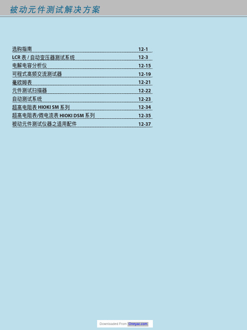
HIOKI儀器產品選購指南说明书
Ⴍ 高速20通道/變壓器L/C/Z/DCR/圈數/短路/平衡掃描測試功能 高速80通道/變壓器L/C/Z/DCR/圈數/短路/平衡掃描測試功能
20通道/變壓器L/C/Z/DCR/圈數/短路/平衡掃描測試功能 3250加LCR錶分析功能 3252 1MHz版
3302加通訊參數測量功能
ٜࠠݴᛌཥݴ๕ / ༊ӻ୕፯ᒅܸی
Ꮠ͜Ⴍ LCD Inverter變壓器(陶瓷電容、線材、PCB)
耐久性測試/耐壓測試/崩潰電壓測試 外部電極螢光燈管(EEFL),背光耐久性/燈管電流測試 交換式電源供應器(SMPS)主變壓器與主動式功率因素修正器
(Active PFC) Choke耐久性測試與電氣特性分析 醫療設備高頻漏電流安規檢驗
ࠫϣ 12-34 12-34 12-34 12-34 12-35 12-35
0.1mΩ ~ 100MΩ 0.1mΩ ~ 100MΩ 0.1mΩ ~ 100MΩ 0.01mΩ ~ 100MΩ 0.01mΩ ~ 100MΩ
3252
20Hz~200kHz
0.1mΩ ~ 100MΩ
3302
20Hz~1MHz
0.1mΩ ~ 100MΩ
Ⴍ 電容量高速檢測 全數位分類,比較器功能,可選無10kHz版 全數位分類,比較器功能
提供高頻高壓交流與直流電源供應的功能,供平面螢光燈(FFL) 與表面傳導電子發射顯示器(SED)裝置分析使用
直流/直流轉換器SMD Power Choke溫昇測試 (直流重疊電流與交流漣波電壓)與電氣特性分析
緩衝電容壽命測試 高壓電容壽命測試 LCD Inverter變壓器(陶瓷電容、線材、PCB)生產線耐壓測試 醫療設備高頻漏電流安規檢驗 車用驅動馬達生產線電暈(Corona)放電檢驗 被動元件(換流器變壓器、陶瓷電容、高壓線材、PCB等) 高頻高壓壽命測試
Kistler 9101C 压电环形力传感器说明书

ForcePiezoelectric force sensorsPiezoelectric ring force transducers for tensile and compression forces from 20 kN to 700 kN9101C _003-473e -08.21Page 1/6© 2020 ... 2021 Kistler Group, Eulachstrasse 22, 8408 Winterthur, Switzerland. Kistler Group products are This information corresponds to the current state of knowledge. Kistler reserves the right to make technical changes. Liability for consequential damage resulting Types 9101C, 9102C,9103C, 9104C,9105C, 9106C, 9107CPiezoelectric force sensors, also known as piezoelectric ring force transducers, for precise measurement of tensile and com-pressive forces in highest resolution.The force sensors are thoroughly tested, but are delivered wit-hout calibration certificate and must be calibrated on site after installation.• Thoroughly tested, delivered without calibration certificate • Linearity including hysteresis ≤±1.5%• Extremely high stiffness • Very compact design • Extremely low threshold• Degree of protection: IP68, dependent on cable • Operating temperature range -40 ... 120°C • No aging, unlimited service lifeDescriptionThe 910x family is a piezoelectric (PE) sensor series for force measurement in the z-direction. The force to be measured is transmitted directly to the quartz element located within the sensor. When subjected to a mechanical load, quartz produces an electric charge that is proportional to that load. An outstan-ding property of quartz is the very low threshold, resulting in a high sensor sensitivity which is extremely linear over the entire measuring range. Thus the behaviour in a certain measuring range is practically identical for all PE sensors, independent of their size.This has three unique advantages:• Overload protection: Even very small forces can be measured with a sensor with a large measuring range, so that overload protection can be considered without loss of signal quality.• High stiffness: To achieve a construction that is as stiff as possible, a larger sensor can also be used without negatively impacting the quality of the measurement signal.• Grouping: Multiple sensors can simply be added together by electrically connecting them in parallel to a single charge amplifier. The output voltage is then proportional to the sum of all acting forces.ApplicationFor monitoring tasks, force sensors are required that can be easily installed in a machine structure. Robust design and re-liability in continuous operation as well as good repeatability of the measured values are further features of these sensors. The choice of a certain size depends on the installation space available on the one hand and on the force shunt ratio of the installation on the other hand.Application examples• Monitoring of press-in forces during assembly, testing, etc.• Monitoring of forces during punching and forming • Measurement of large forces in force shuntSensor MountingRing force transducers are generally used preloaded in a mounting structure.Types 9101C ... 9107CF zDetails about piezoelectric sensors and their installation can be found in the corresponding user's manual on our home-page /force.9101C _003-473e -08.21Page 2/6© 2020 ... 2021 Kistler Group, Eulachstrasse 22, 8408 Winterthur, SwitzerlandTel.+41522241111,****************,. Kistler Group products are This information corresponds to the current state of knowledge. Kistler reserves the right to make technical changes. Liability for consequential damage resulting Technical data--> to ensure the specifications, the sensors must be operated and tested with 20% preload Type9101C9102C 9103C 9104C 9105C 9106C 9107C Nominal force kN 2050100140190330700Load limit kN 2560120160210360770SensitivitypC/N -4.4 ±0.3Linearity incl. hysteresis %FSO ±1.5Repeatability %0.070.020.040.040.050.040.02Reproducibility %0.250.100.100.120.130.110.04Axial stiffness kN/m m 1.6 3.3 5.27.59.815.427.7Lateral stiffness 1)kN/m m 0.310.74 1.3 1.8 2.4 3.97.6Shear stiffness kN/m m 0.400.88 1.5 2.2 2.8 4.69.0Torsional stiffness Nm/°385 1 955 4 93510 26818 46947 184190 330Bending stiffnessNm/°388 2 016 5 18311 22820 82255 355216 950Maximum bending moment 2) (M z = 0), calc.N·m22862173796181 3184 229Temperature sensitivity change ±1.5 (-40°C ... 120°C, Tref = 25°C)%Operating temperature range °C -40 ... 120Insulation resistance (@23°C)W ≥ 5.1013Threshold N <0.01Capacitance pF17±233±452±570±693±6149±15303±20Sensor material Cover plate 1.4821 Coat 1.4542Connector typeKIAG 10-32 neg.Degree of protection (IEC 60529)IP check table on page 4Weightg7203670801573701)Resistantance of the sensor to shear and bending deformation. (Theoretical) assumption: The sensor is fixed at the bottom, the shear force acts at the top, so that the lever length is equal to the toal sensor height. 2)With a pretension of 50% of the nominal force9101C _003-473e -08.21Page 3/6© 2020 ... 2021 Kistler Group, Eulachstrasse 22, 8408 Winterthur, SwitzerlandTel.+41522241111,****************,. Kistler Group products are This information corresponds to the current state of knowledge. Kistler reserves the right to make technical changes. Liability for consequential damage resulting Fig. 1: Dimensions Type 9101C … 9107CTyp d D H s t 9101C 6.514.5814.857.259102C 10.522.51018.67.259103C 1328.51121.657.259104C 1734.51224.657.259105C 2140.51327.657.259106C 26.552.51533.657.259107C40.577.217456.75Dimensions metric [mm]Dimensions Type 9101C … 9107C Bild 1: Abmessungen Typ 9001C … 9071CPretensionPiezoelectric force sensors are always used preloaded in a mounting structure. In general, a preloading force of at least 20% of the nominal force is recommended. The recommen-ded, effective measuring range is thereby achieved and the non-linearities in the lowest load range are eliminated.Reasons for the pretension:• Highest level of linearity and stability• Measurement of tensile and compression forces• Use of the high sensor stiffness for a large frequency range • Ideal force distributionThe pretension must be selected so that the sum of preloading force (F v ) and the process force (±F z ) lies within the measuring range of the sensor at all times (see graphic).Provided it is technologically possible, the average loading of the sensor should be 50% of the nominal force. At this set point, the tolerance with respect to the bending moment is at its greatest (see below, "bending moment").When pretensioning, the force must be measured with the sensor itself. The sensitivity specified in the technical data is toFig. 2: Nominal and measuring rangesbe used here. The mounting surfaces must be flat, stiff and, if possible, ground. Please refer to the user manual for furtherdetails.9101C _003-473e -08.21Page 4/6© 2020 ... 2021 Kistler Group, Eulachstrasse 22, 8408 Winterthur, SwitzerlandTel.+41522241111,****************,. Kistler Group products are This information corresponds to the current state of knowledge. Kistler reserves the right to make technical changes. Liability for consequential damage resulting Bending momentBending moments M B (M x + M y ) increase the stress on one side of the sensor and decrease it on the other. This results in an uneven distribution of the axial force on the sensor, that can distort the measuring results.In extreme cases, this can lead to a one-sided overload of the sensor or loss of the frictional connection, which can destroy the structure or cause it to slip. It ultimately depends on the applied axial force F z which of the two cases occurs first in the event of an impermissible bending moment.Fig. 4: Bending moment as a function of the axial force F zBending moment graphAttentionLateral loads F x,y and/or a torque M z further reduce the measuring range. In case of tight safety margins regarding bending moments and suspected lateral loads or torque, better get in touch with our local sales.ExampleA piezo sensor Type 9103C... is preloaded with F v = 28 kN. What bending moment can be tolerated for process forces in the range F p = 0 ... 33 kN?We use a normalized formula to calculate the allowablebending moment.M B [%] ≤ 100% - 2x | 50%-F z [%] |F z is the total axial force on the sensor, so the sum of the preload F v and the process force F p .The allowed bending moment depends on the applied total force F z and reaches its peak at 50 kN, half the nominal axial force. In this case, when the process force is at 22 kN (28 kN+22 kN = 50 kN).If the force curve in the process is not known, the lowest valueis defined as the maximum load: 122.6 Nm.F v [%] =28 kN100 kN= 28%F p [%] =0 kN 100 kN ... 33 kN100 kN= 0 ... 33%F z [%] = F v [%] + F p [%] = 28 ... 61%M B [28%] = 100% - 2 x | 50% - 28% | = 56%≙ 122.6 NmM B [61%] = 100% - 2 x | 50% - 61% | = 78%≙ 170.8 NmTensile forcesTensile forces are only applicable as long as the preload is higher than the negative force: they reduce the (pre)load on the sensor, which can be measured accordingly.Fig. 5: maximum bending moment depending on preload and processforceFig. 3: Bending moment911C_3-473e-8.21Page 5/6© 2020 ... 2021 Kistler Group, Eulachstrasse 22, 8408 Winterthur, SwitzerlandTel.+41522241111,****************,. Kistler Group products are This information corresponds to the current state of knowledge. Kistler reservesthe right to make technical changes. Liability for consequential damage resultingMeasuring chainMeasure Connect AmplifyConnecting cableAll sensors of type 9101C ... 9107C have a KIAG 10-32 neg.connector and are compatible with all cable connectors KIAG10-32 pos. Only highly insulating coaxial cables with low ca-pacitance may be used to connect piezoelectric sensors. Thesecables generate very little frictional electricity when moving.Kistler uses cables made of high-quality PFA or oil-tight FPM.The IP protection class according to EN60529 on the sensorside is basically dependent on the selected connector. F orIP65 the standard cable connector 10-32 KIAG with knurlednut is used. For increased requirements in harsh environmentsthe industrial version 10-32 KIAG pos. int. is applied, whichcan be welded tightly to the sensor housing if required andachieves IP68.Fig. 6: Measuring chainCompatibilities of cables and charge amplifiersDAQ53A539A573A…574A..5877B…515A…518A…58A…5165A…5167A…KiDAQChannel111‐41‐41111‐81,44,84,…,52min max1631C…PFA0.1100KIAG 10‐32 pos.BNC pos.‐✓✓‐✓✓✓✓✓✓✓1641B…PFA0.1100KIAG 10‐32 pos. 90°BNC pos.‐✓✓‐✓✓✓✓✓✓✓1633C…PFA0.150KIAG 10‐32 pos.TNC pos.‐✓✓‐‐‐‐‐‐‐‐1635C…PFA0.115KIAG 10‐32 pos.KIAG 10‐32 pos.✓‐‐✓‐‐‐‐‐‐‐1957A…PFA, steel braiding0.110KIAG 10‐32 pos.KIAG 10‐32 pos.✓‐‐✓‐‐‐‐‐‐‐1900A23A12..KIAG 10‐32 pos. hex BNC pos.‐✓✓‐✓✓✓✓✓✓✓1900A23A11..KIAG 10‐32 pos. hex KIAG 10‐32 pos. hex✓‐‐✓‐‐‐‐‐‐‐1900A21A120x KIAG 10‐32 pos. hex BNC pos.‐✓✓‐✓✓✓✓✓✓✓1900A21A110x KIAG 10‐32 pos. hex KIAG 10‐32 pos. hex✓‐‐✓‐‐‐‐‐‐‐1983AD…FPM0.15‐20…200°C IP68KIAG 10‐32 pos. int.BNC pos.‐✓✓‐✓✓✓✓✓✓✓1939A…PFA0.120KIAG 10‐32 pos. int.BNC pos.‐✓✓‐✓✓✓✓✓✓✓1941A…PFA0.120KIAG 10‐32 pos. int.TNC pos.‐✓✓‐‐‐‐‐‐‐‐1921…PFA0.120KIAG 10‐32 pos. int.KIAG 10‐32 pos.✓‐‐✓‐‐‐‐‐‐‐1969A…PFA, steel braiding0.510KIAG 10‐32 pos. int.KIAG 10‐32 pos. int.2✓‐‐✓‐‐‐‐‐‐‐1967A…PFA, steel braiding, isolated0.510KIAG 10‐32 pos. int.KIAG 10‐32 pos. int.2✓‐‐✓‐‐‐‐‐‐‐1979A…FPM0.120KIAG 10‐32 pos. int.Fischer 103 Triax‐‐‐‐‐‐‐‐‐‐‐1983AC…FPM0.15IP68KIAG 10‐32 pos. int.KIAG 10‐32 pos. int.2✓‐‐✓‐‐‐‐‐‐‐1 screwed: IP652 welded: IP670.420‐20…200°CIP40IP67IP40PlugscrewedIP65PFA superflexible,drag chain proven0.320‐40…200°CIP67IP40IP67FPM flexible steel hose‐55…200°CPlugwelded1IP67IP40IP65‐20…200°CIP2‐55…200°CPlugscrewedIP65IP40IP53IP2IP4IP65IP65IndustrialAmplifierLaboratoryAmplifier Cable Cable PropertiesLength [m]Temp.RangeIEC/EN60529Connector SensorConnectorAmplifierIEC/EN60529I P4IP2IP2IP6IP679101C _003-473e -08.21Page 6/6© 2020 ... 2021 Kistler Group, Eulachstrasse 22, 8408 Winterthur, SwitzerlandTel.+41522241111,****************,. Kistler Group products are This information corresponds to the current state of knowledge. Kistler reserves the right to make technical changes. Liability for consequential damage resulting Accessories (optional) Type • Special grease 1063• Preloading screw for preloads for compression force measurement, 9422A11 including centering sleeve … 9422A51• Preloading element screw for preloads for pressure and tensile force 9420A11measurement … including mounting accessories 9420A71Mounting accessoriesfor PE force sensor 910xC (optional)• Force distributing ring 95x5• Spherical washer 95x3• Insulating washer 95x7• Force distributing cap95x9Cables (optional)• Connection and extension cables (s. table on page 4)Piezoelectric force sensor Range 0 … 20 kN 1Range 0 … 50 kN 2Range 0 … 100 kN 3Range 0 … 140 kN 4Range 0 … 190 kN 5Range 0 … 330 kN6Range 0 … 700 kN7Ordering key C。
- 1、下载文档前请自行甄别文档内容的完整性,平台不提供额外的编辑、内容补充、找答案等附加服务。
- 2、"仅部分预览"的文档,不可在线预览部分如存在完整性等问题,可反馈申请退款(可完整预览的文档不适用该条件!)。
- 3、如文档侵犯您的权益,请联系客服反馈,我们会尽快为您处理(人工客服工作时间:9:00-18:30)。
Technical Data
Range Calibrated partial range Overload Threshold Sensitivity Variation of the sensitivity with a force acting within the top plate Linearity, all ranges Hysteresis, all ranges Cross talk Rigidity cx cy cz fo (x) fo (y) fo (z) Fx, Fy Fz Fx, Fy Fz Fx, Fy Fz Fx, Fy Fz kN kN kN kN kN kN N pC/N pC/N
Données techniques
Gamme Gamme partielle étalonnée Surcharge Seuil de réponse Sensibilité Variation de la sensibilité sous une force agissant dans la plaque supérieure
Plateforme de mesure à quartz à plusieurs composantes pour mesurer des forces et des moments quelconques. Vaste gamme de mesure et réponse en frequence étendue.
2
6.9253B 5.01
Beschreibung
Die Mehrkomponenten-Messplattform besteht aus einer Deckplatte montiert auf vier Kraftmesselementen. Jedes Kraftmesselement enthält einen vorgespannten Kraftsensor. Der Kraftsensor enthält Quarzringe, welche zwischen zwei Stahlplatten im Sensorgehäuse eingebaut sind. Zwei Schubquarze messen die Kraftkomponenten Fx und Fy und ein Druckquarz die Kraftkomponente Fz einer in beliebiger Richtung auf die Deckplatte wirkenden Kraft. Die den einzelnen Kraftkomponenten proportionalen elektrischen Ladungen werden über Elektroden auf die entsprechenden Steckeranschlüsse geführt. Die 12 Ausgänge der vier Kraftmesselemente sind in der Summierbox so zusammengeschaltet, dass sowohl die 3 Kraftkomponenten Fx, Fy, Fz als auch die 3 Momentkomponenten Mx, My, Mz gemessen werden können. Die vier Sensoren sind masseisoliert eingebaut. Damit werden Erdschleifenprobleme weitgehend vermieden. Die Messplattform ist korrosionsbeständig und gegen Eindringen von Spritzwasser bzw. Kühlmittel geschützt. Zusammen mit einem Anschlusskabel Typ 1687B5 oder 1677A5 entspricht der Bausatz der Schutzart IP 67. Eine Schürze schützt Sensor und Kabel vor mechanischer Beschädigung.
Force – FMD
1 ... 4 9253B...
Mehrkomponenten-Messplattform Plateforme de mesure à plusieurs composantes Multicomponent Force Plate
Quarz-Mehrkomponenten-Messplattform zum Messen beliebig wirkender Kräfte und Momente. Sehr grosser Messbereich und weiter Frequenzgang.
kg
40
Kistler Instrumente AG Winterthur, CH-8408 Winterthur, Switzerland, Tel. (052) 224 11 11
Kistler Instrument Corp., Amherst, NY 14228-2171, USA, Phone (716) 691-5100
Eigenfrequenz
Fréquence propre
Nriebstemperatur Kapazität (pro Kanal)
Température d’utilisation Capacité (chaque canal)
Operating temperature Capacitance (each channel) Fx, Fy Fz
±1 ≤ ±0,5 ≤ 0,5 ≤±2 ≈625 ≈650 ≈250 ≈800 ≈750 ≈850 -20 ... 70 ≈600 ≈600 >1013 >100 IP 67
±1 ≤ ±0,5 ≤ 0,5 ≤±2 ≈750 ≈850 ≈450 ≈580 ≈550 ≈720 -20 ... 70 ≈600 ≈600 >1013 >100 IP 67 90
pF pF Ω MΩ
Isolationswiderstand (20 °C) Résistance d’isolement (20 °C) Insulation resistance (20 °C) Masseisolation Schutzart Gewicht Isolé à la masse Degré de protection Poids Ground isolation Degree of protection Weight
9253B11/B12 9153B21/22
-10 ... 10 -10 ... 20 0 ... 1 0 ... 2 -15/15 -15/30 <0,01 ≈ -7,8 ≈ -3,7 - 15 ... 15 - 15 ... 30 0 ... 1,5 0 ... 3 -20/20 -20/40 <0,01 ≈ -7,8 ≈ -3,7
• •
Technische Daten
Bereich Kalibrierter Bereich Überlast Ansprechschwelle Empfindlichkeit Streuung der Empfindlichkeit bei Kraftangriff innerhalb der Deckplatte Linearität, alle Bereiche Hysterese, alle Bereiche Übersprechen Steifheit
Quartz multicomponent force plate for measuring forces and moments. Large measuring range and wide frequency response.
• •
Deckplatte: Aluminium oder Stahl Plaque supérieure: aluminium ou acier Top plate: aluminum or steel Deckplatten auch mit Gewindelöchern oder T-Nuten erhältlich Plaques supérieures disponibles avec trous taraudés ou avec encoches en “T” Top plates available with tapped holes or T-slots, too. Einfache Montage Montage simple Easy mounting Stabil und zuverlässig Stable et fiable Stable and reliable
9253B23
-12 ... 12 - 12 ... 25 0 ... 1,2 0 ... 2,5 -15/15 -15/30 <0,01 ≈ - 7,8 ≈ - 3,7
000-146m-05.01 (DB06.9253Bm)
Fx, Fy, Fz
% %FSO %FSO % N/µm N/µm N/µm Hz Hz Hz °C
±1 ≤ ±0,5 ≤ 0,5 ≤±2 ≈850 ≈750 ≈250 ≈610 ≈570 ≈570 -20 ... 70 ≈600 ≈600 >1013 >100 IP 67 85
Linéarité, toutes les gammes Hystérésis, toutes les gammes Cross talk Rigidité
Description
La plateforme multicomposante comprend quatre éléments de mesure de force. Chaque élément contient un capteur de force sous précontrainte. Le capteur de force contient des anneaux en quartz qui sont montés entre deux plaques en acier dans le boîtier du capteur. Deux anneaux en quartz sensibles au cisaillement mesurent les composantes de force Fx et Fy, tandis qu’un anneau en quartz sensible à la pression mesure la composantes Fz d’une force agissant dans une direction quelconque sur la plateforme. Les charges électriques proportionnelles à ces composantes sont amenées par des électrodes sur les contacts des connecteurs. Les 12 sorties des quatre éléments de mesure sont branchées dans la boîte de sommation de sorte que les 3 forces orthogonales Fx, Fy, Fz ainsi que les 3 moments Mx, My et Mz peuvent être mesurés. Les quatre capteurs sont montés avec isolement par rapport à la masse. Ainsi les problèmes de circuits de retour par la terre sont largement éliminés. Le jeu de capteurs est résistant à la corrosion et protégé contre la pénétration de projections d’eau et d’agents refrigérants. Ensemble avec un câble type 1687B5 ou 1677A5 le jeu de capteurs correspond au degré de protection IP 67. Un tablier protège la capteur et le câble de tout endommagement mécanique.