ST-32中文资料
NC7ST32资料

Ordering Code:
Order Number NC7ST32M5 NC7ST32M5X NC7ST32P5 NC7ST32P5X Package Number MA05B MA05B MAA05A MAA05A Product Code Top Mark 8S32 8S32 T32 T32 Package Description 5-Lead SOT23, JEDEC MO-178, 1.6mm 5-Lead SOT23, JEDEC MO-178, 1.6mm 5-Lead SC70, EIAJ SC-88a, 1.25mm Wide 5-Lead SC70, EIAJ SC-88a, 1.25mm Wide Supplied As 250 Units on Tape and Reel 3k Units on Tape and Reel 250 Units on Tape and Reel 3k Units on Tape and Reel
DC Electrical Characteristics
Symbol VIH VIL VOH VOL IIN ICC ICCT Parameter HIGH Level Input Voltage LOW Level Input Voltage HIGH Level Output Voltage LOW Level Output Voltage Input Leakage Current Quiescent Supply Current ICC per Input VCC (V) 4.5–5.5 4.5–5.5 4.5 4.5 4.5 4.5 5.5 5.5 5.5 4.4 4.18 4.5 4.35 0 0.10 0.1 0.26 ±0.1 1.0 2.0 Min 2.0 0.8 4.4 4.13 0.1 0.33 ±1.0 10.0 2.9 TA = +25°C Typ Max TA = −40°C to +85°C Min 2.0 0.8 Max Units V V V V V V µA µA mA IOH = −20 µA, VIN = VIH IOH = −2 mA IOL = 20 µA, VIN = VIL IOL = 2 mA 0 ≤ VIN ≤ 5.5V VIN = VCC or GND One Input VIN = 0.5V or 2.4V, Other Input V CC or GND Conditions
STSTM32L496xx系列超低功耗32位ARMMCU开发方案
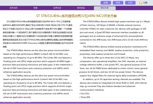
ST公司的STM32L496xx系列是超低功耗32位ARM MCU+FPU,工作频率高达80MHz,具有100DMIPS,集成了多达1MB闪存,320KB SRAM,USB OTG FS,提供多达三个快速12位ADC(5 Msps),两个比较器,两个运放,两个DAC通路,一个内部基准电压缓冲器,一个低功耗RTC,两个通用32位计时器和两个专用马达控制的16位低功耗计时器,七个通用16位计时器和两个16位低功耗计时器.主要用在包括音频和图像等低功耗的应用.本文介绍了STM32L496xx系列主要特性,框图以及时钟树框图和评估板32L496GDISCOVERY Discovery kit框图,主要特性和电路图以及PCB元件布局图.The STM32L496xx devices are the ultra-low-power microcontrollersbased on the high-performance ARM® Cortex®-M4 32-bit RISC coreoperating at a frequency of up to 80 MHz. The Cortex-M4 core features a Floating point unit (FPU) single precision which supports all ARM single-precision data-processing instructions and data types. It also implements a full set of DSP instructions and a memory protection unit (MPU) whichenhances application security.The STM32L496xx devices are the ultra-low-power microcontrollersbased on the high-performance Arm® Cortex®-M4 32-bit RISC coreoperating at a frequency of up to 80 MHz. The Cortex-M4 core features a Floating point unit (FPU) single precision which supports all Arm® single-precision data-processing instructions and data types. It also implements a full set of DSP instructions and a memory protection unit (MPU) whichenhances application security.The STM32L496xx devices embed high-speed memories (up to 1 Mbyte of Flash memory, 320 Kbyte of SRAM), a flexible external memorycontroller (FSMC) for static memories (for devices with packages of 100pins and more), a Quad SPI flash memories interface (available on allpackages) and an extensive range of enhanced I/Os and peripheralsconnected to two APB buses, two AHB buses and a 32-bit multi-AHB bus matrix.The STM32L496xx devices embed several protection mechanisms forembedded Flash memory and SRAM: readout protection, write protection, proprietary code readout protection and Firewall.The devices offer up to three fast 12-bit ADCs (5 Msps), twocomparators, two operational amplifiers, two DAC channels, an internalvoltage reference buffer, a low-power RTC, two general-purpose 32-bittimer, two 16-bit PWM timers dedicated to motor control, seven general-purpose 16-bit timers, and two 16-bit low-power timers. The devicessupport four digital filters for external sigma delta modulators (DFSDM).In addition, up to 24 capacitive sensing channels are available. Thedevices also embed an integrated LCD driver 8x40 or 4x44, with internalstep-up converter.They also feature standard and advancedcommunication interfaces.• Four I2Cs• Three SPIsST STM32L496xx系列超低功耗32位ARM MCU开发方案• Three USARTs, two UARTs and one Low-Power UART.• Two SAIs (Serial Audio Interfaces)• One SDMMC• Two CAN• One USB OTG full-speed• One SWPMI (Single Wire protocol Master Interface)• Camera interface• DMA2D controllerThe STM32L496xx operates in the -40 to +85℃ (+105℃ junction), -40 to +125℃ (+130℃ junction) temperature ranges from a 1.71 to 3.6 V VDD power supply when using internal LDO regulator and a 1.05 to 1.32VVDD12 power supply when using external SMPS supply. A comprehensive set of power-saving modes allows the design of low-power applications.Some independent power supplies are supported: analog independent supply input for ADC, DAC, OPAMPs and comparators, 3.3 V dedicatedsupply input for USB and up to 14 I/Os can be supplied independentlydown to 1.08V. A VBAT input allows to backup the RTC and backupregisters. Dedicated VDD12 power supplies can be used to bypass theinternal LDO regulator when connected to an external The STM32L496xx family offers six packages from 64-pin to 169-pin packages.STM32L496xx系列主要特性:• Ultra-low-power with FlexPowerControl – 1.71 V to 3.6 V power supply– -40 ℃ to 85/125 ℃ temperature range– 320 nA in VBAT mode: supply for RTC and 32x32-bit backup registers – 25 nA Shutdown mode (5 wakeup pins)– 108 nA Standby mode (5 wakeup pins)– 426 nA Standby mode with RTC– 2.57 μA Stop 2 mode, 2.86 μA Stop 2 with RTC– 91 μA/MHz run mode (LDO Mode)– 37 μA/MHz run mode (@3.3 V SMPS Mode)– Batch acquisition mode (BAM)– 5 μs wakeup from Stop mode– Brown out reset (BOR) in all modes except shutdown– Interconnect matrix• Core: Arm® 32-bit Cortex®-M4 CPU with FPU, Adaptive real-timeaccelerator (ART Accelerator™) allowing 0-wait-state execution from Flash memory, frequency up to 80 MHz, MPU, 100 DMIPS and DSP instructions • Performance benchmark– 1.25 DMIPS/MHz (Drystone 2.1)– 273.55 Coremark® (3.42 Coremark/MHz @ 80 MHz)• Energy benchmark– 279 ULPMark™ CP score– 80.2 ULPMark™ PP score• 16 x timers: 2 x 16-bit advanced motor-control, 2 x 32-bit and 5 x 16-bit general purpose, 2 x 16-bit basic, 2 x low-power 16-bit timers (available in Stop mode), 2 x watchdogs, SysTick timer• RTC with HW calendar, alarms and calibration• Up to 136 fast I/Os, most 5 V-tolerant, up to 14 I/Os with independentsupply down to 1.08 V• Dedicated Chrom-ART Accelerator™ for enhanced graphic contentcreation (DMA2D)• 8- to 14-bit camera interface up to 32 MHz (black&white) or 10 MHz(color)• Memories– Up to 1 MB Flash, 2 banks read-while-write, proprietary code readoutprotection– 320 KB of SRAM including 64 KB with hardware parity check– External memory interface for static memories supporting SRAM, PSRAM, NOR and NAND memories– Dual-flash Quad SPI memory interface• Clock Sources– 4 to 48 MHz crystal oscillator– 32 kHz crystal oscillator for RTC (LSE)– Internal 16 MHz factory-trimmed RC (±1%)– Internal low-power 32 kHz RC (±5%) – Internal multispeed 100 kHz to 48 MHz oscillator, auto-trimmed by LSE (better than ±0.25% accuracy)– Internal 48 MHz with clock recovery– 3 PLLs for system clock, USB, audio, ADC• LCD 8 × 40 or 4 × 44 with step-up converter• Up to 24 capacitive sensing channels: support touchkey, linear and rotary touch sensors• 4 x digital filters for sigma delta modulator• Rich analog peripherals (independent supply)– 3 × 12-bit ADC 5 Msps, up to 16-bit with hardware oversampling, 200μA/Msps– 2 x 12-bit DAC output channels, low-power sample and hold– 2 x operational amplifiers with built-in PGA– 2 x ultra-low-power comparators• 20 x communication interfaces– USB OTG 2.0 full-speed, LPM and BCD– 2 x SAIs (serial audio interface)– 4 x I2C FM+(1 Mbit/s), SMBus/PMBus– 5 x U(S)ARTs (ISO 7816, LIN, IrDA, modem)– 1 x LPUART– 3 x SPIs (4 x SPIs with the Quad SPI)– 2 x CAN (2.0B Active) and SDMMC– SWPMI single wire protocol master I/F– IRTIM (Infrared interface)• 14-channel DMA controller• True random number generator• CRC calculation unit, 96-bit unique ID• Development support: serial wire debug (SWD), JTAG, Embedded Trace Macrocell™图1:STM32L496xx系列框图图2:STM32L496xx系列时钟树框图。
STM32入门简易教程

器配置等详细信息。 3、 STM32F103RB 数据手册
a) 产品的基本配置(内置 FLASH 和 RAM 的容量、外设模块的种类和数量等); b) 管脚的数量和分配,电气特性,封装信息和订购代码等。 4、 STM32 开发板手册 与开发板配套的参考资料,有很多经验值得借鉴。 5、 stm32 固件库 a) 相关定义,文档约定和固件库规则; b) 库的架构,安装指南及使用实例; c) 每个外围模块的函数及解释。 6、 开发板原理图 必不可少的硬件电路参考。 7、 互联网 取之不尽的知识宝库。
意法半导体是市场上第一家提供基于 Cortex-M3 内核的无传感器的磁场定向电机控制
解决方案的厂商。这套工具证明 STM32 的内核和专用电机控制外设都有充足的处理能力来 优化驱动器的性能,最小化系统总体成本。STM 微控制器在 25 微秒内即可执行一整套无传 感器三相无刷永磁同步电机(PMSM)矢量控制算法,大多数应用任务占用 CPU 资源比率 小于 30%,为 CPU 执行其它应用任务(如需要)预留了充足的处理能力。永磁电机同步电 机控制解决方案的代码大小少于 16 千字节。
二、重要的参考资料
1、 Cortex-M3 权威指南 宋岩 译 权威资料的精简版,思路清晰,有条理,适合学 Cortex-M3 处理器的所有人。
2、 STM32 技术参考手册 a) STM32 微控制器产品的技术参考手册是讲述如何使用该产品的; b) 包含各个功能模块的内部结构、所有可能的功能描述、各种工作模式的使用和寄存
在性能方面,STM32 系列的处理速度比同级别的基于 ARM7TDMI 的产品快 30%,换 句话说,如果处理性能相同,STM32 产品功耗比同级别产品低 75%。同样地,使用新内核 的 Thumb 2 指令集,设计人员可以把代码容量降低 45%,几乎把应用软件所需内存容量降 低了一半。此外,根据 Dhrystones 和其它性能测试结果,STM32 的性能比最好的 16 位架构 至少高出一倍。
ST32串口应用笔记
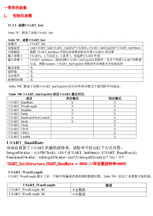
一常用的函数1,初始化函数USART_ART_BaudRate = 9600;//即设置波特率=9600注意下面几个应该是用于在同步模式下的USART_Clock_Disable表示失能USART时钟(指在同步模式下用于控制同步的时钟) USART_Clock_Enable表示使能USART时钟(指在同步模式下用于控制同步的时钟)2 .USART使能函数ART有关的中断使能函数4发送单个数据函数5读出收到的数据二.串口USART1只有两根线USART2 USART3都是后5根线而且都可以重映射到其他的端口。
三数据的处理可以是:1查询方式:if(USART_GetFlagStatus(USART1,USART_IT_RXNE)==SET)接受完成查询:while(USART_GetFlagStatus(USART1, USART_FLAG_TC) == RESET)发送完成查询2中断方式:在中断中处理相应的事四步骤:1设置相应的时钟2设置用做串口的IO口3如果用到中断设置相应的中断(USART_Cmd之前加入中断设置:)4设置USART的有关参数5使能相应的串口(一般加在USART的初始化程序中)例子:1查询法#include "stm32f10x_lib.h"void Delay(vu32 z) //延时函数{vu32 x,y;for(x=z;x>0;x--)for(y=120;y>0;y--);}void RCC_Configuration(void)//时钟设置{//使能UART1时钟和A口时钟RCC_APB2PeriphClockCmd(RCC_APB2Periph_USART1 | RCC_APB2Periph_GPIOA, ENABLE);}void GPIO_Configuration(void) //IO口设置 PA9.10是默认的USART1接口{GPIO_InitTypeDef GPIO_InitStructure;GPIO_InitStructure.GPIO_Pin = GPIO_Pin_9;GPIO_InitStructure.GPIO_Mode = GPIO_Mode_AF_PP;//复用推挽输出GPIO_InitStructure.GPIO_Speed = GPIO_Speed_50MHz;GPIO_Init(GPIOA, &GPIO_InitStructure);GPIO_InitStructure.GPIO_Pin = GPIO_Pin_10;GPIO_InitStructure.GPIO_Mode = GPIO_Mode_IN_FLOATING; //浮空输入GPIO_InitStructure.GPIO_Speed = GPIO_Speed_50MHz;GPIO_Init(GPIOA, &GPIO_InitStructure);GPIO_InitStructure.GPIO_Pin = GPIO_Pin_0 | GPIO_Pin_1; //选择引脚0,1 (选择相应的管脚)GPIO_InitStructure.GPIO_Speed = GPIO_Speed_50MHz; //输出频率最大50M(设置输出的频率)GPIO_InitStructure.GPIO_Mode = GPIO_Mode_Out_PP; //带上拉输出(设置为何种输出或何种输入) GPIO_Init(GPIOA, &GPIO_InitStructure); //初始化PA0,1引脚}void USART_Configuration(void){USART_InitTypeDef USART_InitStructure; //串口参数初始化//初始化参数设置USART_ART_BaudRate = 9600; //波特率9600USART_ART_WordLength = USART_WordLength_8b; //字长8位USART_ART_StopBits = USART_StopBits_1; //一位停止位USART_ART_Parity = USART_Parity_No; //无奇偶校验USART_ART_HardwareFlowControl = USART_HardwareFlowControl_None;//无流控制 USART_ART_Mode = USART_Mode_Rx | USART_Mode_Tx;//打开Rx接收和Tx发送功能 USART_Init(USART1, &USART_InitStructure); //初始化USART_Cmd(USART1, ENABLE); //启动串口}int main()USART_Configuration();//串口初始化while(1){while(USART_GetFlagStatus(USART1, USART_FLAG_RXNE) == RESET);//等待接收完毕i =(USART_ReceiveData(USART1));//把接收到的数据赋给iDelay(5000);USART_SendData(USART1, i); //发送一位数据while(USART_GetFlagStatus(USART1, USART_FLAG_TXE) == RESET);//等待发送完毕}}例子2中断法接收#include "stm32f10x_lib.h"void IT_Configuration(){NVIC_InitTypeDef NVIC_InitStructure;NVIC_PriorityGroupConfig(NVIC_PriorityGroup_0);//选择相应的中断分组NVIC_InitStructure.NVIC_IRQChannel =USART1_IRQChannel;//选择相应的中断通道(这就是要开的中断也就决定了你中断函数写在//那)NVIC_InitStructure.NVIC_IRQChannelPreemptionPriority = 0;//抢占式中断的优先级设置NVIC_InitStructure.NVIC_IRQChannelSubPriority = 0;//响应式中断的中断优先级设置NVIC_InitStructure.NVIC_IRQChannelCmd = ENABLE;//使能中断NVIC_Init(&NVIC_InitStructure); //初始化}void RCC_Configuration(void)//时钟设置{//使能UART1时钟和A口时钟RCC_APB2PeriphClockCmd(RCC_APB2Periph_USART1 | RCC_APB2Periph_GPIOA, ENABLE);}void GPIO_Configuration(void) //IO口设置 PA9.10是默认的USART1接口{GPIO_InitTypeDef GPIO_InitStructure;GPIO_InitStructure.GPIO_Pin = GPIO_Pin_9;GPIO_InitStructure.GPIO_Mode = GPIO_Mode_AF_PP;//复用推挽输出GPIO_InitStructure.GPIO_Speed = GPIO_Speed_50MHz;GPIO_Init(GPIOA, &GPIO_InitStructure);GPIO_InitStructure.GPIO_Pin = GPIO_Pin_10;GPIO_InitStructure.GPIO_Mode = GPIO_Mode_IN_FLOATING; //浮空输入GPIO_InitStructure.GPIO_Speed = GPIO_Speed_50MHz;GPIO_Init(GPIOA, &GPIO_InitStructure);void USART_Configuration(void){USART_InitTypeDef USART_InitStructure; //串口参数初始化//初始化参数设置USART_ART_BaudRate = 9600; //波特率9600USART_ART_WordLength = USART_WordLength_8b; //字长8位USART_ART_StopBits = USART_StopBits_1; //一位停止位USART_ART_Parity = USART_Parity_No; //无奇偶校验USART_ART_HardwareFlowControl = USART_HardwareFlowControl_None;//无流控制 USART_ART_Mode = USART_Mode_Rx | USART_Mode_Tx;//打开Rx接收和Tx发送功能USART_Init(USART1, &USART_InitStructure); //初始化USART_ITConfig(USART1, USART_IT_RXNE, ENABLE);//开接收中断USART_Cmd(USART1, ENABLE); //启动串口}int main(){RCC_Configuration(); //时钟配置IT_Configuration(); //中断配置GPIO_Configuration();//IO口配置USART_Configuration();//串口初始化while(1);}It.c中的函数void USART1_IRQHandler(void){u16 i;if(USART_GetITStatus(USART1, USART_IT_RXNE) != RESET)//检查相应的中断发生没?{i =(USART_ReceiveData(USART1));USART_SendData(USART1, i); //发送一位数据while(USART_GetFlagStatus(USART1, USART_FLAG_TXE) == RESET);USART_ClearITPendingBit(USART1, USART_IT_RXNE); //清除相应的中断标志为}}注意:用中断方式时!要从用户应用程序空间启动,运行用户程序;。
嵌入式系统设计ST32

■ 布尔型
在文件stm32f10x_type.h中,布尔形变量被定 义如下: typedef enum { FALSE =0, TRUE =!FALSE
} bool;
■ 标志位状态类型 在文件stm32f10x_type.h中,定义标志位类型
(FlagStatus type)的2个可能值为“设置” 与“重置”(SET or RESET)。 typedef enum { RESET =0, SET =!RESET
或者HSE/2。倍频可选择为2~16倍,但是其输出频率最大不 得超过72MHz。
■AHB (HCLK) 时钟= SYSCLK = 72MHz APB2(PCLK2)时钟= AHB时钟= 36MHz APB1(PCLK1)时钟= AHB 1/2时钟= 72MHz ADC时钟= PCLK2 1/4 = 9MHz PLL时钟= HSE*9 = 72MHz
备份区域复位。
2.2.3 时钟树
■ P83 图4-3
➢ 系统时钟(SYSCLK)的产生 由SW(时钟配置寄存器RCC_BDCR的D0位和D1位)控制选择。
■ SW[1:0]= 00, HSI,内部
■
01, HSE,外部
■
10, PLLCLK,锁相环,倍频
12. 名为PPP_ClearITPendingBit的函数,其功能为清除外设PPP 中断待处理标志位,例如: I2C_ClearITPendingBit.
三、编码规则
■ 变量 固态函数库定义了24个变量类型,他们的类型和大小是
固定的。 在文件stm32f10x_type.h中我们定义了这些变量:
■ 该函数库是一个固件函数包,它由程序、数据结构和宏组 成,包括了微控制器所有外设的性能特征。
stm32f407数据手册中文

stm32f407数据手册中文STM32F4是由ST(意法半导体)开发的一种高性能微控制器。
其采用了90 纳米的NVM 工艺和ART(自适应实时存储器加速器,Adaptive Real-Time MemoryAccelerator™)。
简介:ST(意法半导体)推出了以基于ARM® Cortex™-M4为内核的STM32F4系列高性能微控制器,其采用了90 纳米的NVM 工艺和ART(自适应实时存储器加速器,Adaptive Real-Time MemoryAccelerator™)。
ART技术使得程序零等待执行,提升了程序执行的效率,将Cortext-M4的性能发挥到了极致,使得STM32 F4系列可达到210DMIPS@168MHz。
自适应实时加速器能够完全释放Cortex-M4 内核的性能;当CPU 工作于所有允许的频率(≤168MHz)时,在闪存中运行的程序,可以达到相当于零等待周期的性能。
STM32F4系列微控制器集成了单周期DSP指令和FPU(floating point unit,浮点单元),提升了计算能力,可以进行一些复杂的计算和控制。
STM32 F4系列引脚和软件兼容于当前的STM32 F2系列产品。
优点兼容于STM32F2系列产品,便于ST的用户扩展或升级产品,而保持硬件的兼容能力。
集成了新的DSP和FPU指令,168MHz的高速性能使得数字信号控制器应用和快速的产品开发达到了新的水平。
提升控制算法的执行速度和代码效率。
先进技术和工艺- 存储器加速器:自适应实时加速器(ART Accelerator™ )- 多重AHB总线矩阵和多通道DMA:支持程序执行和数据传输并行处理,数据传输速率非常快- 90nm工艺高性能- 210DMIPS@168MHz- 由于采用了ST的ART加速器,程序从FLASH运行相当于0等待更多的存储器- 多达1MB FLASH (将来ST计划推出2MB FLASH的STM32F4) - 192Kb SRAM:128KB 在总线矩阵上,64KB在专为CPU使用的数据总线上高级外设与STM32F2兼容- USB OTG高速480Mbit/s- IEEE1588,以太网MAC 10/100- PWM高速定时器:168MHz最大频率- 加密/哈希硬件处理器:32位随机数发生器(RNG)- 带有日历功能的32位RTC:<1 μA的实时时钟,1秒精度更多的提升- 低电压:1.8V到3.6V VDD,在某些封装上,可降低至1.7V - 全双工I2S- 12位ADC:0.41us转换/2.4Msps(7.2Msps在交替模式) - 高速USART,可达10.5Mbits/s- 高速SPI,可达37.5Mbits/s- Camera接口,可达54M字节/s。
ST工具介绍范文

ST工具介绍范文ST工具是指由美国雪铁龙公司(STMicroelectronics)开发和生产的一系列工具。
STMicroelectronics是一家全球领先的半导体解决方案供应商,在汽车、工业、通信、消费电子等领域都有广泛的应用。
ST工具是为了帮助工程师和设计师更方便地开发和测试他们的解决方案而设计的。
ST工具涵盖了各个领域的开发需求,包括软件开发、硬件开发和系统级的验证和调试。
以下是一些常见的ST工具的介绍:1. STM32Cube软件工具:STM32Cube是STMicroelectronics针对其STM32微控制器系列提供的集成开发环境(IDE)。
它提供了全面的软件包,包括驱动程序、中间件和示例代码,可以大大简化软件开发过程。
2. STM8Cube软件工具:类似于STM32Cube,STM8Cube是针对STM8微控制器系列提供的集成开发环境。
它提供了编译器、调试器和库,可以帮助用户快速开发基于STM8的应用程序。
3. STM32Cube扩展工具:STM32Cube扩展工具提供了与STM32微控制器相集成的特殊功能插件。
例如,USB、蓝牙和NFC插件可以使开发人员可以更容易地集成这些功能到他们的应用程序中。
4. STM32射频诊断工具(ST-UDI-DONGLE):这是一款用于射频系统集成调试和测试的USB设备。
它支持各种无线通信标准,如BLE、Wi-Fi 和Zigbee。
5. STM32 Nucleo开发板:Nucleo是一系列功能强大的开发板,用于STMicroelectronics的STM32系列微控制器。
它具有丰富的扩展插槽,用户可以使用各种扩展模块来快速验证和调试他们的解决方案。
6. STM32 Discovery开发板:Discovery是STM32系列微控制器的另一款开发板,具有更多的扩展接口和功能。
它提供了方便的调试功能,例如ST-LINK调试器和USB仿真器。
7. ST-LINK调试器:ST-LINK是STMicroelectronics提供的一款高性能调试和编程解决方案。
STMCU中文官网介绍——STM32、STM8中文资料、技术支持、开发板全部在这里!

STMCU中文官网介绍——STM32、STM8中文资料、技术支持、开发板全部在这里!STMCU中文官网网站的目的是为中国地区用户提供快捷的途径访问、下载关于STM32&STM8的全部产品信息和技术文档,同时也是一个和意法半导体直接沟通关于微控制器的平台。
STMCU中文官网网站内容包含全部STM8家族和STM32家族的英文文档和相关软件库、工具信息,还包括已经翻译成中文的文档和本地工程师精细制作的实战经验(LAT)和视频。
为进一步增强STM32生态系统对广泛市场的支持,我们增加了本地合作伙伴栏目,介绍整体技术方案。
STMCU中文官网设计资源计资源专区信息海量,资源多多。
目前英文文档约500份,软件包超过300份。
STM32单片机中文译文约150份,包含常用的RM (参考手册)、AN(应用笔记)。
为了最大程度满足用户的需求,我们会优先翻译网站上下载和浏览次数多的文档。
MCU实战经验累计超过130份,均来源于ST原厂工程师在日常客户支持工作中的经验总结,兼具"实战性,实用性"。
STM32培训视频已超过60份,包含产品培训和应用专题培训(USB、以太网、电机、音频等),累计时长超过1700分钟!芯片文档·STM32参考手册(Reference Manual)对芯片每个模块的具体描述和功能介绍·STM32数据手册(Data Sheet)芯片引脚定义、电气特性、机械封装、料号定义·STM32勘误手册(Errata Sheet)描述了芯片某些功能的局限性,并给出解决办法·STM32编程手册(Programming Manual)对内核的系统控制块寄存器的描述对芯片闪存的操作指南、读写保护设置,选项字节信息的描述·STM32用笔记(Application Note)针对不同应用主题的描述性文档;常常有与其搭配的固件例程·STM32用户手册(User Manual)一般是对某个软件库的说明文档固件和软件·MCU固件运行在MCU上的程序,包含标准外设固件库SPL和Cube软件包·PC端软件包含PC端各种驱动以及PC端的工具小程序·STM32开发板·评估板(EVALUATION)是功能最全的展示板·探索套件板(DISCOVERY)集成了一些外设模块,但没有评估板的功能丰富·NUCLEO板(NUCLEO )其上的模板芯片分为三种封装(144引脚、64引脚、32引脚)开发工具量产烧录工具STLINKV2STLINKV2-1STVPST-Utility本地化资源·中文译文相关技术文档的中文译文(AN、DS、RM、UM、PM等)·实战经验来源于原厂工程师在日常客户支持工作中的经验总结,涉及通讯接口、电源与复位、IAP和Bootloader、存储器、内核等模块,兼具“实战性、实用性”·培训课件及视频包含产品培训(STM32和STM8)和应用专题培训(USB、以太网、马达、音频等)STM32单片机微信二维码积点兑换会员积分获取规则:1、下载文档+102、观看视频+103、下载视频+204、活动/培训报名+55、活动/培训签到+156、分享+50(需要管理员确认)7、每日签到+2--每天线上能获得的积分最大值为300--附:意法半导体单片机拥有广泛的产品线,包含低成本的8位单片机和基于ARM® Cortex®-M0、M0+、M3、M4及M7内核并具备丰富外设选择的32位单片机。
- 1、下载文档前请自行甄别文档内容的完整性,平台不提供额外的编辑、内容补充、找答案等附加服务。
- 2、"仅部分预览"的文档,不可在线预览部分如存在完整性等问题,可反馈申请退款(可完整预览的文档不适用该条件!)。
- 3、如文档侵犯您的权益,请联系客服反馈,我们会尽快为您处理(人工客服工作时间:9:00-18:30)。
3
CW rotation
2
Note the terminal position.
1
0.6
3.4
1.9
3.5
0.05 3 3.4 1 Resistance code 2 digits 2 t = 0.12 2.1
2 - 0.7
ST-32B, ST-32EB Top adjustment
2 1.5 0.5
Specifications are subject to change without notice. Specifications in this catalog are for reference. The formal specification sheets will be submitted upon request. Document Number: 58009 Revision: 06-Mar-06 For technical questions contact: copalsupport@ 3
ST-32A, ST-32EA Top adjustment
2 1.5 0.5
1
Cross slot for a 0 bit driver, depth: 0.45 Production date code & Lead (Pb)-free Identification mark 1 digit (Location reversed every 2 years)
0.05 3 3.4 1 Resistance code 2 digits 2 t = 0.12 2.1
2 - 0.7
Specifications are subject to change without notice. Specifications in this catalog are for reference. The formal specification sheets will be submitted upon request. Unless otherwise specified, tolerance: ± 0.3 (Unit: mm)
Adjustment 3 2.4 2 - 0.6 1.4 1
4.7
2.6
1.9
Resistance code 2 digits
t = 0.12
1 2
PACKAGING SPECIFICATIONS
Taping packaging specifications
Taping version is packaged in 500 pcs. per reel. Orders will be accepted for units of 500 pcs., i.e., 500, 1000, 1500 pcs., etc. ST-32TA, ETA, TB and ETB versions are boxed with 4 reels (2000 pcs.). ST-32TG, ETG, TH and ETH versions are boxed with one reel (500 pcs.). Maximum number of consecutive missing pieces = 2 Leader length and reel dimension are shown in the diagrams below.
EMBOSSED TAPE DIMENSIONS
Empty Filled Empty
REEL DIMENSIONS
(Conforms to JIS C 0806-3) (In accordance with EIAJ ET-7200A)
(Unit: mm)
13 +1 0 (TA/TB/ETA/ETB) 13.4 ± 1 (TG/TH/ETG/ETH)
2.5
3
1 Direction of feed
5.5 max.
3
1 Direction of feed
Vinyl bag packaging specifications
Unit of bulk in vinyl bag packaging is 100 pcs. per pack. Boxing of bulk in vinyl bags is performed with 500 pcs. per box.
ENVIRONMENTAL SPECIFICATIONS
Test item Thermal shock Test conditions - 65 ∼ 125 °C (0.5 h), 5 cycles - 10 ∼ 65 °C (Relative humidity 80 ∼ 98 %), 10 cycles, 240 h 981 m/s2, 6 ms 6 directions for 3 times each Amplitude 1.52 mm or Acceleration 196 m/s2, 10 ∼ 2000 Hz, 3 directions, 12 times each 70 °C, 0.125 W, 1000 h - 55 °C, 2 h [ΔR/R ≤ 1 %] [S.S. ≤ 1 %] Specifications [ΔR/R ≤ 2 %] [S.S. ≤ 1 %] [ΔR/R ≤ 2 %]
元器件交易网
ST-32
Vishay
Surface Mount Cermet Trimmers (single turn)
FEATURES
• • • • Lead (Pb)-free soldering, Cadmium-free Top and side adjustment styles Rotor with a cross slot for ease of adjustment Leaded terminals provide strong as adhesive strength against P.C.B. bending • J-hook, Gull wing and leaded terminal configurations • Sealed / Washable • RoHS compliant
ST-32G, ST-32EG Side adjustment
Cross slot for a 0 bit driver, depth: 0.45 Production date code & Lead (Pb)-free Identification mark 1 digit (Location reversed every 2 years) 3.6 1.5 0.5 3.5 0.2
Cross slot for a 0 bit driver, depth: 0.45 Production date code & Lead (Pb)-free Identification mark 1 digit (Location reversed every 2 years)
1
3.4
1.9
4.4
4 ± 0.1 2
1.75 ± 0.1
8 ± 0.1
Ø
2
Ø 60 +1 0 (TA/TB) Ø 80 ± 1 (TG/TH)
End
Head
0.4 ± 0.1 Installation example (ST-32H, EH)
5.5 ± 0.05
5.5 ± 0.05
12
Installation example (ST-32A, EA)
15.4 ± 1 (TA/TB/ETA/ETB) 17.4 ± 1 (TG/TH/ETG/ETH)
ST-32TA, TB, ETA, ETB
1.75 ± 0.1 8 ± 0.1 4 ± 0.1
Ø 5 1.
ST-32TG, TH, ETG, ETH
0.3 ± 0.1
2 ± 0.05
2 ± 0.1
.1 +0 0
元器件交易网
ST-32
Surface Mount Cermet Trimmers (single turn)
Vishay
DIMENSIONS in millimeters OUTLINE DIMENSIONS
Unless otherwise specified, tolerance: ± 0.3 (Unit: mm)
For technical questions contact: copalsupport@
2
元器件交易网
ST-32
Vishay
Surface Mount Cermet Trimmers (single turn)
DIMENSIONS in millimeters
DIMENSIONS in millimeters RECOMMENDED P.C.B. PAD OUTLINE DIMENSIONS
ST-32A, G, EA, EG
1.6
ST-32B, H, EB, EH
(Unit: mm)
1.6
1.5
0.9
0 1
4.6
1.2
1.2
0.8 3.2
1.2
For reflow soldering
ST-32H, ST-32EH Side adjustment
Cross slot for a 0 bit driver, depth: 0.45 Production date code & Lead (Pb)-free Identification mark 1 digit (Location reversed every 2 years) 3.6 1.5 3.5 0.5 0.2
1.2
0.8 3.2
1.2
Note) The zero point is the center of mounting.