u-ec5下载软件使用说明
U2EC5 USB2.0存储盒子套件用户指南说明书

USB2.0 Storage Enclosure kitU2EC5User’s GuideRev.1.0July 2001Contents1. Before installation (3)1-1. Package Confirmation (3)1-2. System Requirements (3)1-3. Restrictions (3)1-4. Front/Back Side Function (4)2. Setup (5)2-1. Mounting a drive (5)2-2. Connectiong a power cable and USB cable (8)2-3. Installing USB driver (8)3. Removing the U2EC5 (15)4. Disk Formatting and Partitioning Utility (16)5. Registration and Tech-support (19)Appendix (20)21. Before installation1-1. Package ConfirmationCheck package contents:•U2EC5 5 inch case•AC Cable•One USB2.0 Compliant cable(1m)•Mounting screws•Support Software CD-ROM•Installation guide(This document)•Software License AgreementNOTEIf any of these items are missing from the retail package, contact your supplier immediately.1-2. System Requirements•Windows 98SE/Windows Me/Windows 2000•PC with built-in USB port or with our add-on USB PCI board/PC card1-3. RestrictionsTo enjoy USB2.0 High-Speed performance, our add-on USB2.0 PCI board(PCIU2)/PC card(CBU2) and its EHCI driver are required. No other USB2.0 PCI boards/PC Cards or drivers are guaranteed.31-4. Front/Back Side Function[Front Side](1)Front cover[Back Side][Front Side](1)Front coverYou have to remove this cover when you mount a 5 inch drive.(2)Power LEDWhen this drive is powered, this green power LED comes on.(3)Power switchBy pushing this button, you can turn a drive on or off.[Back Side](1)Power cable inletConnect the bundled power cable.(2)FanThe fan is used to force out air in the U2EC5 to keep it cool.(3)USB portConnect the bundled USB cable to the PC.(4)Audio output(LINE OUT)If you connect a speaker with an amplifier, you can listen to sound.452. SetupTo set up the U2EC5, follow the steps:2-1. Mounting a drive(1)Release the screw at rear panel.Then, slide out the inner case by pushing back panel.(2)Slide the top cover off inner case.(3)Push the hook on front panel to release front cover if you mount a 5 inch drive. If not, you don’tneed to release it. In such a case, proceed to step (6).6(4)Set [MASTER] position in jumper setting. Then, slide a 5 inch drive such as a CD-ROM into inner case and connect IDE cable, power cable and analog audio cable(red-colored line is R ; white-colored line is L).Power cableIDE cable Set [MASTER] positionAudio cable (5)Fix the drive to inner case by screws. Then, replace the top cover and slide back the inner case intoenclosure. You have finished mounting a drive. Proceed to Chapter 2-2.(6)If you mount a 3.5 inch hard drive, set [MASTER] position in jumper setting. Then, connect IDE cable, power cable.Power cable IDE cable Set [MASTER]position (7)Fix the drive to inner case by screws. Then, replace the top cover and slide back the inner case intoenclosure. You have finished mounting a drive. Proceed to Chapter 2-2.782-2. Connectiong a power cable and USB cableConnect a power cable to an outlet. And connect the bundled USB cable to the USB port on yourPC as shown below.2-3. Installing USB driver(A)For Windows 2000, Windows Me usersTurn on the U2EC5 case. The drive will be detected and the driver will be installedautomatically. If the installation was successful, you can find the added icon in [My Computer]. The example figure below shows a CD-ROM drive is added (Drive letter depends on yoursystem).NOTE:If you are a Windows 2000 user, you must belogged on as Administrator or have adminis-trator privileges to install the driver.(B)For Windows 98SE usersa)Turn on the U2EC5 case. The following window appears. Insert the Support Software CD-ROM and.click [Next]b)Select [Search for the best driver for your device.(Recommended)] and click [Next]9c)Select the [CD-ROM drive] option and click [Next].d)Make sure RTUS2ST.INF was found and click [Next]10e)When the driver has been copied onto your system, the following window appears. Click [Finish].f)The following window appears. Click [Next].g)Select [Search for the best driver for your device.(Recommended)] and click [Next].h)Select the [CD-ROM drive] option and click [Next].i)Make sure RTUS2STS.INF was found and click [Next].j)When the driver has been copied onto your system, the following window appears. Click [Finish].If the installation was successful, you can find the added icon in [My Computer]. The example figure below shows a CD-ROM drive is added(Drive letter depends on your system).3. Removing the U2EC5(1)When you click on the removal icon on the task tray, a pop-up menu similiar to the following willappear. Select it.(OS:Windows 98SE)(2)When the message box saying [the device can now be safely removed from the system] appears,click [OK]. You can remove the U2EC5 from the PC safely.4. Disk Formatting and Partitioning UtilityWith the bundled utility, you can change file system or format a storage device. Follow the steps below to use the utility(The device information depends on a device in the U2EC5).1.Make sure the U2EC5 is connected and powered on.2.Insert the support software CD-ROM into the CD-ROM drive.3.Open [My Computer] and double click the CD-ROM drive icon. Double click the FRFMTW9X.EXEfile at the [Formatter] folder in the [Rhd-U2] folder.4.[Select the Drive] dialog will appear. Select the drive and click [Select].(NOTE)1.The drive list window shows all the devices connected to SCSI, IDE besides USB interface on yourPC.2.You can format a storage device such as a HDD, Zip, MO with this utility. But, you can’t format aCD-R, CD-RW, DVD-RAM.3.This utility runs only on Windows 98SE, Windows Me.4.If you use Windows 2000, you have to use [Disk Management] in Windows 2000. If you format anover 32GBytes HDD, you have to select [NTFS] file system. If you select [FAT32], you will fail to format the HDD.For more information, refer to Windows 2000 Help file.5.[Format Utility] dialog will appear. Select [Initialize/Format media] from the [Edit] menu.6.[Initialize/Format Media] dialog will appear. Select format type. Then, click [OK].(NOTE)You can’t do low level formatto the U2EC5. Never check this[Low level format] option.7.If you selected IBM-PC/AT FDISK Format, the message box saying [You should create partition next] will appear. Click [OK]. Then, you will see the screen shown in the step 5. Select [CreatePartition] from the [Edit] menu. [Create Partition] dialog will appear as shown to the right.Select File System from the list box and set Partition size, using the slider bar.If you format the drive, check the [Format Drive] option.Then, click [OK] to create partition. If you selected Super FD format, select File System from the list box and click [OK].8.The confirmation message box will appear. Click [OK].9.The dialog shown in the step 5 will appear. Select [Quit] from the [Edit] menu. The message box will appear. Click [OK].Then, remove the U2EC5 and reconnect it for your information to take effect. (See Chapter 3 for how to remove the U2EC5).5. Registration and Tech-support5-1. How to RegisterWe highly recommend to register yourself as our customerthrough our on-line registration.(1)On the Internet, access our site. (/english/)(2)Follow window menu guide to register.(3)Fill out and submit the registration form.5-2. Software Update and Support-Software Update-The latest driver and application software are subject to change for improvement or bug fix. You can download the latest version from our web site.(/english/)-Technical Support-You can reach our Tech support staff at the following:RATOC Systems International,Inc. Tech Support(Open : Mon - Fri 9:30AM - 5:00PM PST)Address : 1933 O’Toole Avenue Suite A109, SanJose, CA 95131, U.S.A.Phone : (408)955-9400Fax : (408)955-9402E-mail:************************.jpWeb : /english/AppendixCopyright©2001 RATOC Systems,Inc. All rights reserved. No part of this publication may be reproduced,stored in a retrieval system, or transmitted in any form or by any means(electronic, mechanical, photo-copying, recording or otherwise) without the prior written consent of RATOC Systems,Inc.Trademarks-Windows is a registered trademark of Microsoft Corporation.-Other brand and product names may be registered trademarks or trademarks of their respectiveholders.ChangesThe information in this User’s Manual is furnished for information only and is subject to changewithout notice.RATOC Systems,Inc. reserves the right to make changes in the product design orproduct improvements without reservations and without notification to its users. RATOCSystems,Inc. assumes no responsibility or liability for any errors or inaccuracies that may appear in this document.FCC StatementThis equipment has been tested and found to comply with the limits for a Class B digital device, pursuantto Part 15 of the FCC Rules. These limits are designed to provide reasonable protection against harmfulinterference in a residential installation. This equipment generates, uses and can radiate radio frequencyenergy and, if not installed and used in accordance with the instructions, may cause harmful interferenceto radio communications. However, there is no guarantee that interference will not occur in a particularinstallation. If this equipment does cause harmful interference to radio or television reception, which canbe determined by turning the equipment off and on, the user is encouraged to try to correct theinterference by one or more of the following measures:(1) Reorient or relocate the receiving antenna.(2) Increase the separation between the equipment and receiver.(3) Connect the equipment into an outlet on a circuit different from that to which the receiver isconnected.(4) Consult the dealer or an experienced radio/TV technician for help.Changes or modifications not expressly approved by the party responsible for compliance may result inthis unit not complying with FCC Rules Part 15.。
U-EC5使用手册
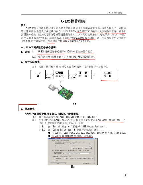
图15 7、菜单-Program(编程操作)如图 16
图 16 7.1 Read(读出)
将芯片内 FLASH 的内容读到缓冲区如图 17。
图 17 7.2 Write(写入)
将缓冲区的内容写到芯片的FLASH, 如图18。
图18
6
7.3 Lock(加密) 将芯片加密。
7
U-EC5 操作指南
9.1.5 是否允许自动添加序列号 此功能是为生产的产品在内存区的指定地址上注明生产的序列号。
9.1.6 序列号长度 指定所写字节的长度。
9.1.7 存储地址 指定序列号所要保存的地址。
9.1.8 异或值及初始号码 Fra bibliotek此两项的值异或操作后存入指定的地址。
9.1.9 自动处理操作 选择自动处理时所执行的命令。
图8
15、
用户需点击菜单栏“Project\Options for Target …”选项,在出现的新对话框中点击菜 单栏的“Debug”选项,进行如下设置,以进行 C8051F 系列 MCU 的硬件调试。如图 9
15.1 选择“use Silicon Laboratories C8051FXXX” 15.2 选择“Go till main” 15.3 在“Setting”中设置端口
1.2 软件运行环境:Microsoft Winodows 98/2000/NT/XP。 2. 硬件安装操作
2.1 按图 1 进行硬件连接(PC 机会自动识别,用户继续下一步操作)。
图1 3. 使用操作
*若用户在 IDE 中使用 U-EC5,则按以下步骤操作: 3.1 打开集成开发环境“Silicon Laboratories IDE.exe” 3.2 在菜单栏中点击“Options”选项,在其下拉子菜单中点击“Connection Options …” 选项,出现如图 2 的对话框,进行如下设置: 3.2.1 在“Serial Adapter”栏选择“USB Debug Adatper”。 3.2.2 在“Debug Interface”栏中选择调试接口类型。 ● 当 MCU 为:C8051F00X/01X/02X/04X/06X/12X/2XX 系列时,选择 JTAG; ● 当 MCU 为 C8051F3XX 系列时,选择 C2。
瑞友天翼客户端操作指南V5.1

瑞友天翼客户端操作指南西安瑞友信息技术资讯有限公司2012年10月版权声明本书著作权属于西安瑞友信息技术资讯有限公司所有,在未经本公司许可的情况下,任何单位或个人不得以任何方式对本书的部分或全部内容擅自进行增删、改编、节录、翻译、翻印、改写。
西安瑞友信息技术资讯有限公司2012年10月目录1、首次登陆下载并安装客户端 (4)2、使用IE浏览器方式访问 (7)3、使用瑞友天翼应用虚拟化客户端方式访问 (8)4、瑞友天翼虚拟化客户端系统设置 (10)4.1、基本设置 (11)4.2、打印设置 (11)4.2.1、打印输出类型 (11)4.2.2、指定打印机 (12)4.2.3、纸型选择 (12)4.2.4、打印操作注意事项说明 (12)4.3、本地特性 (13)4.3.1、远程窗口特性设置 (14)4.3.2、本地资源特性设置 (14)5、本地文件打开方式设置 (14)1、首次登陆下载并安装客户端1.1、客户端在第一次使用时,需要在IE浏览器上输入网址域名或公网IP地址,登陆到应用服务器访问首页,在此下载并安装瑞友天翼客户端软件,如下图:1.2、从瑞友天翼WEB界面,点击[安装GWT客户端],会出现如下图提示:1.3、可选择【保存】到本地计算机后,点击CASWebClient.exe运行安装(注意:本客户端程序只有4MB左右(根据您服务器版本不同稍有差异),可通过下载保存到本地来观察带宽速度,如带宽速度达不到20kbps,需尽快联系网络管理员排除网络故障),如网络带宽足够,可直接点【运行】,会直接下载到本机临时文件后并会弹出安装界面,如下图:1.4、点击【运行】,即可安装GWT5.1客户端,选择安装语言,点击【确定】,如下图:1.5、弹出瑞友天翼应用虚拟化安装向导,如下图:1.6、点击【下一步】进行安装,选择【我接受协议】后,点击【下一步】,如下图:1.7、选择安装路径,一般默认路径,无需修改,点击【下一步】,见下图:1.8、安装完成,点击【完成】,以上通过向导,即可完成全部安装工作。
点点电子USB_DEBUG_ADAPTER使用手册

点点电子工作室EC6/USB Debug Adapter 产品说明书目录目录 (2)一、产品概述 (3)1.1 C8051F调试工具简介 (3)1.2 产品性能 (4)1.3 仿真器接口定义 (4)二、在KEIL下使用USB Debug Adapter (5)三、使用批量下载工具 (7)3.1 U-EC5中文下载程序 (7)3.2 Silicon Laboratories Flash Utility (8)3.3 Silicon Labs MCU Production Programmer (9)四、EC6固件更新 (10)一、产品概述1.1 C8051F调试工具简介C8051F系列单片机是Silabs公司推出的一系列增强型51单片机,其指令集兼容传统MCS-51。
内核采用增强型CIP-51,其最大指令速率达到100MIPS,丰富的外设以及灵活的交叉开关,形成一个SOC,为目前绝大多数8位单片机所不能比拟。
C8051F单片机目前正在高速增长,由于具有兼容传统51的先天优势,已经被越来越多的爱好者和设计者所青睐,C8051F单片机已经进入大学课堂,成为大学单片机教材。
C8051F单片机开发工具经过多个版本发展,经历了并口、串口、USB-串、USB。
目前,以及发展到真正的USB通信,不再使用串并口或者虚拟串口。
C8051F开发工具还包括U-PDC等,但是使用最方便、最普遍的仍然是U-EC6。
点点电子工作室开发的这款U-EC6采用国外原装电路改进而来,可实现支持单步、连续单步、断点、观察点、堆栈监视器, 可以观察/修改存储器和寄存器, 下载程序到Flash存储器等功能,兼容国内任何一家的C8051F调试工具。
多次得到高校的批量订单,使用效果反馈良好。
请定期去官方网站版本软件,以达到更好的使用效果。
也可以在国内代理商下载。
1.2 产品性能 - 可与Keil 、silabs 官方推出的各种软件,如Silicon Laboratories IDE ,FLASH UtilityProgrammer ,Product Programmer ,新华龙U-EC5中文下载程序软件等软件实现无缝连接调试。
2021 ECO 5.0L 驱动系统安装说明说明书

Please visit for the most current instruction and warranty information.PLEASE READ ALL OF THE FOLLOWING INSTRUCTIONS CAREFULLY PRIOR TOINSTALLATION. IF AT ANY TIME YOU DO NOT UNDERSTAND THE INSTRUCTIONS, PLEASE CALL THE FORD PERFORMANCE TECHLINE AT 1-800-367-3788The use of a vehicle hoist is recommended for this installation. If you do not have access to one, use a hydraulic floor jack and jack stands to safely raise the vehicle.CAUTION: JACK STANDS MUST BE USED ON A LEVEL SURFACE AND BE SECURELY SEATED. FAILURE TO DO SO MAY RESULT IN PERSONAL INJURY OR VEHICLE DAMAGE 2021 ECO 5.0L Drivetrain Installation InstructionsSection Topic1.0 Introduction .…………………………………………………………………………………………………..2.0 Overview .……………………………………………………………………………………………………..3.0 Included/Possibly Required Components ..……………………………………………………………….1.0 IntroductionThis kit was developed by Ford Performance in order to allow performance enthusiasts the ability to install a 5.0L Gen3 Mustang Crate Engine (Fordequipment up to, and including, OBD I equipped vehicles. This Kit is NOT intended for fitment into OBD II equipped vehicles. Note: Cruise control is not available with this system.vehicle speed signal from CAN bus circuit. Analog gauges will require either a CAN translator box or a drive shaft speed3.7 Accelerator Pedal Position Sensor (APPS)•The Accelerator Pedal Assembly includes a pair of Integrated Pedal Position Sensors (APPS1/APPS2). This pedal has electrical properties designed specifically for correct interface with PCMengine operation.3.8 Evaporative System•The Purge Solenoid is required to control the flow of fuel vapors from the Carbon Canistor. It is required toEvaprotive Canistor ConnectionsEvaprotive Canistor Mounting Options3.9 Brake Aspirator•The Brake Aspirator utilizes a flow of air thru an orifice to increase the vacuum to the Brake Booster. The flow of air from the induction tube to the intake manifold is a specific calibrated volume that is accounted for in the engine contol software. The use of the Brake Aspirator is required for proper engine operation.3.10 Passive Anti-Theft System Module (PATS)The PATs module is matched to your Powertrain Control Module (PCM) as received. The PCM will not allow the starter to crank the engine without communications with the specific matched PATs module.The PATs module stores your hardware configuration for use by the PCM (tire circumference and axle ratio) Ford Performance Pro Cal Flash ToolA programing tool is included in the kit to configure your powertrain.Crank Position Sensor profile (also known as the misfire profile learning).3.14 Plastic Bag of Assorted Items3.15 Air Cleaner Assembly with Integral Mass Air Flow SensorThe AAT must be installed in the vehicle forward of the radiator or other heat exchangers.The installation location must be in the flow of fresh air to provide optimum performance as it effects the calculation of the delivered spark and fuel.3.17 Controls Pack Wiring Assembly•Connects to vehicle battery and inline connector on engine harness.•Contains Ford Performance Power Distribution Box (FPPDB) and High Power inline fuse.•Electrical connections to Accelerator Pedal (APPS) and Clutch Switch (CBT).•Wire leads for Ignition Switch & Starter.•Data Link Connector for reading Diagnostic Trouble Codes (DTCs).•Check Engine/Malfunction Indicator Lamp (MIL) for visual indication of engine control system fault code4.0 Pre-Installation of Harnesses and Drive Train4.1 Planning- Taking a few moments to plan your installation will make the installation and completion of the drivetrain much easier. To assist you, below are the external dimensions of the engine with the exhaust manifoldsinstalled.Total Width (without the AIS): 768mmTotal Length (without the exhaust or AIS) 1370mm:Total Length with AIS (without exhaust):1520mmMount the Floor Shifter and route the Shifter Cable.The Shifter Cable will need to be routed so the cable mounts to the Transmission with the cable end to thefront on the left side of the Transmission.Picture shown is for reference only to assist in component placement suggestionsThe following is a list of key factors to consider before any of the installation takes place:• PCM mounting location is limited by the length of the PCM lead of the Engine Harness (located on the rightfront corner of the Engine). The PCM Connector Lead measures 22 inches from the lower edge of the right Valve Cover. This will dictate the location of where the PCM will need to be mounted.• Ford Performance Power Distribution Box must be mounted, in the engine compartment, within 60 inches ofthe vehicle battery or positive battery post if you have a trunk mounted battery as dictated by the battery+/ ground lead lengths of the controls pack wiring harness.• Lay out the harness and components first in order to ensure that the wiring leads will reach everywhere youintend them to. This is a good check before you drill any holes or mount any components!• Plan on a good location to mount the EVAP Canister. Traditionally, they are located under the rear of theVehicle, close to the Fuel Tank.• If your transmission tunnel is very tight, decide how you will check your transmission fluid level after the firststart-up. You may need to fabricate an access hole to check it from above then, re-seal the hole with rubber body plug or a removable panel. If you test fit your drivetrain, that will be a good time to determine your needs.Fuse Box/PCM LocationAir BoxBattery BoxMAFFuel PressureRegulator5.1. Assembling the Drive Train- Remove the Engine (including all the components) from the packaging, and inspect the Engine for damage.Inspect the Crankshaft Sensor Ring for damage. If the Crankshaft Sensor Ring has beendropped, or has any visual damage, it must be discarded. A slight bend in any tooth of the ringcould result in a “no start” condition as this ring triggers the Crank Position Sensor (CPS).Place the Crankshaft Sensor Ring on the Crankshaft being sure the Locator Pin engages theHolding ToolIMPORTANT NOTEThe Ford 10R80 Automatic Transmission is a “sealed”, non-service unit. There is no Transmission Fluid Dip Stick Tube. Therefore, it is VERY important that you follow the Instructions below to initially fill the Transmission. You will need to check the fluid level AFTER the first start-up. Be sure you allow room in the vehicle to be able to execute the check.Install the Transmission Fluid Cooler Tubes and the new bolt to the Transmission on the forward left side of the Transmission.Torque: 18 lb/ft (25 Nm)Attach the Cooler Lines to the Bell Housing Stud.- Place a Exhaust Manifold Gasket on the Manifold Studs.- 1. Position the Catalytic Converter onto the Engine and finger-tight the nuts. - 2. Tighten the nuts in the sequence shown.- Install the Drive Train into the Vehicle.Install the Brake Aspirator.NOTE:It is very important that this Brake Aspirator is utilized as it increases the vacuum available to the Brake Booster as well as being important to the tuning in the PCM.To the EVAP CanisterIf not already present, install the Canister Purge Valve. The yellow colored hose on the right side of the above photo needs to be run to the EVAP Canister.Connect the Fuel Line from the Fuel Pressure Regulator.Connect your cooling system.BATTERYENGINESTARTER ALTERNATORSuggested Battery Cable diagramConnect the Battery positive to the Starter and Alternator.Ground the Engine to the Chassis.Pay close attention to the vehicle grounds. Many times, electrical Issues can be traced back to insufficient ground circuits. Ensuring your vehicle is well grounded now, will save you time and- Install and adjust the Shifter CableUnlock the adjuster.6.0 Control Pack Connection Details Item Connector #A -B -C C160AD C2040- -Inside the VehicleFigure 1b – Transmission Harness6.1 Engine Harness Routing(Automatic)Front View of Engine:6.3 Controls Pack Harness Installation InstructionsNOTE: To avoid electrical shock and/or damage to sensitive electrical control system components, before beginning any work, remove the vehicle’s negative Battery terminal and place a rag or towel between it and the Battery negative Post. The negative Battery terminal is not to be reinstalled until the last step of installation.1. Identify proper mounting location for the PCM, Power Distribution Box (Item A) & Inline Fuse Holder. Locate the PCMconnector (Item L) on the Engine Harness as indicated in Figures 2 and 3 by the “START HERE” arrow.- Shifter Lever Switch Pigtail.Pin 1 connect to Pin 4Pin 2 connect to Brake Switch Output (12v when the Brake Pedal is depressed)Pin 3 NOT USEDPin 4 connect to Pin 1Pin 5 Ground to ChassisPlug the Shifter in. Wiring the Shifter in this manner allows the Park Release to operate as intended in the 2020 Mustang. When the Brake Pedal is depressed, It will allow you to shift from Park. It will not operate when in any other Gear is selected.6.4 6-way I/P Pigtail Connection DetailsThe 6-way pigtail is to be connected according to the chart below. See also the diagrams on the following pages for illustrations of wire connection points, based on the ignition/starter switches that you intend to use. Setup A uses separate toggle switches for ignition and starter inputs, while Setup B uses an ignition cylinder with a key.WireColorGN Provides +12V to the fuel pump-Apply +12V to send a request to the PCM to energize the starterLight Blue6.4.5 Blunt Lead 5 – Ignition Relay Trigger (Light Green):Set-up A:Set-up B:7.0 Ford Performance Power Distribution Box Installation7.1. Before you start, yourecommended), one from Battery to fuse holder, the other one from fuse holder to FPPDB.7.2. Carefully remove the nut and washers on both terminals of the in-line fuse holder and set aside.7.3. Use one of your battery cables and place the eyelet onto one of the two in-line fuse holder terminals, then one of thewashers, and then tighten down with one of the two nuts.7.4. Locate the power terminal of the side of FPPDB, notice there is a battery positive blunt lead eyelet already attached8.0 Fuel SystemThe PCM is calibrated for a return style fuel system as shown below.- Included pressure regulator is set at the factory to 75psi. Do not try to adjust it.- Use only AN type fuel fitting to interface with OEM fuel rail.- Fuel Pump must be capable of 160 liters per hour flow at 75 psi..Fuel pump requirements: 160L/Hr minimum at 75psiA common and often overlooked problem is the location of the fuel pump or pumps. Optimally, the fuel pump should be mounted IN THE TANK to reduce the possibility of pump cavitation. Cavitation is essentially localized boiling caused by a reduction in pressure, generally occurring on the inlet side of a pump. This localized boiling results in fuel vapor bubbles which will reduce the volume of fuel the pump is capable of delivering to the engine. Any reduction in pressure or increase in temperature at the inlet side of the pump increases the chances that cavitation will occur. For this reason, it is always best to either have the pump inside the tank immersed in fuel or (in the case of an external pump) gravity fed, which will increase the pressure on the inlet side of the pump. If the fuel pump has to “pull” the fuel, this will result in a reduction in pressure at the fuel pump inlet potentially allowing cavitation and, thus, vapor bubbles to develop. These vapor bubbles are then drawn into the fuel pump and exit the high-pressure side of the fuel pump as compressed vapor. They travel the entire length of the fuel system and are expelled through the fuel injector. This can cause issues ranging from stumbles and hesitations to engine damage due to insufficient fuel delivery and lean A/F ratios. Sometimes this problem can characterize itself by only appearing when the weather gets warmer, which can confound the diagnosis of the issue. In certain cases, it may seem to only develop when driving on certain surfaces, because pavement reflects more heat than an off-road 4x4 trail. Remember, more heat and lower pressure on the inlet side of the pump means a greater chance of cavitation, which is to be avoided whenever possible.If you are using an external mounted fuel pump, you should run a very coarse (typically around 100 micron) filter on the inlet side of the fuel pump, and a finer (typically around 10 micron) filter on the outlet side of the pump. A paper filter is NOT recommended on the inlet of the fuel pump because it can cause a restriction in fuel flow which, as mentioned previously, can lead to cavitation.Warning: It is highly recommended that an inertia switch is incorporated into the fuel pump wiring to turn off the fuel pump in event of an accident.10.0 Wire Usage SchematicsThe following two pages detail the two most common wiring configurations—please choose one to complete installation of your controls pack kit. You will need to provide 12V HAAT wire yourself.11.0 Fuses & Relays•The following diagram outlines the array of fuses and relays included in the controls pack wiring harness, and the function of each.•NOTE: Do NOT replace any of the fuses with a higher value than those specified below.12.0 Troubleshooting tips:The following troubleshooting tips are intended for you to run a few quick tests to roughly determine what the issues are before calling or find a solution yourself:•Double check all the grounds. The wirings included in this kit is extremely sensitive to ground issues. Secure all the connections from the chassis grounds to the battery’s negative post. Do a continuity test with your multi meter between all your ground terminals and battery ground.•Check all reference voltages, confirm they are not shorted. Use a multimeter to measure the voltage at each sensor.It should read 5V.•If none of the sensors or components have power, check th ignition switch, ignition relay R6, and PCM relay R1 wiring. It should have 12V at both relay outputs with the ignition on. This is fused via F5 and F1 separately. Use a13.0 Connector Faces。
优周软件使用说明手册
第一章概述中心管理软件是基于Windows764位系统上运行的多用户多任务系统。
支持TCP/IP协议,实现局域网和互联网之间的数据服务,全面实现网络应用。
1.提供了美观友善的用户界面:(1).本系统采用了下拉式菜单,使每一步操作都很简单、清晰。
(2).提供万能通用查询,能根据输入的条件查询所需的信息。
(3).提供了智能化的输入界面。
(4).(5).2.1.2.3.3.1.2.3.4.5.第三章客户端使用说明3.1插上USB加密狗USB加密狗第一次插上时会自动找驱动3.2运行服务端:1.双击“”图标,进入登录系统。
2.进入后点系统,再点系统设置,如下图设置主机串口,点确定.3.再点系统,选择远程用户管理,新建一个用户登录名和密码.创建好登录账号后点最小化,不要关闭软件,要一直运行.3.3登录客户端软件1.双击“”图标,进入登录界面。
2.3.3.43.4.1123445、67a.No:b.c.d.8910、保存,用户资料输完后点保存。
11、备份:建好一户资料及设备防区后可以通过点备份生成另一户编号,生成的编号需要手动输入,生成好的编号与之前新建的用户资料及设备防区一致。
可根据编号修改客户名称即可。
12、复制:即将一户资料及设备防区复制到另一个已建的编号里面。
13、电子地图:(软件与网络联动模块联动)此项只用与网络联动报警。
A、设备ID:网络联动模块的ID号B、持续时间:联动信号输出时间C、开始地址:联动模块的端口的起始地址D、防区数量:联动的防区数例如:起始地址为1,防区号为5即:网络联动模块对应的联动端口为1-5路。
3.4.2、系统设置点击系统设置,进入系统设置。
1、系统基本设置:本地报警接收:服务器端口:为23032,默认报警设备编辑:可增加报警设备,以便在用户资料设置防区类型时好选择。
防区位置编辑:可增加防区位置,以便在用户资料设置防区位置时好选择。
系统提醒:主要针对与用户的服务时间,设置用户过期提醒时间。
U5软件简介及使用方法

U5软件简介及使⽤⽅法
第⼀章:基本操作返回所有视频教程专区
1.功能简介
2.启动和界⾯
3.界⾯的操作
4.动画的概念
第⼆章:⽂件的操作
5.新建⽂件
6.动画向导
7.打开图象
8.设置页⾯
第三章:辅助功能
9.反悔操作10.缩放操作
第四章:图象的操作
11.添加图象12.图象的位置13.图象的⼤⼩
14.删除对象15.其他的修改
第五章:对象的管理
16.对象的显⽰和隐藏17.对象的新建18.对象的其他操作
第六章:帧的操作
19.添加与删除20.选择帧21.复制与反转帧
22.播放帧
第七章:⽂字操作
23.添加⽂本24.修改⽂本25.添加霓虹效果
26.拆分⽂字27.创建⽂字条幅28.修改⽂本条幅
第⼋章:动画制作实例
29.逐帧动画—跳动的青蛙30.移动动画—飘落的⽂字31.透明动画—渐变的图⽚32.过渡效果33.翻书效果。
多功能计数器CEU5使用说明书

文件No. :CE*-OMI0064-C使用说明书产品名称:多功能计数器代表型号:CEU5●使用前请仔细阅读本使用说明书。
●请阅读后再安装产品。
●请妥善保管本说明书,以便随时取出阅读。
目录第1章使用前请务必阅读 (1)第2章产品概要 (4)2-1 型号体系 (4)2-2 外形尺寸 (4)第3章功能及用语解释 (5)第4章规格 (7)第5章各部分名称 (9)第6章配线方法 (10)6-1 端子台配置图 (10)6-2 传感器输入部的配线 (10)6-3 控制信号输入部的配线 (11)6-4 输出部的配线 (11)6-5 RS-232C的配线 (11)6-6 干扰对策 (12)第7章设定方法及计数器的动作 (13)7-1 模式及设定内容 (13)7-1-1 模式的种类及功能 (13)7-1-2 模式的切换顺序 (13)7-1-3 功能模式的设定 (14)7-1-4 设定数据范围表 (15)7-2 操作方法 (16)7-3 计数器的动作 (20)7-3-1 数据范围 (20)7-3-2 复位信号输入及保持信号输入 (20)7-3-3 库切换对照表 (20)7-3-4 预置点No. 与输出对照表 (20)7-3-5 输出动作 (21)7-3-6 预置输出形态一览表 (22)7-3-7 输出时序图 (23)7-4 储存单元(E2ROM) (25)第8章 RS-232C通信功能 (26)8-1 通信规格 (26)8-2 通信数据格式 (26)第9章 BCD输出 (38)第10章当计数器不能正常工作时 (40)10-1 故障原因及对策 (40)10-2 计数错误显示 (42)第1章使用前请务必阅读此处所示的注意事项是为了确保您能安全正确地使用本产品,预先防止对您和他人造成危害和伤害而制定的。
这些注意事项,按照危害和损伤的大小及紧急程度分为“注意”“警告”“危险”三个等级。
无论哪警告!1. 本产品的适合性请由系统设计者或规格制定者来判断。
- 1、下载文档前请自行甄别文档内容的完整性,平台不提供额外的编辑、内容补充、找答案等附加服务。
- 2、"仅部分预览"的文档,不可在线预览部分如存在完整性等问题,可反馈申请退款(可完整预览的文档不适用该条件!)。
- 3、如文档侵犯您的权益,请联系客服反馈,我们会尽快为您处理(人工客服工作时间:9:00-18:30)。
U-EC5 Flash Utility下载软件使用说明
一、软件的安装
如上图所示,安装附赠光盘中UtilDLL_Setup.exe文件,默认安装即可。
二、
安装完成后可以在“开始/程序”中找到,如上图所示。
三、软件的使用
1.连接
首先用U-EC5把您的目标板与电脑进行正确的连接,确定您目标板供电正常。
如上图所示,先在此页面设置连接选项,首先根据您自己目标板的型号选择是用JTAG接口还是C2接口(C8051F0xx.,C8051F1xx.C8051F2xx.是JTAG 接口:C8051F3xx, C8051F4XX, C8051F5Xx,C8051F6XX,C8051F9XX 是C2接口)。
然后点击Connect(连接)。
可能会提示更新USB Debug Adapter 固件。
点确定。
经过几十秒后, 正常情况将出现下图所示。
由于我们这里选择的是C8051F040,所以我们选择了JTAG接口,在最下方的Device一栏出现我们目标板芯片型号,说明连接正确,可以继续进行下一步操作。
如果没有出现设备型号,您需要检查下您目标板是否正常工作,目标芯片是否为密。
2.下载待烧写HEX文件
如上图所示,在此页面中设置下载选项,在Browse(浏览)中选择您要烧写的.HEX格式文件。
页面中部的三个勾选框建议只勾选后两个,翻译如下:Disable Dialogs on Download(下载时不出现提示对话框)
Erase all Code Space before download(下载前先擦除代码区)
Lock Code Space after download(下载之后锁定代码区)
设置完成后点击Download即可下载。