MEXY2A182K中文资料
飞利浦E218L手机用户手册说明书

E218L红色CTE218LRD一键无忧温情常伴飞利浦 E218L 力求成为外观简约但功能丰富的手机。
采用双屏设计、1050 毫安时电池、数码相机、FM 收音机和明亮手电筒。
这款手机可以帮助传达您所关切的重要信息..极致而实用时尚纤薄2.4 英寸主屏和 1.77 英寸分屏极致的 1050 毫安时电池简单易用集成数码相机通过扬声器大声播放收音机中的音乐内置手电筒双 SIM 卡手机CTE218LRD/93规格产品亮点尺寸形状因数: 翻盖手机尺寸: 102 毫米 x 51.2 毫米 x 20.8 毫米手机重量: 113 克天线: 集成式网络功能GSM 频段: 900, 1800 MHz信息收发: SMS CB(小区广播), SMS(短消息服务), 短信群发语音编解码器: FR/EFR/AMR/HRGSM 频段(主 SIM): 900, 1800 MHzGSM 频段(次 SIM): 900, 1800 MHz图片/显示主屏技术: TN主屏分辨率: 240x320 像素主屏颜色: 26.2 万色屏幕对角线尺寸(英寸): 2.4 英寸外屏颜色: 65536外屏分辨率: 128*160 像素外屏技术: TFT声音铃声: MP3 铃声, 64 和弦音频播放音频支持格式: MP3, AMR, Midi音频捕捉语音录制: AMR音频录制录制您自己的声音存储介质存储卡类型: Micro SD存储卡最大容量: 32 GB内存管理: 存储器状态多媒体应用记忆卡接口: SD 卡插槽连接串行连接: USB-MicroUSB 数据线便利性按钮和控制: 2 向导航键, 侧键通话管理: 通话计时, 紧急电话, 未接电话, 已接来电时钟/版本: 数字易于使用: 双 SIM 卡, 免提模式, 图形用户界面, 软键, 振动提示游戏和应用程序: 闹钟, 计算器, 日历, 手电筒可用语言:界面: 简体中文, 简体中文多媒体: FM 收音机个性化/自定义: 墙纸, 铃声文本输入: 字符计数器振铃功率电池类型: 锂离子电池容量: 1050 毫安时附件标准包装包括: 电池, 用户手册, USB 数据线, 充电器环保规格无铅焊接产品包装材料: 箱体用户手册:再造纸静态照片播放图像压缩格式: BMP, JPEG, GIF, PNG摄像头画面分辨率: VGA (640x480)静态照片拍摄画面分辨率: VGA2.4 英寸 + 1.77 英寸双屏设计凭借 2.4 英寸 QVGA 主屏和 1.77 英寸分屏,体验真实色彩。
艾顿 Moeller 系列 Rapid Link 速控器 198818 产品说明书

Eaton 198818Eaton Moeller® series Rapid Link - Speed controllers, 5.6 A, 2.2 kW, Sensor input 4, 230/277 V AC, AS-Interface®, S-7.4 for 31 modules, HAN Q4/2, with manual override switchGeneral specificationsEaton Moeller® series Rapid Link Speed controller198818RASP5-5402A31-412R000S14015081968763157 mm 270 mm 220 mm 3.58 kgIEC/EN 61800-5-1 UL approval CEUL 61800-5-1 RoHSProduct NameCatalog NumberModel CodeEANProduct Length/Depth Product Height Product Width Product Weight Certifications Catalog Notes 3 fixed speeds and 1 potentiometer speedcan be switched over from U/f to (vector) speed control Connection of supply voltage via adapter480 VIs the panel builder's responsibility. The specifications for the switchgear must be observed.400 V AC, 3-phase480 V AC, 3-phaseMeets the product standard's requirements.2.2 kW500 VMeets the product standard's requirements.-40 °C380 VManual override switchIGBT inverterKey switch position AUTOSelector switch (Positions: REV - OFF - FWD)PTC thermistor monitoringControl unitKey switch position OFF/RESETTwo sensor inputs through M12 sockets (max. 150 mA) for quick stop and interlocked manual operationThermo-click with safe isolationInternal DC linkPC connectionKey switch position HAND0 Hz200 %, IH, max. starting current (High Overload), For 2 seconds every 20 seconds, Power section Generation change from RA-MO to RAMO 4.0Generation Change RASP4 to RASP5Generation change from RA-SP to RASP 4.0Generation change RAMO4 to RAMO5Generation Change RA-SP to RASP5Connecting drives to generator suppliesConfiguration to Rockwell PLC for Rapid LinkElectromagnetic compatibility (EMC)Rapid Link 5 - brochureDA-SW-drivesConnect USB Driver DX-COM-PCKITDA-SW-USB Driver PC Cable DX-CBL-PC-1M5DA-SW-drivesConnectDA-SW-Driver DX-CBL-PC-3M0DA-SW-drivesConnect - installation helpDA-SW-USB Driver DX-COM-STICK3-KITDA-SW-drivesConnect - InstallationshilfeMaterial handling applications - airports, warehouses and intra-logisticsProduct Range Catalog Drives EngineeringProduct Range Catalog Drives Engineering-ENDA-DC-00003964.pdfDA-DC-00004184.pdfDA-DC-00004514.pdfDA-DC-00004508.pdfeaton-bus-adapter-rapidlink-speed-controller-dimensions-004.eps eaton-bus-adapter-rapidlink-speed-controller-dimensions-003.eps eaton-bus-adapter-rapidlink-speed-controller-dimensions-002.eps eaton-bus-adapter-rapidlink-speed-controller-dimensions-005.epsETN.RASP5-5402A31-412R000S1.edzIL034085ZUMains voltage - max10.11 Short-circuit ratingRated operational voltage10.4 Clearances and creepage distancesOutput at quadratic load at rated output voltage - max Output voltage - max10.2.3.1 Verification of thermal stability of enclosures Ambient storage temperature - minMains voltage - minFitted with:Output frequency - minStarting current - max Application notes BrochuresCatalogs Certification reports DrawingseCAD model Installation instructions10 kA40 °CAS-Interface3 HP500 Hz8 kHz, 4 - 32 kHz adjustable, fPWM, Power section, Main circuitDiagnostics and reset on device and via AS-Interface Parameterization: FieldbusParameterization: KeypadParameterization: drivesConnect mobile (App) Parameterization: drivesConnect-10 °C≤ 0.6 A (max. 6 A for 120 ms), Actuator for external motor brakeDoes not apply, since the entire switchgear needs to be evaluated.5.6 ADoes not apply, since the entire switchgear needs to be evaluated.Does not apply, since the entire switchgear needs to be evaluated.Speed controller Rapid Link 5MZ040046_EN MN034004EN MN040003_ENramo5_v24.dwg rasp5_v24.stpRated conditional short-circuit current (Iq)Ambient operating temperature - maxCommunication interfaceAssigned motor power at 115/120 V, 60 Hz, 1-phase Output frequency - maxSwitching frequencyFeaturesAmbient operating temperature - minBraking currentNumber of HW-interfaces (serial TTY)10.6 Incorporation of switching devices and components Nominal output current I2N10.2.6 Mechanical impact10.3 Degree of protection of assembliesProduct categoryRadio interference class Installation videos Manuals and user guidesmCAD modelC2, C3: depending on the motor cable length, the connected load, and ambient conditions. External radio interference suppression filters (optional) may be necessary.C1: for conducted emissions onlyHeat dissipation capacity Pdiss0 WRated control voltage (Uc)230/277 V AC (external brake 50/60 Hz)24 V DC (-15 %/+20 %, external via AS-Interface® plug)Assigned motor power at 460/480 V, 60 Hz, 3-phase3 HPNumber of HW-interfaces (RS-422)Mains current distortion120 %ProtocolASIAS-Interface profile cable: S-7.4 for 31 modules10.9.2 Power-frequency electric strengthIs the panel builder's responsibility.Overvoltage categoryIIIDegree of protectionIP65NEMA 12Ambient storage temperature - max70 °CRated impulse withstand voltage (Uimp)2000 VConnectionPlug type: HAN Q4/2Overload currentAt 40 °CFor 60 s every 600 sFunctionsFor actuation of motors with mechanical brake3 fixed speeds1 potentiometer speedOutput at linear load at rated output voltage - max2.2 kWMains voltage tolerance380 - 480 V (-10 %/+10 %, at 50/60 Hz)Leakage current at ground IPE - max3.5 mAConverter typeU converter10.2.2 Corrosion resistanceMeets the product standard's requirements.Supply frequency50/60 Hz10.2.4 Resistance to ultra-violet (UV) radiationMeets the product standard's requirements.10.2.7 InscriptionsMeets the product standard's requirements.Shock resistance15 g, Mechanical, According to IEC/EN 60068-2-27, 11 ms, Half-sinusoidal shock 11 ms, 1000 shocks per shaftApplication in domestic and commercial area permittedYesNumber of inputs (analog)Number of phases (output)310.12 Electromagnetic compatibilityIs the panel builder's responsibility. The specifications for the switchgear must be observed.10.2.5 LiftingDoes not apply, since the entire switchgear needs to be evaluated.Number of HW-interfaces (RS-485)1Number of HW-interfaces (industrial ethernet)Efficiency98 % (η)System configuration typeCenter-point earthed star network (TN-S network)AC voltagePhase-earthed AC supply systems are not permitted.10.8 Connections for external conductorsIs the panel builder's responsibility.ProtectionFinger and back-of-hand proof, Protection against direct contact (BGV A3, VBG4)Braking voltage230/277 V AC -15 % / +10 %, Actuator for external motor brakeApplication in industrial area permittedYesClimatic proofingIn accordance with IEC/EN 50178< 95 %, no condensation10.9.3 Impulse withstand voltageIs the panel builder's responsibility.Overload current IL at 150% overload8.4 AInput current ILN at 150% overload5.3 ANumber of HW-interfaces (RS-232)Number of inputs (digital)4Current limitation0.5 - 5.6 A, motor, main circuitAdjustable, motor, main circuitCable lengthC1 ≤ 1 m, maximum motor cable lengthC2 ≤ 5 m, maximum motor cable lengthC3 ≤ 25 m, maximum motor cable length10.5 Protection against electric shockDoes not apply, since the entire switchgear needs to be evaluated.Mounting positionVerticalMains switch-on frequencyMaximum of one time every 60 seconds10.13 Mechanical functionThe device meets the requirements, provided the information in the instruction leaflet (IL) is observed.10.9.4 Testing of enclosures made of insulating materialIs the panel builder's responsibility.Heat dissipation per pole, current-dependent Pvid0 WElectromagnetic compatibility1st and 2nd environments (according to EN 61800-3)Resolution0.1 Hz (Frequency resolution, setpoint value)Assigned motor power at 460/480 V, 60 Hz3 HPRelative symmetric net voltage tolerance10 %Rated operational current (Ie)5.6 A at 150% overload (at an operating frequency of 8 kHz and an ambient air temperature of +40 °C)Number of outputs (analog)Rated operational power at 380/400 V, 50 Hz, 3-phase2.2 kWNumber of HW-interfaces (USB)Operating modeSynchronous reluctance motorsSensorless vector control (SLV)PM and LSPM motorsU/f controlBLDC motorsRated frequency - min45 HzDelay time< 10 ms, On-delay< 10 ms, Off-delayNumber of outputs (digital)Power consumption58 W10.2.3.2 Verification of resistance of insulating materials to normal heatMeets the product standard's requirements.10.2.3.3 Resist. of insul. mat. to abnormal heat/fire by internal elect. effectsMeets the product standard's requirements.Number of HW-interfaces (other)1Rated frequency - max66 HzVibrationResistance: 10 - 150 Hz, Oscillation frequencyResistance: 57 Hz, Amplitude transition frequency on accelerationResistance: 6 Hz, Amplitude 0.15 mmResistance: According to IEC/EN 60068-2-6Short-circuit protection (external output circuits)Type 1 coordination via the power bus' feeder unit, Main circuit10.7 Internal electrical circuits and connectionsIs the panel builder's responsibility.Braking torque≤ 30 % (I/Ie)Adjustable to 100 % (I/Ie), DC - Main circuitRelative symmetric net frequency tolerance10 %10.10 Temperature riseThe panel builder is responsible for the temperature rise calculation. Eaton will provide heat dissipation data for the devices.Number of HW-interfaces (parallel)Assigned motor power at 230/240 V, 60 Hz, 1-phase3 HPInterfacesNumber of slave addresses: 31 (AS-Interface®) Specification: S-7.4 (AS-Interface®)Max. total power consumption from AS-Interface® power supply unit (30 V): 190 mANumber of phases (input)3Eaton Corporation plc Eaton House30 Pembroke Road Dublin 4, Ireland © 2023 Eaton. All Rights Reserved. Eaton is a registered trademark.All other trademarks areproperty of their respectiveowners./socialmedia36.6 W at 25% current and 0% speed 38.1 W at 25% current and 50% speed 42 W at 50% current and 0% speed 42.5 W at 50% current and 90% speed 44.2 W at 50% current and 50% speed 55.9 W at 100% current and 0% speed 58.3 W at 100% current and 90% speed 60.4 W at 100% current and 50% speed 0Max. 2000 mAbove 1000 m with 1 % performance reduction per 100 mHeat dissipation at current/speed Number of interfaces (PROFINET)Altitude。
锂电池充电器18瓦特(1.2A)氧化锂晶体面板产品说明书

Instruction ManualImportant! Please read instructions before operating.Model/Number:Battery Charger 18 Watts (1.2 Amps) Amorphous Solar Panel/ 40015Electrical: up to 18 Watts/ 1.2 AmpsBattery Charger Kit 18 Watts (1.2 Amps) Amorphous Solar Panel with 8Amp Charge Controller/ 40158Electrical: up to 18 Watts/ 1.2 AmpsIncludes:∙Solar Panel∙Battery Clamp adapter∙Mounting Hardware∙8 Amp Charge Controller (ONLY with 40158)To Install:Step 1: connect the charge controller to the batteryUsing “to Battery” wire, connect the battery clamp adapters tothe charge controller. (J-Plug to J-Plug shown Fig. 1). Next,Connect red positive(+) battery clamp to the positive(+) batteryterminal. Then connect the negative(-) battery clamp to thenegative (-) battery terminal.Step 2: connect the charge controller to the solar panelUsing “to Solar Panel” wire on the charge controller. Connect J-Plug to the solar panel J- Plug. (J-Plug to J-Plug shown Fig. 1).WARNING: Connections must be placed in order and ensurethat the positive (+) matches the positive(+) and the negative(-) matches the negative (-). (Connections are in Parallel)Wrong connections may cause damage to parts or all of thesystem.Fig. 1 –Confirm that connections are tight and secure. Panel can besecured in place by using included mounting hardware.Connecting Multiple Solar Panels?Contact Nature Power for 3 -in-1 J-Plug connection wire, ormore information on connecting multiple solar panels.Product Description:S olar captures the sun’s energy to create power. This product isdesigned charge 12 Volt Batteries. Any solar panel that is ratedover 12 watts requires the use of a charge controller. Solarpanel and charge controller come equipped with easy j-plugadapters.The Charge controller is designed to protect your 12 Voltbatteries from being overcharge and prevent discharging of thebattery overnight. LED lights display battery “Charged” orbattery “Charging”.IMPORTANT:∙Observe manufacturer’s safety procedures whenworking around batteries and other electricalequipment∙This product is designed to be used on 12 voltconfigurations in parallel ONLYPositive (+) to Positive (+) Negative (-) to Negative (-)∙This product will not charge, non-rechargeablebatteries∙This product should be placed in a well ventilated area,free from flammable gases∙Make sure panel secured while vehicle is in motion toprevent physical damage or harm to personal property∙Panel must not be further than 20 ft way from batteryor loss of current may occur∙Charge controller is NOT weatherproof and should notbe installed further than 2 ft way from battery∙Charge controller can handle up to 130 Watts of solarpowerLimited Warranty: Proof of Purchase is Required (Receipt)Solar Panel1 Year: Free from defects in material and workmanship5 Year: Warranted to generate up to 80% of rated powerCharge Controller1 Year: Free from defects in material and workmanshipFor more information:NATURE POWER PRODUCTS1-800-588-0590****************************。
艾登Moeller系列NZM模具电路保护器技术数据表说明书

Eaton 281299Eaton Moeller series NZM - Molded Case Circuit Breaker. Circuit-breaker, 3p, 20A, H2-M20General specificationsEaton Moeller series NZM molded casecircuit breaker thermo-magnetic281299149 mm184 mm105 mm2.345 kg RoHS conformIEC/EN 60947 IEC NZMH2-M20Product Name Catalog NumberProduct Length/Depth Product Height Product Width Product Weight Compliances Certifications Model Code20 AIs the panel builder's responsibility. The specifications for the switchgear must be observed.5 kA130 kAMeets the product standard's requirements.Is the panel builder's responsibility. The specifications for the switchgear must be observed.Built-in device fixed built-in techniqueFixed20 ADoes not apply, since the entire switchgear needs to be evaluated.Max. 10 segments of 24 mm x 0.8 mm at rear-side connection (punched)Max. 8 segments of 24 mm x 1 mm (2x) at box terminal Min. 2 segments of 9 mm x 0.8 mm at box terminalMin. 2 segements of 16 mm x 0.8 mm at rear-side connection (punched)Max. 10 segments of 16 mm x 0.8 mm at box terminalRocker leverMeets the product standard's requirements.40 °C eaton-circuit-breaker-let-through-current-nzm-mccb-characteristic-curve-005.epseaton-circuit-breaker-characteristic-power-defense-mccb-characteristic-curve-037.epsMH2-M20il01206006z2015_11.pdfVorstellung des neuen digitalen Leistungsschalter NZMDas neue digitale NZM-Sortiment - In Kurze verfugbar DEDA-CD-nzm2_3pDA-CS-nzm2_3peaton-manual-motor-starters-starter-msc-r-reversing-starter-wiring-diagram.epseaton-manual-motor-starters-starter-nzm-mccb-wiring-diagram.epseaton-nzm-technical-information-sheeteaton-circuit-breaker-nzm-mccb-dimensions-019.epsRated operational current for specified heat dissipation (In) 10.11 Short-circuit ratingRated short-circuit breaking capacity Ics (IEC/EN 60947) at 690 V, 50/60 HzRated short-circuit breaking capacity Icu (IEC/EN 60947) at 400/415 V, 50/60 Hz10.4 Clearances and creepage distances10.12 Electromagnetic compatibilityMounting MethodAmperage Rating10.2.5 LiftingTerminal capacity (copper strip)Handle type10.2.3.1 Verification of thermal stability of enclosuresAmbient storage temperature - min Characteristic curveeCAD model Installationsanleitung Installationsvideos mCAD modelSchaltpläneTechnische Datenblätter ZeichnungenFitted with:Thermal protectionProtection against direct contactFinger and back-of-hand proof to VDE 0106 part 100Terminal capacity (copper busbar)Max. 24 mm x 8 mm direct at switch rear-side connectionM8 at rear-side screw connectionMin. 16 mm x 5 mm direct at switch rear-side connection10.8 Connections for external conductorsIs the panel builder's responsibility.Special featuresMaximum back-up fuse, if the expected short-circuit currents at the installation location exceed the switching capacity of the circuit breaker (Rated short-circuit breaking capacity Icn) Rated current = rated uninterrupted current: 20 A Tripping class 10 A IEC/EN 60947-4-1, IEC/EN 60947-2 The circuit-breaker fulfills all requirements for AC-3 switching category.Ambient operating temperature - max70 °CClimatic proofingDamp heat, cyclic, to IEC 60068-2-30Damp heat, constant, to IEC 60068-2-78Terminal capacity (aluminum stranded conductor/cable)25 mm² - 50 mm² (1x) direct at switch rear-side connection25 mm² - 185 mm² (1x) at tunnel terminal25 mm² - 50 mm² (2x) direct at switch rear-side connectionTerminal capacity (copper stranded conductor/cable)25 mm² - 70 mm² (2x) direct at switch rear-side connection25 mm² - 185 mm² (1x) direct at switch rear-side connection25 mm² - 185 mm² (1x) at box terminal25 mm² - 70 mm² (2x) at box terminal25 mm² - 185 mm² (1x) at 1-hole tunnel terminalLifespan, electrical7500 operations at 690 V AC-15000 operations at 690 V AC-310000 operations at 415 V AC-16500 operations at 400 V AC-310000 operations at 400 V AC-16500 operations at 415 V AC-3Electrical connection type of main circuitScrew connectionShort-circuit total breaktime< 10 msRated impulse withstand voltage (Uimp) at main contacts8000 VRated short-circuit breaking capacity Ics (IEC/EN 60947) at 400/415 V, 50/60 Hz130 kA10.9.3 Impulse withstand voltageIs the panel builder's responsibility.Utilization categoryA (IEC/EN 60947-2)Number of polesThree-poleAmbient operating temperature - min-25 °C10.6 Incorporation of switching devices and componentsDoes not apply, since the entire switchgear needs to be evaluated.10.5 Protection against electric shockDoes not apply, since the entire switchgear needs to be evaluated.Terminal capacity (control cable)0.75 mm² - 1.5 mm² (2x)0.75 mm² - 2.5 mm² (1x)Equipment heat dissipation, current-dependent5.1 WInstantaneous current setting (Ii) - min350 A10.13 Mechanical functionThe device meets the requirements, provided the information in the instruction leaflet (IL) is observed.10.2.6 Mechanical impactDoes not apply, since the entire switchgear needs to be evaluated.10.9.4 Testing of enclosures made of insulating materialIs the panel builder's responsibility.Rated operational current16 A (400 V AC-3)Rated short-circuit breaking capacity Ics (IEC/EN 60947) at 230 V, 50/60 Hz150 kAApplicationUse in unearthed supply systems at 690 V10.3 Degree of protection of assembliesDoes not apply, since the entire switchgear needs to be evaluated.Rated short-circuit making capacity Icm at 240 V, 50/60 Hz330 kARated short-circuit breaking capacity Ics (IEC/EN 60947) at 440 V, 50/60 Hz130 kADegree of protection (IP), front sideIP40 (with insulating surround)IP66 (with door coupling rotary handle)Rated short-circuit making capacity Icm at 525 V, 50/60 Hz105 kARated short-circuit making capacity Icm at 690 V, 50/60 Hz40 kAInstantaneous current setting (Ii) - max350 AOverload current setting (Ir) - min16 A10.2.3.2 Verification of resistance of insulating materials to normal heatMeets the product standard's requirements.10.2.3.3 Resist. of insul. mat. to abnormal heat/fire by internal elect. effectsMeets the product standard's requirements.Lifespan, mechanical20000 operationsOverload current setting (Ir) - max20 AVoltage rating690 V - 690 VTerminal capacity (copper solid conductor/cable)6 mm² - 16 mm² (2x) at box terminal6 mm² - 16 mm² (2x) direct at switch rear-side connection16 mm² (1x) at tunnel terminal10 mm² - 16 mm² (1x) at box terminal10 mm² - 16 mm² (1x) direct at switch rear-side connectionDegree of protection (terminations)IP10 (tunnel terminal)IP00 (terminations, phase isolator and strip terminal)10.9.2 Power-frequency electric strengthIs the panel builder's responsibility.Short-circuit release non-delayed setting - min350 ADegree of protectionIP20 (basic degree of protection, in the operating controls area) IP20Overvoltage categoryIIIRated short-time withstand current (t = 1 s)1.9 kARated impulse withstand voltage (Uimp) at auxiliary contacts 6000 VTerminal capacity (aluminum solid conductor/cable)10 mm² - 16 mm² (2x) direct at switch rear-side connection10 mm² - 16 mm² (1x) direct at switch rear-side connection16 mm² (1x) at tunnel terminalSwitch off techniqueThermomagneticRated short-time withstand current (t = 0.3 s)1.9 kAAmbient storage temperature - max70 °CRated short-circuit breaking capacity Ics (IEC/EN 60947) at 525 V, 50/60 Hz37.5 kAOptional terminalsBox terminal. Connection on rear. Tunnel terminalRelease systemThermomagnetic releasePollution degree310.7 Internal electrical circuits and connectionsIs the panel builder's responsibility.Rated operating power at AC-3, 230 V5.5 kW10.10 Temperature riseThe panel builder is responsible for the temperature rise calculation. Eaton will provide heat dissipation data for the devices.FunctionsMotor protectionShort-circuit release non-delayed setting - max350 AStandard terminalsScrew terminalRated short-circuit making capacity Icm at 400/415 V, 50/60 Hz 330 kARated operating power at AC-3, 400 V7.5 kWTypeCircuit breaker10.2.2 Corrosion resistanceMeets the product standard's requirements.10.2.4 Resistance to ultra-violet (UV) radiationMeets the product standard's requirements.10.2.7 InscriptionsMeets the product standard's requirements.Rated short-circuit making capacity Icm at 440 V, 50/60 Hz 286 kAIsolation500 V AC (between auxiliary contacts and main contacts)300 V AC (between the auxiliary contacts)Number of operations per hour - max120Circuit breaker frame typeNZM2Direction of incoming supplyAs requiredShock resistance20 g (half-sinusoidal shock 20 ms)Eaton Konzern plc Eaton-Haus30 Pembroke-Straße Dublin 4, Irland © 2023 Eaton. Alle Rechte vorbehalten. Eaton ist eine eingetrageneMarke.Alle anderen Warenzeichen sindEigentum ihrer jeweiligenBesitzer./socialmedia1000 VRated insulation voltage (Ui)。
美国电力设备制造商Eaton的Moeller系列ZB过压保护器产品说明书
Eaton 278470Eaton Moeller® series ZB Overload relay, ZB150, Ir= 70 - 100 A, 1 N/O, 1 N/C, Separate mounting, IP00Eaton Moeller® series ZB Thermal overload relay278470134 mm121 mm 118 mm 1.463 kgUL 60947-4-1CSA Class No.: 3211-03 ULUL Category Control No.: NKCR CSA File No.: 012528 IEC/EN 60947 CEIEC/EN 60947-4-1 CSAUL File No.: E29184CSA-C22.2 No. 60947-4-1-14 VDE 0660ZB150-100/KKProduct NameCatalog Number Product Length/Depth Product Height Product Width Product Weight Certifications Model CodeTest/off buttonReset pushbutton manual/auto Trip-free releasePhase-failure sensitivity (according to IEC/EN 60947, VDE 0660 Part 102)-25 °C55 °C25 °C40 °C CLASS 10 A Damp heat, constant, to IEC 60068-2-78 Damp heat, cyclic, to IEC 60068-2-30IP00ZB150Direct attachment Separate mounting70 A100 AIII3Finger and back-of-hand proof, Protection against direct contact when actuated from front (EN 50274)Features Ambient operating temperature - min Ambient operating temperature - max Ambient operating temperature (enclosed) - min Ambient operating temperature (enclosed) - max Class Climatic proofingDegree of protection Frame size Mounting method Overload release current setting - min Overload release current setting - max Overvoltage category Pollution degree Product category ProtectionAccessoriesOverload relay ZB up to 150 A8000 V AC4000 V (auxiliary and control circuits)10 g, Mechanical, Sinusoidal, Shock duration 10 ms Branch circuits, (UL/CSA)≤ 0.25 %/K, residual error for T > 40° Continuous 1 x (4 - 70) mm², Main cables2 x (0.75 - 2.5) mm², Control circuit cables1 x (0.75 - 2.5) mm², Control circuit cables2 x (4 - 70) mm², Main cables2 x (0.75 - 4) mm², Control circuit cables1 x (0.75 - 4) mm², Control circuit cables1 x (4 - 16) mm², Main cables2 x (4 - 16) mm², Main cables3/0, Main cables2 x (18 - 14), Control circuit cables2 x (16 - 70) mm², Main cables1 x (16 - 70) mm², Main cables24 mm8 mm5 mm AF, Hexagon socket-head spanner, Terminal screw, Main cablesM10, Terminal screw, Main cablesM3.5, Terminal screw, Control circuit cables2, Terminal screw, Control circuit cables, Pozidriv screwdriver 1 x 6 mm, Terminal screw, Control circuit cables, Standard screwdriver10 Nm, Screw terminals, Main cables1.2 Nm, Screw terminals, Control circuit cables6 A 200 A Class J, max. Fuse, SCCR (UL/CSA) 10 kA, SCCR (UL/CSA)Rated impulse withstand voltage (Uimp)Shock resistanceSuitable forTemperature compensation Terminal capacity (flexible with ferrule)Terminal capacity (solid)Terminal capacity (solid/stranded AWG) Terminal capacity (stranded)Stripping length (main cable)Stripping length (control circuit cable) Screw sizeScrewdriver sizeTightening torqueConventional thermal current ith of auxiliary contacts (1-pole, open)Rated operational current (Ie) at AC-15, 120 V Short-circuit current rating (basic rating) Short-circuit protection rating1.5 A1.5 A0.9 A0.4 A0.2 A0.9 A0.75 A1000 V440 V AC, Between main circuits, According to EN 61140440 V, Between auxiliary contacts and main contacts, According to EN 61140240 V AC, Between auxiliary contacts, According to EN 61140R300, DC operated (UL/CSA)B300 at opposite polarity, AC operated (UL/CSA)B600 at opposite polarity, AC operated (UL/CSA)600 VAC600 VAC 315 A gG/gL, Fuse, Type “1” coordinationMax. 6 A gG/gL, fuse, Without welding, Auxiliary and control circuits200 A gG/gL, Fuse, Type “2” coordination111125.2 W0 W8.4 W100 A0 WMeets the product standard's requirements.Meets the product standard's requirements.Meets the product standard's requirements.Meets the product standard's requirements.Rated operational current (Ie) at AC-15, 220 V, 230 V, 240 V Rated operational current (Ie) at AC-15, 380 V, 400 V, 415 V Rated operational current (Ie) at DC-13, 110 VRated operational current (Ie) at DC-13, 220 V, 230 V Rated operational current (Ie) at DC-13, 24 VRated operational current (Ie) at DC-13, 60 VRated operational voltage (Ue) - maxSafe isolationSwitching capacity (auxiliary contacts, pilot duty) Voltage rating - maxVoltage rating - max Number of auxiliary contacts (change-over contacts)Number of auxiliary contacts (normally closed contacts) Number of auxiliary contacts (normally open contacts) Number of contacts (normally closed contacts)Number of contacts (normally open contacts)Equipment heat dissipation, current-dependent PvidHeat dissipation capacity PdissHeat dissipation per pole, current-dependent PvidRated operational current for specified heat dissipation (In) Static heat dissipation, non-current-dependent Pvs10.2.2 Corrosion resistance10.2.3.1 Verification of thermal stability of enclosures10.2.3.2 Verification of resistance of insulating materials to normal heat10.2.3.3 Resist. of insul. mat. to abnormal heat/fire by internal elect. effectsMeets the product standard's requirements.Does not apply, since the entire switchgear needs to be evaluated.Does not apply, since the entire switchgear needs to be evaluated.Meets the product standard's requirements.Does not apply, since the entire switchgear needs to be evaluated.Meets the product standard's requirements.Does not apply, since the entire switchgear needs to be evaluated.Does not apply, since the entire switchgear needs to be evaluated.Is the panel builder's responsibility.Is the panel builder's responsibility.Is the panel builder's responsibility.Is the panel builder's responsibility.Is the panel builder's responsibility.The panel builder is responsible for the temperature rise calculation. Eaton will provide heat dissipation data for the devices.Is the panel builder's responsibility. The specifications for the switchgear must be observed.eaton-tripping-zb-overload-relay-characteristic-curve-003.eps eaton-tripping-devices-characteristic-zb-overload-relay-characteristic-curve-012.epsDA-DC-00004855.pdfDA-DC-00004845.pdfeaton-tripping-devices-overload-relay-zb-overload-relay-dimensions-007.epseaton-tripping-devices-overload-relay-zb-overload-relay-3d-drawing-005.epsETN.ZB150-100_KKIL03407006ZDA-CS-zb150_kkDA-CD-zb150_kk10.2.4 Resistance to ultra-violet (UV) radiation10.2.5 Lifting10.2.6 Mechanical impact10.2.7 Inscriptions10.3 Degree of protection of assemblies10.4 Clearances and creepage distances10.5 Protection against electric shock10.6 Incorporation of switching devices and components 10.7 Internal electrical circuits and connections10.8 Connections for external conductors10.9.2 Power-frequency electric strength10.9.3 Impulse withstand voltage10.9.4 Testing of enclosures made of insulating material 10.10 Temperature rise10.11 Short-circuit rating10.12 Electromagnetic compatibility Characteristic curve Deklaracje zgodności DWGeCAD model Instrukcje montażu mCAD modelEaton Corporation plc Eaton House30 Pembroke Road Dublin 4, Ireland © 2023 Eaton. Wszelkie prawa zastrzeżone.Eaton is a registered trademark.All other trademarks areproperty of their respectiveowners./socialmediaIs the panel builder's responsibility. The specifications for the switchgear must be observed.The device meets the requirements, provided the information in the instruction leaflet (IL) is observed.10.13 Mechanical function。
2KAX原厂中文规格书
Rev. 1.1
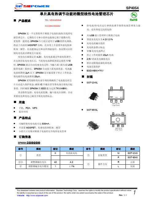
■ 功能框图
SP4054
■ 电学特性参数
输入电压
参数
输入电流
输出控制电压
BAT端电流
涓流充电电流
标号 Vcc Icc Vfloat
Ibat
Itrikl
条件
Charge mode,Rprog=10K Standby mode Shutdown mode(Rprog not connected,Vcc<Vbat or Vcc<Vuv) 0℃<TA<85℃, IBAT = 40mA Rprog=10k,Current mode Rprog=2k,Current mode Standby mode,Vbat=4.2V Shutdown mode Battery reverse mode, VBAT=-4V Sleep mode,Vcc=0V Vbat<Vtrikl,Rprog=2k
■ 封装
SOT-23-5L
5
4
PROG
VCC
SOT-89-5L
CHRG GND BAT
12 3
SOT-23-5L (Top View)
5
4
PROG PROG
VCC
CHRG GND BAT
1 23 1 SOT-829-5L 3
(Top View)
SP4054 ①②③④⑤⑥
标号 ① ②③ ④
描述 类型
Rev. 1.1
涓流充电极限电压 涓流充电迟滞电压 电源低电闭锁阈值电压 电源低电阈值电压迟滞电压 手动关闭阈值电压
Vcc-Vbat停止工作阈值电压
C/10 终端阈值电流 PROG端电压 CHRG端弱下拉电流 CHRG端最小输出电压 电池再充电迟滞电压
258 Encoders 金属杆壳型绝对类型 EC18A 水抗性强、重力扭矩强 18mm 尺寸 金属

259EncodersMetal ShaftInsulatedShaftThroughShaft TypeRing TypeStandard Codes 1. The ●marks shows the ON position.2. The ●marks : Connections between terminals and the 5 (COM) are ON.Waterproof PropertyImmersion of encoder, not in operation, in water at depth of 1m at normal temperature for 30 minutes.EC18AGAPosition No.123456789101112Rotation angle (° )3060901201501802102402703003301●●●●●●2●●●●3●●●●●●4●●●●5(COM )●●●●●●●●●●●●T E R M I N A L N O .EC18AGB20401Position No.12345678910111213141516Rotation angle (° )22.54567.590112.5135157.5180202.5225247.5270292.5315337.51●●●●●●●●2●●●●●●●●3●●●●●●●●4●●●●●●●●5(COM )●●●●●●●●●●●●●●●●T E R M I N A L N O .EC18AGB20407Position No.123456789101112131415Rotation angle (° )244872961201441681922162402642883123361●●●●●●●●2●●●●●●●●3●●●●●●●●4●●●●●●●●5(COM )●●●●●●●●●●●●●●●T E R M I N A L N O .EC18A /18mm Size Insulated Shaft Type(Two phase A and B )275EncodersMetal ShaftInsulated Shaft Through Shaft TypeRing Type1. When using an infrared reflow oven, solder may sometimes not be applied. Be sure to use a hot air reflow oven or a type that uses infrared rays in combination with hot air.2. The temperatures given above are the maximum temperatures at the terminals of the encoder when employing a hot air reflow method. The temperature of the PC board and the surface temperature of the encoder may vary greatly depending on the PC board material, its size and thickness. Ensure that the surface temperature of the encoder does not rise to 250℃ or greater.3. Conditions vary to some extent depending on the type of reflow bath used. Be sure to give due consideration to this prior to use.NotesEC05E EC21CEC28C, EC35CH250℃ min.230℃ to 245℃260℃230℃ min.220℃ 230℃180℃200℃180℃150℃150℃150℃60s to 120s 60s to 120s 2 min. min.ーー3s30s to 40s 25s to 60s40sー300s max.230s max.2 times max.1 time max.1 time max.Soldering surfacetemperatureSoldering temperatureHeating timeSoldering timeNo. of soldersEC09E, EC111, EC11E, EC11M, EC11N, EC18A,EC21A, EC28A, EC35A, EC35AH, EC50A Series100℃ max.260±5℃2 min. max.5±1s 2 times max.PreheatingDip solderingReference for Dip SolderingExample of Reflow Soldering ConditionReference for Manual SolderingEC10E, EC12D, EC12E EM11BEC40A100℃ max.100℃ max.110℃ max.260±5℃260℃ max.260℃ max.1 min. max.1 min. max.1 min. max.3±1s 3s max.10s max.2 times max.2 times max.1 timeTemperature profile300200100A BC Time (s)G max.F max.H max.E max.RoomtemperatureT e m p e r a t u r e (˚C )Pre-heating DEncoders / Soldering ConditionsEC05E, EC09E, EC10E, EC111, EC11E, EC11M, EC11N, EC12D, EC12E, EC18A, EC21A, EC28A, EC35A, EC35AH, EC40A, EC50A, EM11B, EC21C, EC28C, EC35CHSeries350℃ max.3s max. 1 timeTip temperatureSoldering timeNo. of soldersSeries ABCDEFGHNo. of reflows。
Gemini LTE 4G MIMO 2x2 外部天线说明书
LMA100.A.BI.001SpecificationPart No. : LMA100.A.BI.001Product Name : Gemini LTE 4G MIMO 2x2 Antenna for Routers and Access PointsFeature : Best solution for 4G 2x2 Worldwide LTE MIMO applications Covers fallback 3G/2G frequencies too(HSPA/UMTS/WCDMA/GSM/GPRS)698-960MHz,1710-2170MHz,2490-2690MHzHigh Efficiency Indoor and Outdoor AntennaWaterproof IP65Wall Mount or Desktop MountDimension: 164mm*164mm*36.5mm2* Low Loss 1M CFD-200 Cables - SMA(M)RoHS compliant1.IntroductionThe Gemini LTE 4G MIMO 2X2 is a robust external antenna that is fully IP65 waterproof for use with all 4G/3G/2G MIMO cellular routers and Access points worldwide. It includes two embedded high efficiency LTE MIMO antennas. The antenna elements operate at all common and 4G LTE bands worldwide; 698-960MHz, 1710-2170MHz, 2490-2690MHz, which also include the 3G and 2G bands, meaning the antenna can also be used as fallback on 3G or 2G applications. High isolation and low ECC between the two embedded MIMO antennas prevents self-interference. Low loss cables are used to keep efficiency high over long cable lengths up to 5 meters.This unique antenna offers two methods for easy installation, both indoors and outdoors.A bracket on the back of the antenna enables easy wall installation, keeping your work area clean and spacious. The antenna can also be placed on a flat surface using the stand holder for easy and quick installation.Typical Applications:-HD Real-time Streaming Video over LTE-Intelligent Transport Systems-Internet of Things (IoT market)-Digital Signage-HD Broadcast Systems-Wireless 4G LTE MIMO M2M devices with legacy 3G FunctionalityCable length and connector types are customizable. Contact your regional Taoglas sales office for support.2.Specification Table4G/3G/2G MIMO1 AntennaFrequency (MHz)LTE700 GSM850 GSM900 DCS PCS UMTS1 LTE2600 698~824 824~894 880~960 1710~1880 1850~1990 1920~2170 2490~2690 Efficiency (%)MIMO1 0.3M 77.91 57.40 46.79 66.09 61.53 43.94 41.33 1M 74.40 54.82 44.68 60.27 56.20 40.36 37.70 2M 66.31 48.59 38.91 49.44 45.76 32.97 29.63 3M 61.89 45.06 36.11 43.76 40.32 28.84 25.17 5M 53.13 37.96 30.30 34.20 31.13 22.32 19.24MIMO2 0.3M 73.17 46.21 37.12 71.80 59.28 45.79 45.25 1M 69.88 44.13 35.45 65.48 54.17 42.14 41.27 2M 62.28 39.09 30.87 53.75 44.11 34.45 32.49 3M 58.12 36.23 28.63 47.54 38.89 30.14 27.63 5M 49.90 30.55 24.07 37.19 30.01 23.33 21.11 Average Gain (dBi)MIMO1 0.3M -1.12 -2.46 -3.32 -1.83 -2.20 -3.82 -3.92 1M -1.32 -2.66 -3.52 -2.23 -2.59 -4.18 -4.32 2M -1.82 -3.18 -4.12 -3.09 -3.48 -5.06 -5.36 3M -2.12 -3.51 -4.45 -3.62 -4.04 -5.64 -6.07 5M -2.79 -4.26 -5.20 -4.69 -5.16 -6.75 -7.23MIMO2 0.3M -1.42 -3.36 -4.35 -1.45 -2.37 -3.55 -3.48 1M -1.62 -3.56 -4.55 -1.85 -2.76 -3.91 -3.88 2M -2.12 -4.09 -5.15 -2.71 -3.65 -4.78 -4.92 3M -2.42 -4.42 -5.48 -3.24 -4.21 -5.37 -5.63 5M -3.08 -5.16 -6.23 -4.31 -5.33 -6.47 -6.80Peak Gain (dBi)MIMO1 0.3M 4.76 3.42 3.07 4.68 4.68 4.20 2.41 1M 4.56 3.22 2.87 4.28 4.28 3.80 2.01 2M 4.06 2.72 2.27 3.38 3.38 2.90 1.01 3M 3.76 2.42 1.97 2.88 2.88 2.30 0.31 5M 3.16 1.62 1.17 1.78 1.78 1.20 -0.89MIMO2 0.3M 4.62 2.94 2.89 5.04 5.12 5.08 2.20 1M 4.42 2.74 2.69 4.64 4.72 4.68 1.80 2M 3.92 2.24 2.09 3.74 3.82 3.78 0.80 3M 3.62 1.84 1.79 3.24 3.32 3.28 0.10 5M 3.02 1.14 1.09 2.14 3.32 2.08 -1.00Impedance 50 ΩPolarization VerticalMECHANICALCasing PC+ABSCoaxial Cable CFD-200Cable Length 1 Meter Standard, Fully CustomizableConnector SMA Male Standard, Fully CustomizableWaterproof IP65Weight 400 g (Antenna with 1 meter Cable and Stand)Dimension 164mm*164mm*36.5mmENVIRONMENTALOperation Temperature -40°C to 85°CStorage Temperature -40°C to 85°CHumidity Non-condensing 65°C 95% RHLTE BANDSBand Number LTE / LTE-Advanced / WCDMA / HSPA / HSPA+ / TD-SCDMAUplink Downlink MIMO 1 MIMO 21 UL: 1920 to 1980 DL: 2110 to 2170 ✓✓2 UL: 1850 to 1910 DL: 1930 to 1990 ✓✓3 UL: 1710 to 1785 DL: 1805 to 1880 ✓✓4 UL: 1710 to 1755 DL: 2110 to 2155 ✓✓5 UL: 824 to 849 DL: 869 to 894 ✓✓7 UL: 2500 to 2570 DL:2620 to 2690 ✓✓8 UL: 880 to 915 DL: 925 to 960 ✓✓9 UL: 1749.9 to 1784.9 DL: 1844.9 to 1879.9 ✓✓11 UL: 1427.9 to 1447.9 DL: 1475.9 to 1495.912 UL: 699 to 716 DL: 729 to 746 ✓✓13 UL: 777 to 787 DL: 746 to 756 ✓✓14 UL: 788 to 798 DL: 758 to 768 ✓✓17 UL: 704 to 716 DL: 734 to 746 (LTE only) ✓✓18 UL: 815 to 830 DL: 860 to 875 (LET only) ✓✓19 UL: 830 to 845 DL: 875 to 890 ✓✓20 UL: 832 to 862 DL: 791 to 821 ✓✓21 UL: 1447.9 to 1462.9 DL: 1495.9 to 1510.922 UL: 3410 to 3490 DL: 3510 to 359023 UL:2000 to 2020 DL: 2180 to 2200 (LTE only) ✓✓24 UL:1625.5 to 1660.5 DL: 1525 to 1559 (LTE only)25 UL: 1850 to 1915 DL: 1930 to 1995 ✓✓26 UL: 814 to 849 DL: 859 to 894 ✓✓27 UL: 807 to 824 DL: 852 to 869 (LTE only) ✓✓28 UL: 703 to 748 DL: 758 to 803 (LTE only) ✓✓29 UL: - DL: 717 to 728 (LTE only) ✓✓30 UL: 2305 to 2315 DL: 2350 to 2360 (LTE only) ✓✓31 UL: 452.5 to 457.5 DL: 462.5 to 467.5 (LTE only)32 UL: - DL: 1452 - 1496 35 1850 to 1910 ✓✓38 2570 to 2620 ✓✓39 1880 to 1920 ✓✓40 2300 to 2400 ✓✓41 2496 to 2690 ✓✓42 3400 to 360043 3600 to 3800*Covered bands represent an efficiency greater than 20%3.Antenna Characteristics 3.1.Return Loss3.2.Efficiency3.3.Average Gain 3.4.Peak Gain4.Radiation Patterns4.1.Test SetupYXZ4.2.LTE MIMO1 (2D Radiation Pattern)XY Plane XZ Plane YZ PlaneXY XY XY ZXZXZXZYZYZY704MHz 824MHz 960MHz 1710MHz 2170MHz 2600MHzXY Plane XZ Plane YZ PlaneXY XY XY ZXZXZXZYZYZY704MHz 824MHz 960MHz1710MHz 2170MHz2600MHz5.Mechanical Drawing6.Packaging7.Installation Instructions 7.1.Package Contents7.2.Desktop Stand Installation7.3.Wall Mount Installation8.Application NoteThe LMA.100 antenna performance with different cable lengths is shown below.8.1.Isolation (Insertion Loss)8.1.1.S218.2.Return Loss 8.2.1.MIMO18.2.2.MIMO28.3.Efficiency 8.3.1.MIMO18.3.2.MIMO28.4.Average Gain 8.4.1.MIMO18.4.2.MIMO28.5.Peak Gain 8.5.1.MIMO18.5.2.MIMO2T aoglas makes no warranties based on the accuracy or completeness of the contents of this document and reserves the right to make changes to specifications and product descriptions at any time without notice. T aoglas reserves all rights to this document and the information contained herein.Reproduction, use or disclosure to third parties without express permission is strictly prohibited. Copyright © T aoglas Ltd.LMA100.A.BI.001。
- 1、下载文档前请自行甄别文档内容的完整性,平台不提供额外的编辑、内容补充、找答案等附加服务。
- 2、"仅部分预览"的文档,不可在线预览部分如存在完整性等问题,可反馈申请退款(可完整预览的文档不适用该条件!)。
- 3、如文档侵犯您的权益,请联系客服反馈,我们会尽快为您处理(人工客服工作时间:9:00-18:30)。
C ≤0.33 µF: 15000 MΩ min. (20 ºC 100 Vdc 60 s) C>0.33 µF: 5000 MΩ x µF min. (20 ºC 500 Vdc 60 s)2000 MΩ min. (20 ºC 100 Vdc 60 s)MetallizedBox Style, Vac RatedInterference Suppression and Across-the-line Vac ApplicationsThe Type MEXY metallized polyester class X2 and Y2/X2 film capacitors are ideal for across-the-line and line-to-ground interference suppression circuit applications. This product features the self-healing capabilities associated with metallized polyester, compact design and flame retardant construction meets UL 94V0.SpecificationsDielectric Strength: Between terminals: 575 Vac, 1768 Vdc 60 s Between terminals: 1500 Vac, 2121 Vdc 60 s (0.001 to 0.0068 µF) Between terminals to enclosure: 2050 Vac 60 s Agency ApprovalsSRoHS CompliantVoltage Range: 275 Vac/250 Vac, 60 Hz Capacitance Range: 0.001 µF - 2.2 µF Capacitance Tolerance: ±10% Std. ±20% Optl. Operating Temperature Range: –40 °C to 100 °C Dissipation Factor: 1.0% max. (20 ºC, 1kHz) Insulation Resistance:Pulse Capability Body Length (L)Rated AC Voltage 15 mm 17.5 mm 25.5 mm 30.5 mm dV/dt - volts per microsecond, maximum 275/250118623329Agency Specification # Agency/CDEFile # Application Voltage Capacitance Range UL 1414 E171988 Across-the-line Capacitors250 Vac .001 to 1.0 µF ULAntenna-coupling and Line-bypass Capacitors 250 Vac .001 to 1.0 µF UL 1283 (4th Ed) E223166 Electromagnetic Interference (EMI) Filters250 Vac 1.2 to 2.2 µF CSA C22.2 No. 1-94 218093 Across-the-line Capacitors250 Vac .001 to 1.0 µF CSAAntenna-isolation and Line-by-pass Capacitors CSA C22.2 No.8-M1986 218095 Electromagnetic Interference (EMI) Filters250 Vac 1.2 to 2.2 µF VDEIEC60384-14, 199340004840Class Y2/X2 275 Vac 0.001 to 0.0068 µF EN132400Class X2275 Vac0.0082 to 2.2 µFRatings RoHS CompliantCap. (µF)CatalogPart NumberT±.020 (0.5)(inches) (mm)H±0.020 (0.5)(inches) (mm)L± .020 (0.5)(inches) (mm)S± .015 (0.4)(inches) (mm)d(inches) (mm) 275 Vac (IEC384 - 14) 250Vac (UL/CSA)0.0010 MEXY2A102K 0.197 (5.0) 0.453 (11.5) 0.591 (15.0) 0.492 (12.5) 0.024 (0.60) 0.0012 MEXY2A122K 0.197 (5.0) 0.453 (11.5) 0.591 (15.0) 0.492 (12.5) 0.024 (0.60) 0.0015 MEXY2A152K 0.197 (5.0) 0.453 (11.5) 0.591 (15.0) 0.492 (12.5) 0.024 (0.60) 0.0018 MEXY2A182K 0.197 (5.0) 0.453 (11.5) 0.591 (15.0) 0.492 (12.5) 0.024 (0.60) 0.0022 MEXY2A222K 0.197 (5.0) 0.453 (11.5) 0.591 (15.0) 0.492 (12.5) 0.024 (0.60) 0.0027 MEXY2A272K 0.197 (5.0) 0.453 (11.5) 0.591 (15.0) 0.492 (12.5) 0.024 (0.60) 0.0033 MEXY2A332K 0.197 (5.0) 0.453 (11.5) 0.591 (15.0) 0.492 (12.5) 0.024 (0.60) 0.0039 MEXY2A392K 0.197 (5.0) 0.453 (11.5) 0.591 (15.0) 0.492 (12.5) 0.024 (0.60) 0.0047 MEXY2A472K 0.197 (5.0) 0.453 (11.5) 0.591 (15.0) 0.492 (12.5) 0.024 (0.60) 0.0056 MEXY2A562K 0.197 (5.0) 0.453 (11.5) 0.591 (15.0) 0.492 (12.5) 0.024 (0.60) 0.0068 MEXY2A682K 0.197 (5.0) 0.453 (11.5) 0.591 (15.0) 0.492 (12.5) 0.024 (0.60) 0.0082 MEXY2A822K 0.197 (5.0) 0.453 (11.5) 0.591 (15.0) 0.492 (12.5) 0.024 (0.60) 0.010 MEXY2A103K 0.197 (5.0) 0.453 (11.5) 0.591 (15.0) 0.492 (12.5) 0.024 (0.60) 0.012 MEXY2A123K 0.197 (5.0) 0.453 (11.5) 0.591 (15.0) 0.492 (12.5) 0.024 (0.60) 0.015 MEXY2A153K 0.197 (5.0) 0.453 (11.5) 0.591 (15.0) 0.492 (12.5) 0.024 (0.60) 0.018 MEXY2A183K 0.197 (5.0) 0.453 (11.5) 0.591 (15.0) 0.492 (12.5) 0.024 (0.60) 0.022 MEXY2A223K 0.197 (5.0) 0.453 (11.5) 0.591 (15.0) 0.492 (12.5) 0.024 (0.60) 0.027 MEXY2A273K 0.197 (5.0) 0.453 (11.5) 0.591 (15.0) 0.492 (12.5) 0.024 (0.60) 0.033 MEXY2A333K 0.236 (6.0) 0.512 (13.0) 0.591 (15.0) 0.492 (12.5) 0.024 (0.60) 0.039 MEXY2A393K 0.236 (6.0) 0.512 (13.0) 0.591 (15.0) 0.492 (12.5) 0.024 (0.60) 0.047 MEXY2A473K 0.236 (6.0) 0.512 (13.0) 0.591 (15.0) 0.492 (12.5) 0.024 (0.60) 0.056 MEXY2A563K 0.177 (4.5) 0.453 (11.5) 0.689 (17.5) 0.591 (15.0) 0.024 (0.60) 0.068 MEXY2A683K 0.177 (4.5) 0.453 (11.5) 0.689 (17.5) 0.591 (15.0) 0.024 (0.60) 0.082 MEXY2A823K 0.217 (5.5) 0.472 (12.0) 0.689 (17.5) 0.591 (15.0) 0.024 (0.60) 0.100 MEXY2A104K 0.217 (5.5) 0.472 (12.0) 0.689 (17.5) 0.591 (15.0) 0.024 (0.60) 0.120 MEXY2A124K 0.256 (6.5) 0.571 (14.5) 0.689 (17.5) 0.591 (15.0) 0.024 (0.60) 0.150 MEXY2A154K 0.256 (6.5) 0.571 (14.5) 0.689 (17.5) 0.591 (15.0) 0.024 (0.60) 0.180 MEXY2A184K 0.315 (8.0) 0.630 (16.0) 0.689 (17.5) 0.591 (15.0) 0.024 (0.60) 0.220 MEXY2A224K 0.315 (8.0) 0.630 (16.0) 0.689 (17.5) 0.591 (15.0) 0.024 (0.60) 0.270 MEXY2A274K 0.374 (9.5) 0.693 (17.5) 0.689 (17.5) 0.591 (15.0) 0.031 (0.80) 0.330 MEXY2A334K 0.374 (9.5) 0.693 (17.5) 0.689 (17.5) 0.591 (15.0) 0.031 (0.80) 0.390 MEXY2A394K 0.335 (8.5) 0.693 (17.5) 1.004 (25.5) 0.886 (22.5) 0.031 (0.80) 0.470 MEXY2A474K 0.335 (8.5) 0.693 (17.5) 1.004 (25.5) 0.886 (22.5) 0.031 (0.80) 0.560 MEXY2A564K 0.413 (10.5) 0.768 (19.5) 1.004 (25.5) 0.886 (22.5) 0.031 (0.80) 0.680 MEXY2A684K 0.413 (10.5) 0.768 (19.5) 1.004 (25.5) 0.886 (22.5) 0.031 (0.80)0.820 MEXY2A824K 0.472 (12.0) 0.866 (22.0) 1.004 (25.5) 0.886 (22.5) 0.031 (0.80)1.000 MEXY2A105K 0.472 (12.0) 0.866 (22.0) 1.004 (25.5) 0.886 (22.5) 0.031 (0.80) 1.200 MEXY2A125K 0.650 (16.5) 1.024 (26.0) 1.201 (30.5) 1.083 (27.5) 0.031 (0.80) 1.500 MEXY2A155K 0.650 (16.5) 1.024 (26.0) 1.201 (30.5) 1.083 (27.5) 0.031 (0.80)1.800 MEXY2A185K 0.748 (19.0) 1.161 (29.5) 1.201 (30.5) 1.083 (27.5) 0.031 (0.80)2.200 MEXY2A225K 0.748 (19.0) 1.161 (29.5) 1.201 (30.5) 1.083 (27.5) 0.031 (0.80)。