N35S-333-AU0030-KI中文资料
晋口晖N-型单面模块产品说明书

N-TypeMONO-FACIAL MODULEPositive power tolerance of 0~+3%ISO9001:2015: Quality Management System ISO14001:2015: Environment Management System ISO45001:2018Occupational health and safety management systemsIEC61215(2016), IEC61730(2016)Key FeaturesSMBB TechnologyBetter light trapping and current collection to improve module power output and reliability.LINEAR PERFORMANCE WARRANTYTiger Neo N-type 78HL4-(V)595-615 WattCertified to withstand: wind load (2400 Pascal) and snow load (5400 Pascal).Enhanced Mechanical Load2400 Pa 5400 PaPID ResistanceExcellent Anti-PID performance guarantee via optimized mass-production process and materials control.2.0Hot 2.0 TechnologyThe N-type module with Hot 2.0 technology has better reliability and lower LID/LETID.HOT12Year Produ ct Warrant y 30Year Linea r Power Wa rranty0.40%Annual De gradation Over 30 ye ars99%100%11230yearsGuar an tee dP o w e r P e r f o r m a n c e87.4%High salt mist and ammonia resistance.Durability Against Extreme Environmental ConditionsIrradiance 1000W/m2AM=1.5Irradiance 800W/m 2AM=1.5NOCT:*STC:Wind Speed 1m/sModule TypeMaximum Power (Pmax) Maximum Power Voltage (Vmp) Maximum Power Current (Imp) Open-circuit Voltage (Voc)Short-circuit Current (Isc)Module Efficiency STC (%)Operating Temperature(℃) Maximum system voltage Maximum series fuse rating Power toleranceTemperature coefficients of Pmax Temperature coefficients of Voc Temperature coefficients of IscNominal operating cell temperature (NOCT)Cell Temperature 25°CAmbient Temperature 20°C( Two pallets = One stack )31pcs/pallets, 62pcs/stack, 496pcs/ 40'HQ ContainerTemperature Dependence ofIsc,Voc,PmaxCurrent-Voltage & Power-VoltageCurves (605W)NOCT STCNOCT STC NOCT STC JKM595N-78HL4JKM595N-78HL4-V JKM600N-78HL4JKM600N-78HL4-V JKM605N-78HL4JKM605N-78HL4-V JKM610N-78HL4JKM610N-78HL4-V JKM615N-78HL4JKM615N-78HL4-V JKM595-615N-78HL4-(V)-F1-EN (IEC 2016)©2021 Jinko Solar Co., Ltd. All rights reserved.Specifications included in this datasheet are subject to change without notice.-40℃~+85℃1000/1500VDC (IEC)30A 0~+3%-0.30%/℃-0.25%/℃0.046%/℃45±2℃C u r r e n t (A )Voltage (V)Cell Temperature (℃)P o w e r (W )N o r m a l i z e d I s c , V o c , P m a x (%)NOCT STC NOCT STC 0246810120701402103502804204905606301416051015202530354045505560Length: ±2mmWidth: ±2mmHeight: ±1mm Row Pitch: ±2mm00ⅠⅡFrontSideBackB-BA-A Cell Type No. of cells Dimensions WeightFront Glass Frame Junction Box Output Cables30.6 kg (67.46 lbs)IP68 RatedTUV 1×4.0mm(+): 400mm , (-): 200mm or Customized Length3.2mm,Anti-Reflection Coating,High Transmission, Low Iron, Tempered GlassAnodized Aluminium Alloy2465×1134×35mm (97.05×44.65×1.38 inch)156 (2×78)N type Mono-crystalline000000-50-25025507510020406080100120140160180IscVocPmax21.29%595Wp 45.29V 13.14A 54.80V 13.90A447Wp 10.67A 41.93V 52.05V 11.22A21.46%600Wp 45.39V 13.22A 54.95V 13.97A451Wp 10.73A 42.05V 52.20V 11.28A21.64%605Wp 45.49V 13.30A 55.10V 14.04A455Wp 10.79A 42.16V 52.34V 11.34A21.82%610Wp 45.59V 13.38A 55.25V 14.11A459Wp 10.85A 42.28V 52.48V 11.39A22.00%615Wp 45.69V 13.46A 55.40V 14.18A462Wp 10.91A 42.39V 52.62V 11.45A。
美国力特保护继电器 SE
]
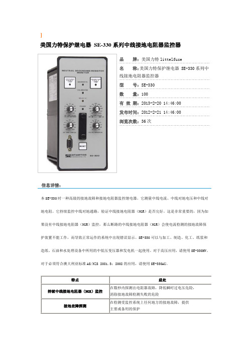
美国力特保护继电器SE-330系列中线接地电阻器监控器
品牌:美国力特littelfuse
名称:美国力特保护继电器 SE-330系列中
线接地电阻器监控器
型号:SE-330
数量:100
有效期:2013-2-20 14:46:00
发布时间:2012-2-21 14:46:00
浏览次数:36次
信息详情:
本SE-330时一种高级的接地故障和接地电阻器监控继电器。
它测量中线电流、中线对地电压和中线对地电阻。
它持续监控中线对地通路,验证中线接地电阻器(NGR)是否完好。
这是非常重要的,因为如果没有中线接地电阻器(NGR)监控,那么断路的中线接地电阻器(NGR)会使电流检测的接地故障保护装置不能工作,而导致正常运作的系统中出现错误显示。
SE-330可以与加工、制造、化工、纸浆和造纸、石油和水处理设备中所用的中低压变压器和发电机一起使用。
对于高压应用,请使用SE-330HV。
对于必须符合澳大利亚标准AS/NZS 2081.3:2002的应用,请使用SE-330AU。
规格:。
IJSR-4000 JM03G technical data sheet说明书

Head office:900 Hirasawa,Ranzan-machi,Hiki-gun,Saitama,355-0215 JapanMarketing office:TEL:+81-493-61-2832FAX:81-493-61-2833T echnical Development Div:TEL:+81-493-61-2728FAX:+81-493-61-2729UV / Thermal curable (One component) solder resist inkIJSR-4000 JM03GUL Suffix: IJSR-4000AA (File #E69262)1.FEATURESIJSR-4000 JM03G is inkjetable solder resist ink with the following features.Excellent adhesion to laminate with dual cure (UV + Thermal) processTack free right after printing due to On-head UV lamp on inkjet head, which provides excellent processability3.VISCOSITY CURVE4.PRINTING PARAMETERSThis parameter is guide for starting printing test. We recommend to evaluate optimal printing parameter for your equipment by use of this guide, because the optimal5.STANDARD CURING CONDITIONIJSR-4000 JM03G is cured by below steps.5-1. UV pre-curing ⇒5-2. Thermal curing ⇒ 5-3. UV bump*Measured by UV Power Puck II5-2. Thermal curing150deg.C 60min @box oven *Measured by UV Power Puck II*Measured by UV Power Puck II7.ATTENTION ON EACH PROCESSFor operation environment, desirable to handle the ink under the yellow lamps in the clean room of temp. range 20-25deg.C and 50-60%RH.Make ink temperature reach to room temperature, and stir sufficiently before use. UV curing conditions depend on the type of UV lamp. Inappropriate UV lamp may cause insufficient curability.Note: The test result is under above-referenced process conditions and test methods.Moreover, content in this technical data sheet is based on our internal experiment, not to be guaranteed. Therefore, please check the required property in advance of use.9. ATTENTIONCaution and care is required for handling. For the detail, refer to SDS.No intentional usage of restricted substances in EU RoHS to this product and its production process; Namely Cadmium, Lead, Mercury, Hexavalent Chromium, PBB and PBDE.。
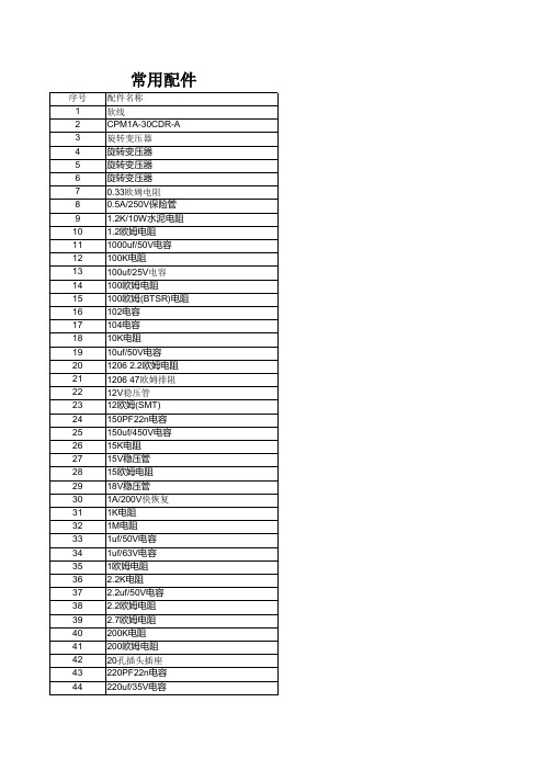
常用配件
233 234 235 236 237 238 239 240 241 242 243 244 245 246 247 248 249 250 251 252 253 254 255 256 257 258 259 260 261 262 263 264 265 266 267 268 269 270 271 272 273 274 275 276 277 278 279
327 328 329 330 331 332 333 334 335 336 337 338 339 340 341 342 343 344 345 346 347 348 349 350 351 352 353 354 355 356 357 358 359 360 361 362 363 364 365 366 367 368 369 370 371 372 373
M29F400BT PCB2832直流接触器 GAL22V10-10 AMP单15PIN插双30PIN插头 AMP单4PIN插双8PIN插头 变频器大插头 风门马达用白色插头 AMP2PIN插头 3A保险管 SK1848 35V/10uf电容(贴片) 乐泰胶水326 30W烙铁内芯 30W烙铁头 USB延长线 断纱感应器控制板 5W/10欧姆(水泥电阻) 74HC08D 焊台手柄 6305轴承 50V/4.7nf电容 MTD2003B LM2672 VIPER12A ESM6045DC L298N L9823 L6598 P12NM50 DG419 LM2576T-ADJ MBR1045T 万能板 250V/2200uf电容 74HC86 50V/22uf插脚电容 G2R-1 12VDC 塑料螺丝 STPS1045D 2A/250V保险 3.15A/250V保险 500欧姆可调电阻 FDU-3插头 BACK MAGENT(A1N1SA268) FRONT MAGENT(A1N1SA208) 变压器 6003轴承
3003新一代推车专业级(LED)说明书

引言尊敬的用户:欢迎使用SW-3000系列红外乳腺检查仪。
“三维”红外乳腺检查仪能得到您的信任,我们深表荣幸。
本说明书的用途在于帮助您正确地使用本产品,内容包括概述、结构特征及工作原理、技术特性、安装说明、使用说明、注意事项、故障分析与排除、保养及维护、售后服务等。
在安装和使用本产品之前,请您务必先仔细阅读随机配送的所有资料,特别是本说明书中安全信息及其他条款所提及的注意事项。
这会有助于您更好地使用本产品。
另外,在使用过程中,如果您有什么问题,请来电、来函查询,或登陆三维网站,我们定当竭诚为您服务。
品牌电脑,打印机等享受全国联保的部分请咨询其免费服务电话,以获得高品质的维护。
免责声明本说明书的描述不代表对本产品规格和软、硬件配置的任何说明。
有关产品规格和配置情况,请查阅本产品的相关协议、装箱单或向产品销售商咨询。
在本说明书编制过程中,已力求内容的正确和完整,但不能保证本手册没有任何错误和疏漏。
徐州市三维医疗设备有限公司坚持不断优化、改善自己的产品和服务,为此保留对本说明书描述的产品及本说明书的内容随时进行修改的权利,恕不另行通知。
如您在使用本说明书过程中发现本产品的实际情况与本说明书有不一致之处,如您想得到最新的信息或有任何问题和想法,欢迎致电我们或登陆三维网站垂询。
有限保证/保修本产品附带了标准服务承诺(保修内容),我们将按照该保修内容为您提供售后服务。
超出本标准的服务承诺,三维公司不提供服务,您应要求向您提供本产品的机构或人员按其承诺为您提供售后服务支持。
在法律允许的最大限度内,在任何情况下徐州市三维医疗设备有限公司无须对下列任何一项负责:1、第三方对您的索赔要求(人身死亡、伤害,不动产和相关有形财产的损害赔偿除外);2、您的记录或数据的丢失或损坏;3、特别的、附带的或间接的损害或任何后果性的经济损失(包括利润和储蓄金的损失),即使徐州市三维医疗设备有限公司已被告知发生上述损失的可能性时,也是如此;4、由于您安装非随本产品提供的软件或硬件产品引起的故障,经判定不是三维产品本身的问题;5、由于您未在本说明书所规定的环境使用本产品,或未按使用说明书所规定的操作方法引起的故障;6、不可抗力因素导致产品损坏的情况。
欧姆尼克 3R3 电感说明书

Dimensions: [mm]Scale - 7:1Product Marking:Marking3R3 (Inductance Code)7440404103374404041033BC74404041033T e m p e r a t u r eT pT L74404041033Cautions and Warnings:The following conditions apply to all goods within the product series of WE-LQS of Würth Elektronik eiSos GmbH & Co. KG:General:•This electronic component is designed and manufactured for use in general electronic equipment.•Würth Elektronik must be asked for written approval (following the PPAP procedure) before incorporating the components into any equipment in fields such as military, aerospace, aviation, nuclear control, submarine, transportation (automotive control, train control, ship control), transportation signal, disaster prevention, medical, public information network etc. where higher safety and reliability are especially required and/or if there is the possibility of direct damage or human injury.•Electronic components that will be used in safety-critical or high-reliability applications, should be pre-evaluated by the customer. •The component is designed and manufactured to be used within the datasheet specified values. If the usage and operation conditions specified in the datasheet are not met, the wire insulation may be damaged or dissolved.•Do not drop or impact the components, the component may be damaged.•Würth Elektronik products are qualified according to international standards, which are listed in each product reliability report. Würth Elektronik does not warrant any customer qualified product characteristics beyond Würth Elektroniks’ specifications, for its validity and sustainability over time.•The responsibility for the applicability of the customer specific products and use in a particular customer design is always within the authority of the customer. All technical specifications for standard products also apply to customer specific products.Product specific:Soldering:•The solder profile must comply with the technical product specifications. All other profiles will void the warranty.•All other soldering methods are at the customers’ own risk.•Strong forces which may affect the coplanarity of the components’ electrical connection with the PCB (i.e. pins), can damage the part, resulting in avoid of the warranty.Cleaning and Washing:•Washing agents used during the production to clean the customer application might damage or change the characteristics of the wire insulation, marking or plating. Washing agents may have a negative effect on the long-term functionality of the product.•Using a brush during the cleaning process may break the wire due to its small diameter. Therefore, we do not recommend using a brush during the PCB cleaning process.Potting:•If the product is potted in the customer application, the potting material may shrink or expand during and after hardening. Shrinking could lead to an incomplete seal, allowing contaminants into the core. Expansion could damage the components. We recommend a manual inspection after potting to avoid these effects.Storage Conditions:• A storage of Würth Elektronik products for longer than 12 months is not recommended. Within other effects, the terminals may suffer degradation, resulting in bad solderability. Therefore, all products shall be used within the period of 12 months based on the day of shipment.•Do not expose the components to direct sunlight.•The storage conditions in the original packaging are defined according to DIN EN 61760-2.•The storage conditions stated in the original packaging apply to the storage time and not to the transportation time of the components. Packaging:•The packaging specifications apply only to purchase orders comprising whole packaging units. If the ordered quantity exceeds or is lower than the specified packaging unit, packaging in accordance with the packaging specifications cannot be ensured. Handling:•Violation of the technical product specifications such as exceeding the nominal rated current will void the warranty.•Applying currents with audio-frequency signals may result in audible noise due to the magnetostrictive material properties.•The temperature rise of the component must be taken into consideration. The operating temperature is comprised of ambient temperature and temperature rise of the component.The operating temperature of the component shall not exceed the maximum temperature specified.These cautions and warnings comply with the state of the scientific and technical knowledge and are believed to be accurate and reliable.However, no responsibility is assumed for inaccuracies or incompleteness.Würth Elektronik eiSos GmbH & Co. KGEMC & Inductive SolutionsMax-Eyth-Str. 174638 WaldenburgGermanyCHECKED REVISION DATE (YYYY-MM-DD)GENERAL TOLERANCE PROJECTIONMETHODChriB002.0012023-02-28DIN ISO 2768-1mDESCRIPTIONWE-LQS SMT Semi-ShieldedPower Inductor ORDER CODE74404041033SIZE/TYPE BUSINESS UNIT STATUS PAGEImportant NotesThe following conditions apply to all goods within the product range of Würth Elektronik eiSos GmbH & Co. KG:1. General Customer ResponsibilitySome goods within the product range of Würth Elektronik eiSos GmbH & Co. KG contain statements regarding general suitability for certain application areas. These statements about suitability are based on our knowledge and experience of typical requirements concerning the areas, serve as general guidance and cannot be estimated as binding statements about the suitability for a customer application. The responsibility for the applicability and use in a particular customer design is always solely within the authority of the customer. Due to this fact it is up to the customer to evaluate, where appropriate to investigate and decide whether the device with the specific product characteristics described in the product specification is valid and suitable for the respective customer application or not.2. Customer Responsibility related to Specific, in particular Safety-Relevant ApplicationsIt has to be clearly pointed out that the possibility of a malfunction of electronic components or failure before the end of the usual lifetime cannot be completely eliminated in the current state of the art, even if the products are operated within the range of the specifications.In certain customer applications requiring a very high level of safety and especially in customer applications in which the malfunction or failure of an electronic component could endanger human life or health it must be ensured by most advanced technological aid of suitable design of the customer application that no injury or damage is caused to third parties in the event of malfunction or failure of an electronic component. Therefore, customer is cautioned to verify that data sheets are current before placing orders. The current data sheets can be downloaded at .3. Best Care and AttentionAny product-specific notes, cautions and warnings must be strictly observed. Any disregard will result in the loss of warranty.4. Customer Support for Product SpecificationsSome products within the product range may contain substances which are subject to restrictions in certain jurisdictions in order to serve specific technical requirements. Necessary information is available on request. In this case the field sales engineer or the internal sales person in charge should be contacted who will be happy to support in this matter.5. Product R&DDue to constant product improvement product specifications may change from time to time. As a standard reporting procedure of the Product Change Notification (PCN) according to the JEDEC-Standard inform about minor and major changes. In case of further queries regarding the PCN, the field sales engineer or the internal sales person in charge should be contacted. The basic responsibility of the customer as per Section 1 and 2 remains unaffected.6. Product Life CycleDue to technical progress and economical evaluation we also reserve the right to discontinue production and delivery of products. As a standard reporting procedure of the Product Termination Notification (PTN) according to the JEDEC-Standard we will inform at an early stage about inevitable product discontinuance. According to this we cannot guarantee that all products within our product range will always be available. Therefore it needs to be verified with the field sales engineer or the internal sales person in charge about the current product availability expectancy before or when the product for application design-in disposal is considered. The approach named above does not apply in the case of individual agreements deviating from the foregoing for customer-specific products.7. Property RightsAll the rights for contractual products produced by Würth Elektronik eiSos GmbH & Co. KG on the basis of ideas, development contracts as well as models or templates that are subject to copyright, patent or commercial protection supplied to the customer will remain with Würth Elektronik eiSos GmbH & Co. KG. Würth Elektronik eiSos GmbH & Co. KG does not warrant or represent that any license, either expressed or implied, is granted under any patent right, copyright, mask work right, or other intellectual property right relating to any combination, application, or process in which Würth Elektronik eiSos GmbH & Co. KG components or services are used.8. General Terms and ConditionsUnless otherwise agreed in individual contracts, all orders are subject to the current version of the “General Terms and Conditions of Würth Elektronik eiSos Group”, last version available at .Würth Elektronik eiSos GmbH & Co. KGEMC & Inductive SolutionsMax-Eyth-Str. 174638 WaldenburgGermanyCHECKED REVISION DATE (YYYY-MM-DD)GENERAL TOLERANCE PROJECTIONMETHODChriB002.0012023-02-28DIN ISO 2768-1mDESCRIPTIONWE-LQS SMT Semi-ShieldedPower Inductor ORDER CODE74404041033SIZE/TYPE BUSINESS UNIT STATUS PAGE。
REF3333中文资料

BurrĆBrown Products from Texas Instruments
REF3312, REF3318 REF3320, REF3325 REF3330, REF3333
SBOS392A – AUGUST 2007 – REVISED SEPTEMBER 2007
NOISE Output Voltage Noise
OUTPUT VOLTAGE Initial Accuracy
NOISE OutputБайду номын сангаасVoltage Noise
OUTPUT VOLTAGE Initial Accuracy
NOISE Output Voltage Noise
OUTPUT VOLTAGE Initial Accuracy
Boldface limits apply over the specified temperature range, –40°C to +125°C. At TA = +25°C and ILOAD = 0mA, unless otherwise noted.
PARAMETER
OUTPUT VOLTAGE Initial Accuracy
MAX +0.15 +0.15 +0.15 +0.15 +0.15 +0.15
UNITS
V % μVPP
V % μVPP
V % μVPP
V % μVPP
V % μVPP
V % μVPP
Copyright © 2007, Texas Instruments Incorporated
f = 0.1Hz to 10Hz REF3330 (3.0V) VIN = 5V
3680系列精密潜入杆电阻器产品说明书
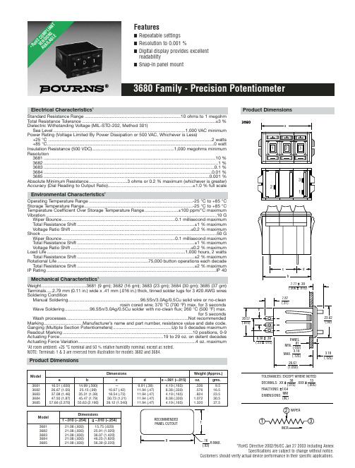
*RoHS Directive 2002/95/EC Jan 27 2003 including AnnexSpecifications are subject to change without notice.Customers should verify actual device performance in their specific applications.Electrical Characteristics 1Standard Resistance Range .............................................................................10 ohms to 1 megohm Total Resistance Tolerance...........................................................................................................±3 %Dielectric Withstanding Voltage (MIL-STD-202, Method 301)Sea Level..........................................................................................................1,000 VAC minimum Power Rating (Voltage Limited By Power Dissipation or 500 VAC, Whichever is Less)+25 °C ...................................................................................................................................2 watts +85 °C......................................................................................................................................0 watt Insulation Resistance (500 VDC)..................................................................1,000 megohms minimum Resolution3681..........................................................................................................................................10 %3682............................................................................................................................................1 %3683.........................................................................................................................................0.1 %3684.......................................................................................................................................0.01 %3685.....................................................................................................................................0.001 %Absolute Minimum Resistance...............................3 ohms or 0.2 % maximum (whichever is greater)Accuracy (Dial Reading to Output Ratio)....................................................................±1.0 % full scaleEnvironmental Characteristics1Operating Temperature Range ...................................................................................-25 °C to +85 °C Storage Temperature Range.......................................................................................-25 °C to +85 °C Temperature Coefficient Over Storage Temperature Range...........................±100 ppm/°C maximum Vibration.........................................................................................................................................10 G Wiper Bounce...........................................................................................0.1 millisecond maximum Total Resistance Shift..............................................................................................±1 % maximum Voltage Ratio Shift................................................................................................±0.2 % maximum Shock.............................................................................................................................................50 G Wiper Bounce...........................................................................................0.1 millisecond maximum Total Resistance Shift..............................................................................................±1 % maximum Voltage Ratio Shift................................................................................................±0.2 % maximum Load Life...............................................................................................................1,000 hours, 2 watts Total Resistance Shift..............................................................................................±2 % maximum Rotational Life.........................................................................75,000 button operations each decade Total Resistance Shift..............................................................................................±2 % maximum IP Rating........................................................................................................................................IP 40Mechanical Characteristics 1Weight....................................3681 (9 gm); 3682 (16 gm); 3683 (23 gm); 3684 (30 gm); 3685 (37 gm)T erminals.....2.79 mm (0.11 in.) wide x .41 mm (.016 in.) thick, tinned solder lugs for 3 #20 AWG wires Soldering ConditionManual Soldering..........................................................96.5Sn/3.0Ag/0.5Cu solid wire or no-cleanrosin cored wire; 370 °C (700 °F) max. for 3 secondsWave Soldering....................96.5Sn/3.0Ag/0.5Cu solder with no-clean flux; 260 °C (500 °F) max.for 5 secondsWash processes..................................................................................................Not recommended Marking...............................Manufacturer’s name and part number, resistance value and date code.Ganging (Multiple Section Potentiometers)...............................................Up to 5 decades maximum Readout Marking........................................................................................................10 positions, 0-9Actuating Force...................................................................................19 to 29 oz. on detent decades Actuating Force Variation..............................................................................................4 oz. maximum1At room ambient: +25 °C nominal and 50 % relative humidity nominal, except as noted.NOTE: Terminals 1 & 3 are reversed from illustration for models 3682 and 3684.3680INCR.Product DimensionsDimensionsWeight (Approx.)Model a b c d e –.381 (–.015)oz.gms.368116.51 (.650)14.99 (.590)—9.91 (.39) 4.19 (.165).3369.5368226.67 (1.05)25.15 (.99)10.67 (.42)11.94 (.47)8.38 (.330).57616.5368337.08 (1.46)35.31 (1.39)18.54 (.73)11.94 (.47) 4.19 (.165).82423.5368447.50 (1.87)45.47 (1.79)30.73 (1.21)11.94 (.47)8.38 (.330) 1.07230.5368557.66 (2.270)55.63 (2.190)39.12 (1.540)11.94 (.47)4.19 (.165)1.32037.5DimensionsModel f –.010 (–.254)g –.010 (–.254)368121.08 (.830)15.75 (.620)368221.08 (.830)25.91 (1.020)368321.08 (.830)36.07 (1.420)368421.08 (.830)46.23 (1.820)368521.08 (.830)56.39 (2.220)*Ro H S C O M P L I A N T V E R S I O N S A V A I L A B L ESpecifications are subject to change without notice.Customers should verify actual device performance in their specific applications.Recommended Part NumbersBOLDFACE LISTINGS ARE IN STOCK AND READILY AVAILABLE THROUGH DISTRIBUTION.FOR OTHER OPTIONS CONSULT FACTORY.RoHS IDENTIFIER:L =COMPLIANTBLANK =NON-COMPLIANTREV. 05/07。
- 1、下载文档前请自行甄别文档内容的完整性,平台不提供额外的编辑、内容补充、找答案等附加服务。
- 2、"仅部分预览"的文档,不可在线预览部分如存在完整性等问题,可反馈申请退款(可完整预览的文档不适用该条件!)。
- 3、如文档侵犯您的权益,请联系客服反馈,我们会尽快为您处理(人工客服工作时间:9:00-18:30)。
Channel Types Q=Quadrature Outputs P=1st Output CW Pulses 2nd Output CCW Pulses U=1st Output Pulse Train 2nd Output Logic High For CW Rotation, Low For CCW Rotation I=Index Pulse
* C is standard; for outputs “KI” or “LI” (line driver with index), index pin is E
For the latest specifications visit our website
Channel Types “P” “U” & “Q” 0025 0030 0050 0060 0075 0090 0093 0096 0120 0125 0128 0135 0180 0186 0192 0200 0250 0256 0270 0300 0400 0480 0500 0372 0540 0600 0720 0840 1024 1000 If “P” or “U” add (Square Wave) 0800 1080 1200 1440 1680 1920 2000 2048 If “P” or “U” add (Pulsed) 0768 1488 1600 2160 4000 3840 3360 2880
元器件交易网
Hercules Encoders
Specifications
Mechanical
Shaft Speed Shaft Direction Standard Shaft Sizes Shaft Extension(s) Shaft Seals Mounting Bearings Radial Loading Axial Loading Accuracy Housing Weight (N35) Connector 6000 RPM maximum Bidirectional .3747'', .4997" Std 0.875", .50 x .05" flat Neoprene or PTFE Options Refer to dimensional drawings ABEC 5 Spindle 90 lbs. Operating 45 lbs. Operating +0.1º of Shaft Rotation Typical Black Anodized Aluminum 36 oz. 6, 7, 10 Pin MS3102E or 18" Cable Out
N35T
—
335
—
K Q 1000
—
KI
Index Channel (same types as Channel Outputs)
Connector Style 1=6 Pin rear mounted 2= 6 Pin side mounted 3= 7 Pin rear mounted 4= 7 Pin side mounted 5=10 Pin rear mounted 6=10 Pin side mounted 7=Cable rear mounted 8=Cable side mounted
Consult factory for PPR not listed
0064 0100 0150 0240 0360 0512 0960
2400 4096
Output Ratings Open Collector Transistor Line Drivers 8-15 Vdc 5 Vdc TTL Supply VoltageBiblioteka Environmental
Operating Temp. Shock Vibration Humidity Enclosures (Sealed) -40º to +85º C (-40º to +185º F) 50 g’s for 11 Milliseconds 5 to 2000 Hertz at 20 g’s 100% Relative Humidity NEMA 4X equiv. — Water-tight
Channel Outputs (All outputs available with complementary outputs) A=NPN w/Pullup Res. B=NPN Open Collector F=5Vdc w/Pullup Res. G=5Vdc Open Collector H=PNP Sourcing Output K=5Vdc Line Driver L=8 to 15 Vdc Line Driver
40 Vdc maximum 15 Vdc maximum 5.5 Vdc maximum 8 to 28 Vdc 5 Vdc TTL output Supply Current, per channel 30 mA typical, 50 mA maximum Current Sinking 250 mA maximum Output Duty Cycle 50/50 w/ +20% typical tolerance Tighter to +5% by spec Pulsed Outputs 5-10 µsec or 25-35 µsec Rise/Fall Times 1 µsec typical, other options available See Wiring Diagrams for Pin Outs
元器件交易网
Dimensional Drawings
Series N35 Standard
Wire Drawings
Ordering Information
Size N35S=Sealed (Elastomer) N35T=Sealed (PTFE) Mounting Style 1=Flush mount 2=Servo mount 3=Flange mount Shaft Style 3=3/8" Standard Shaft 4=1/2" Standard Shaft
Series N35
Heavy Duty Incremental Rotary Shaft Encoder
• Enclosure: N35-3.5'' Dia. NEMA 4 type Sealing Servo, Flush or Flanged Mounting • Vibration-resistant Anti-Jitter Circuitry, Shatterproof Metal Code Discs • Shielded ABEC 5 Stainless Steel Spindle Bearings, Standard and Self-Mounting options • Low Supply Current Requirement - 30 milliamps typical per encoder, maximum of 50 mA • Operating Voltage Flexibility - 8 to 28 Vdc or 5 Vdc TTL Output, 5V or 8 - 15V with Line Driver • Operating Temperature Rating designed for extremes, from -40º to +85º C (-40º to +185º F)
Electrical Connections
Function +V Common Channel A Channel B Channel A Channel B Index Index 6 Pin B A D E C F C or E* F 7 Pin D F A B E G C G 10 Pin D F A B H I C J Cable Out D F A B E G C G Color Red Black Blue Brown White Green White Green
Electrical
Pulse Rate Outputs 15 kHz typical, up to 200 kHz available NPN w/ 3.3K pullup or open collector PNP sourcing Line Driver (with complementary outputs)