基于LABVIEW车牌识别停车系统设计共27页
基于车牌识别技术的自动安全车库系统设计(IJISA-V6-N2-3)
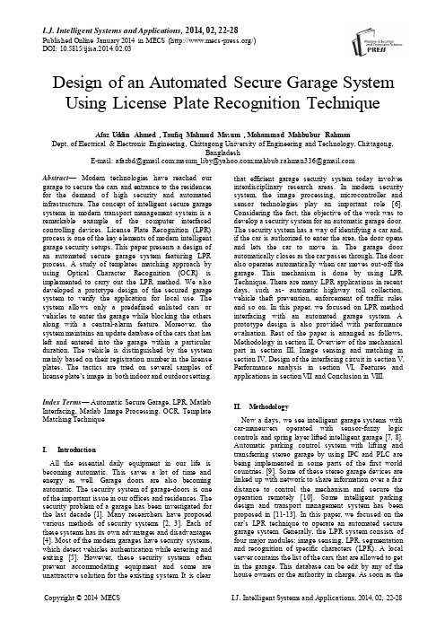
I.J. Intelligent Systems and Applications, 2014, 02, 22-28Published Online January 2014 in MECS (/)DOI: 10.5815/ijisa.2014.02.03Design of an Automated Secure Garage System Using License Plate Recognition Technique Afaz Uddin Ahmed , Taufiq Mahmud Masum , Mohammad Mahbubur Rahman Dept. of Electrical & Electronic Engineering, Chittagong University of Engineering and Technology, Chittagong,BangladeshE-mail: afazbd@;masum_liby@;mahbub.rahman336@Abstract—Modern technologies have reached our garage to secure the cars and entrance to the residences for the demand of high security and automated infrastructure. The concept of intelligent secure garage systems in modern transport management system is a remarkable example of the computer interfaced controlling devices. License Plate Recognition (LPR) process is one of the key elements of modern intelligent garage security setups. This paper presents a design of an automated secure garage system featuring LPR process. A study of templates matching approach by using Optical Character Recognition (OCR) is implemented to carry out the LPR method. We also developed a prototype design of the secured garage system to verify the application for local use. The system allows only a predefined enlisted cars or vehicles to enter the garage while blocking the others along with a central-alarm feature. Moreover, the system maintains an update database of the cars that has left and entered into the garage within a particular duration. The vehicle is distinguished by the system mainly based on their registration number in the license plates. The tactics are tried on several samples of license plate’s image in both indoor and outdoor setting. Index Terms— Automatic Secure Garage, LPR, Matlab Interfacing, Matlab Image Processing, OCR, Template Matching TechniqueI.IntroductionAll the essential daily equipment in our life is becoming automatic. This saves a lot of time and energy as well. Garage doors are also becoming automatic. The security system of garage-doors is one of the important issue in our offices and residences. The security problem of a garage has been investigated for the last decade [1]. Many researchers have proposed various methods of security systems [2, 3]. Each of these systems has its own advantages and disadvantages [4]. Most of the modern garages have security systems, which detect vehicles authentication while entering and exiting [5]. However, these security systems often prevent accommodating equipment and some are unattractive solution for the existing system. It is clear that efficient garage security system today involves interdisciplinary research areas. In modern security system, the image processing, microcontroller and sensor technologies play an important role [6]. Considering the fact, the objective of the work was to develop a security system for an automatic garage door. The security system has a way of identifying a car and, if the car is authorized to enter the area, the door opens and lets the car to move in. The garage door automatically closes as the car passes through. The door also operates automatically when car moves out-off the garage. This mechanism is done by using LPR Technique. There are many LPR applications in recent days, such as- automatic highway toll collection, vehicle theft prevention, enforcement of traffic rules and so on. In this paper, we focused on LPR method interfacing with an automated garage system. A prototype design is also provided with performance evaluation. Rest of the paper is arranged as follows, Methodology in section II, Overview of the mechanical part in section III, Image sensing and matching in section IV, Design of the interfacing circuit in section V, Performance analysis in section VI, Features and applications in section VII and Conclusion in VIII.II.MethodologyNow a days, we see intelligent garage systems with car-maneuvers operated with sensor-fuzzy logic controls and spring layer lifted intelligent garage [7, 8]. Automatic parking control system with lifting and transferring stereo garage by using IPC and PLC are being implemented in some parts of the first world countries. [9]. Some of these stereo garage devices are linked up with network to share information over a fair distance to control the mechanism and secure the operation remotely [10]. Some intelligent parking design and transport management system has been proposed in [11-13]. In this paper, we focused on the car’s LPR technique to operate an automated secure garage system. Generally, the LPR system consists of four major modules: image sensing, LPR, segmentation and recognition of specific characters (LPR). A local server contains the list of the cars that are allowed to get in the garage. This database can be edit by any of the house owners or the authority in charge. As soon as thecar appears in the front gate, it will activate a sensor which will be liked with a central control system (here we used a pc with MATLAB). The system grabs a picture of the license plate and analyses the reference cars ’ license plate number. After a successful match, the garage opens automatically allowing the car to get in. While passing the garage, the car again activates a sensor that executes the closing process of the garage doors. The system informs the car owner about the entrance of the car in the garage. The same process repeats when the car wants to get out of the garage. The LPR process is done by gray-image templates matching using optical character recognition process (OCR). The interfacing with the automated garage system is done by simple control circuits with stepper motor that gives flexibility to rotate both ways by just changing thephases.Fig. 1: Systematically process of the systemStep1 The car approaches in front of the garage and the wheel touches a plate. In addition, a signal passes from the plate through the parallel port of a computer. Step2 Sensing this signal, MATLAB starts the camera and grabs a picture of the car’s license plate. The picture is then stored.Step3 The stored picture is then processed through Optical Character Recognition and then the number and letters are saved in a text document.Step4 Image form references are taken and then converted into text. Then the both texts are compared. If the image matches, it gives logic 1 to step 5.Step5 If step 4 gives logic 1, then the motor interfaced by PC rotates and the sliding and cross bar gates open.Step6 When the car passes the gate, it touches another plate twice (for the front wheel and the back wheel). This sends two simultaneous signals to the PC. Step7 Then the motor rotates back to close both the doors.III. Overview of the Mechanical PartThe mechanical part is a miniature of a gate that is shown in Fig. 2. This gate model is similar to the gate model that we proposed for practical application. The sturcture is made of wood to get the flexibility of shapes and modification in the workshop. The frame of the gate is constructed on a wooden driveway. The driveway has two sensors at two different places, one before approaching the gate and another just after the gate. As these plates act like weight sensors, springs are attached to the plates to ensure the proper operation of the circuit. The gate has two parts. One crossing bar which is in front of the gate a horizontally siding doors that are next to the crossing bar. With the crossing bar, there is a camera attached for the graphical input of the license plate. The sliding doors have rack attached with it on the top. This rack meshes with a pinion that i s coupled with two stepper motors. The crossing bar also has a motor coupled, which is used to move the crossing bar up and down. A box with wheels attached is used asa car.Fig. 2: Wooden model of the gate and the drivewayWhen a car approaches the first plate, it touches the weight sensor, which closes the input circuit and sends a signal to the computer. The computer turns on the camera and takes the photograph of the license plate of the car. The photo is then filtered and matched with the photos saved in the database (the data is sent electronically), if it matches with any of the cars number in the list, the arrangement of opening the gates executes. Frist the stepper motor for the bar is switched on with a particular number of rotations and the bar moves up. As soon as the moving bar stops, the gate motor gets the signal for opening. The two sliding door moves in the opposite direction making a route for the cars to pass through it. When the car crosses the sliding door, it again touches a weight sensor and closes the circuit (usually the last plate operates after twoconsecutive contacts because of the front tire and the back tire). Than all the gates close by rotating in the opposite direction and gets in the original position. IV.Image Sensing and MatchingThe image processing and gray level template matching part is the heart of this process. The image is first converted to gray level. Than it is converted to binary format to match with individual characters of the reference picture. Each character is compared with a set of templates that are stored as a reference model. After that the character is been recognized and stored in a text document. Here in this system we used English alphabets and numerical numbers: 36 templates (A-Z= 26, 0-9=10) [14]. Changing the set of references, we can change the language of the system. We can also use multiple languages by using more than one set of alphabets and numerical numbers.Following are the steps how actually the image sensing works-First, a library for templates is created. This library contains images of different characters in gray format that can appear on the license plate. This is done before any image capturing or processing is done [15].When an image of the license plate is taken, the image is into grayscale. The digital image is then converted to binary image. The white part corresponds to 1 and the black part to 0.The image contains two parts, one with vast black area and other with white numbers on the black background. The number part is separated and appeared in a black area with white background. The number part itself has parts equal to the number of characters. These characters in the license plate are compared with reference templates. The matched template indicates particular alphabets and numerical numbers and it is stored in a specific text document (Cars.txt). Now, as all the license plate nu mbers of the allowed cars, which are in the library folder, are checked one by one and matched them with the previous file (Cars.txt). If any of the name matches with the car.txt, the logic will show 1 and the gate will open systematically. Then email notification will be sent to the owners of the car to make inform about the cars status. If none of the reference files matches, the output will be a red light. These processes are done by MATLAB. We have also made a database record for the cars that goes in and gets out with in last 6 hours. We have used a computer with video input device (webcam) and MATLAB programming to detect the optical characters template matching technique. Template matching in digital image processing for recognizing characters is very effective method. It can be used to detect edges in images. Here we used Grey-level template matching.In matching process, the templates’ images are moved to all possible points/scale in the source image to compute the numerical indication on success rate of the template matching in that image. This matching is done in pixel-by-pixel.4.1Optical Character RecognitionThe aim of optical character recognition (OCR) is to identify optical patterns like numerical numbers or letters or symbols in any picture. There are several steps in OCR that includes segmentation, feature extraction, and classification. Each of these steps is a field unto itself [14]. Figure 3 shows different stages of thi sprocess.Fig. 3: Different stages of Optical Character RecognitionFig. 4: Comparison and storage of the converted binary image First, the desired image is converted into grayscale. Then it will be converted in threshold binary. The image will be then compared with a set of alphabet and number image that we stored as templates. The conversion and matching will make an output of successful matching in a text document. Fig. 4 shows the process of storing matched image into a text document.The algorithm that was followed during the process is briefly described below-4.2 The Classification ProcessClassification is common for any kind of classifier. There are two main steps in developing classifier training and testing. These steps can be split into more sub-steps [6, 16]. Fig. 5 shows the block diagram representation of the sub-steps of this classificationprocess.Fig. 5: The pattern classification process of OCR (Pre-processing)a) Training• Pre-processing – Processes the collected data so it is in a suitable form for later processes.• Feature abstraction – Minimizes the total amount of data by extracting related information, usually results in a vector of scalar values.• Model Estimation – for each class of the training data, the finite set of feature vectors needs to estimate as a model. b) Testing• Pre-processing – (same as above) • Feature extraction – (same as above)• Classification – Differentiate the feature vectors to several models and extract the highest possible match.These steps are performed in OCR [17].1. Binarization – It is converting an image of up to 256 gray levels to a black and white image.2. Morphological Operators – Removes holes and isolated specks from the characters.3. Segmentation – Confirms connectivity of outlines labels and separate. Using the bwlabel’ and ‘regionprops’ functions of MATLAB, it can done easily [16]. Segmentation is the most important stage of the pre-processing method. It assists the recognizer to extract features from individual character. In the case of handwritten text, which is more complex, it becomes more difficult as characters are tending to be linked to each other. The overall process of OCRin this project is shown in Figure 6.Fig. 6: Block diagram of the programV. Design of the Interfacing CircuitTo design the control setup, we used eight relays, two ULN2003 IC and a 12V power supply. The circuit is connected as shown in Fig.7 below. When a signal comes to first pin of the ULN2003, it amplifies the current and relay is switched on. As the relay is closed, the motor gets a pulse to rotate one-step of 1.8 degrees. The next comes to the second pin, and the second relay causes another step rotation. As the ULN pin keeps getting sequential signal, the motor keep rotating [18]. The number of signal required is set by the program and the motors are controlled. The same thing is done for other motors. We used three motors. Two for the sliding gates and one for the crossing bar.A unipolar stepper motor has two windings per phase, one for each direction of magnetic field. Since in this arrangement a magnetic pole can be reversed without switching the direction of current, the commutation circuit can be made very simple (eg. a single transistor) for each winding. Typically, given a phase, one end of each winding is made common: giving three leads per phase and six leads for a typical two phase motor. Often, these two-phase commons are internally joined, so the motor has only five leads.Phase shifting of the stepper motor:Fig. 7: Clockwise RotationFig. 8: Connection diagram of the motor with the interfacing circuitTable 1: Functional TableAfter the character recognition process, the text isstored. We do the same thing to all the reference imageplates one by one and store them in other textdocuments. When a car arrives at the garage gate, wecompare two texts, one stored immediately after the carhas approached and another, which was stored in thelibrary previously. Block diagram of this process isdepicted in Figure 9.After comparing the two texts in MATLAB, wedefined a variable, which will get logic 1, and we willrun a loop in the three motors to open the garage doorsand pulley using smart controlling features [18, 19].Fig. 9: Comparison of the license plate of an incoming vehicle toauthorize the entrance in the garageVI.Performance AnalysisWe have taken two pictures as a reference and storedin the library&Observation 1:When we bring a car having a number plate of CTG253, it senses the number and passes the car by openingthe gate. After it passes the second plate, the gates getclosed.The same result happens after we change the numberplate to DHK 253.Fig. 10: Gate opens after recognizing the number plateObservation 2:Now we bring a car having a number plate of CTG253It senses the number and glows a red light on the top of the cross barThe same result happens after we change the number plate to DHK617Fig. 11: Red light shows when the number plate is not recognizedVII. Features and ApplicationsThis is a very simple device to operate in any location with a cheaper cost. All the materials are available locally. As of the security purpose, it can be customized or modified to make the security level higher. As there is a weight sensor to activate the proceedings, the system does not work when only a license plate is shown to the camera. The system works even when the license plate is tilted a little bit. The practical application of the project is very wide. Some places where our project can be put to use, where specific cars are allowed to enter. For future work, we would like to improve recognition pattern in the physical dimension of the car. As such, the shape of the car can also be taken in the account for matching.LVDT and IR sensor can be used instead of weight sensors to feel the presence of a vehicle. Furthermore, the gate can be made shutter type rather sliding one. This will save space and will be more suitable for domestic purposes. In addition, this system can also be used to keep records for the entire housing area of days and months so that the security purpose gets full filled.VIII. ConclusionThe main aim of this project is to implement the LPR method to establish a secure garage system. Though we used gray-scale templates matching, hybrid method has a better performance in LPR. However, as the vehicle will have no motion during the snapshot. Thus, it is quite reliable. We can easily make a database of the cars that goes in and out in the garage. Furthermore, we can create a center alert system easily by using system. The pulley and the siding doors can be replaced by shuttle door that are used in personal garages. We can easily change the language of the LPR by just changing templates set. Alternatively, can use more than one language by just adding more language templates set in the templates archive. Considering our limitations, the purpose to design and analysis of an automated secure garage system with LPR can contribute in local garage system with affordable price and adjustable features. It can also contain a social security value.AcknowledgmentsThe authors would like to thank Prof. Anil Kanti Dhar for his esteemed supervision. Also, express gratitude to the stuffs of CUET Workshop to assists in building the prototype. References[1] S. Yun, "A RKE Garage Door System Based onKEELOQ Technology [J]," Modern Electronics Technique, vol. 15, p. 48, 2008. [2] D. C. Duhame, "Home security and garage dooroperator system," ed: Google Patents, 1984. [3] D. C. Duhame, "Home security and garage dooroperator system," ed: Google Patents, 1982. [4] T. Petersen, P. Williams, and A. Mills, "Analysi sof the value of home automation systems," Facilities, vol. 19, pp. 522-532, 2001. [5] R. D. Moss, "Security system for automatic door,"ed: Google Patents, 2002. [6] M. D. Abràmoff, P. J. Magalhães, and S. J. Ram,"Image processing with ImageJ," Biophotonics international, vol. 11, pp. 36-42, 2004.[7] Y. Zhu, J. Liu, X. An, J. Geng, and S. Chen, "ADesign of One Kind Spring Layer Lift Intelligent Garage," in Digital Manufacturing and Automation (ICDMA), 2013 Fourth International Conference on, pp. 24-27, 2013.[8] T.-H. Li, S.-J. Chang, and Y.-X. Chen,"Implementation of autonomous fuzzy garage-parking control by an FPGA-based car-like mobile robot using infrared sensors," in Robotics and Automation, 2003. Proceedings. ICRA'03. IEEE International Conference on, pp. 3776-3781, 2003.[9] L. Dongjing, "The achievement of AutomaticParking Control System of lifting and Transferring Stereo Garage based on real-time exchange parking stall," in Electric Information and Control Engineering (ICEICE), 2011 International Conference on, pp. 3657-3660, 2011.[10] J. Shen, Y. Ye, Z. Zheng, and W. Hong,"Communication network design of stereo garage devices based on RS485," in Artificial Intelligence, Management Science and Electronic Commerce (AIMSEC), 2011 2nd International Conference on, pp. 3831-3834, 2011.[11] J. Elliott, H. Jayachandran, P. Kumar, and K.Metzer, "Campus shuttle: Design of a college campus parking and transportation system," in Systems and Information Engineering Design Symposium (SIEDS), 2013 IEEE, pp. 104-109, 2013.[12] P. Sánchez-Martín and G. Sanchez, "Optimalelectric vehicles consumption management at parking garages," in PowerTech, 2011 IEEE Trondheim, pp. 1-7, 2011.[13] J. Chinrungrueng, S. Dumnin, and R. Pongthornseri,"IParking: a parking management framework," in ITS Telecommunications (ITST), 2011 11th International Conference on, pp. 63-68, 2011. [14] D. C. Hanselman, Mastering matlab 7: PearsonEducation India, 2005.[15] F. Kimura, T. Wakabayashi, S. Tsuruoka, and Y.Miyake, "Improvement of handwritten Japanese character recognition using weighted direction code histogram," Pattern recognition, vol. 30, pp.1329-1337, 1997.[16] W. Lee, D. Kim, and I. Kweon, "Automatic edgedetection method for the mobile robot application,"in Intelligent Robots and Systems, 2003.(IROS 2003). Proceedings. 2003 IEEE/RSJ International Conference on, pp. 2730-2735, 2003.[17] M. Brown and S. Ganapathy, "Preprocessingtechniques for cursive script word recognition,"1983.[18] L. B. Rosenberg, A. C. Braun, and M. D. Levin,"Method and apparatus for controlling forcefeedback interface systems utilizing a hostcomputer," ed: Google Patents, 1998.[19] A. U. Ahmed, M. S. Khaled, M. Ali, and M. M.Rahman, "Controlling and Monitoring of ElectricFeeders Using GSM Network Technology,"Journal of Electrical and Electronics Engineering,vol. 6, pp. 5-8, 2013.Authors’ ProfilesAfaz Uddin Ahmed obtained hisB.Eng degree in Electrical andElectronic Engineering fromChittagong University of Engineeringand Technology (CUET), Bangladesh.Currently, He is doing M.Eng.Sc. inthe area of wireless communication in National University of Malaysia. He worked in Ericsson Bangladesh and Banglalink GSM (An ORASCOM Telecom Bangladesh Ltd.). His field of interest is LTE, heterogeneous network and next generation wireless communication system. He is a member of IEB (Institute of Engineers, Bangladesh) and Student member of IEEE.Taufiq Mahmud Masum had hisB.Eng degree in Electrical andElectronic Engineering from CUET,Bangladesh. Currnetly he is workingin Robi A xiata Limited as an systemspecialist. Previously he has workedfor Ericsson Bangladesh. His fieldof interest is frequency and radio planning and resource allocation in heterogeneous network.Mohammad Mahbubur Rahmanhad completed his BSc is inElectrical and ElectronicEngineering from CUET,Bangladesh in 2010. He has beenworking as a Research assi stant atthe Department of ElectricalEngineering in University of Malaya, Malaysia since 2012. He also worked in Ericsson Bangladesh Ltd. His research interest includes OFDM, Electronic Communication, and Optical Fiber.How to cite this paper:Afaz Uddin Ahmed , Taufiq Mahmud Masum , Mohammad Mahbubur Rahman,"Design of an Automated Secure Garage System Using License Plate Recognition Technique", International Journal of Intelligent Systems and Applications(IJISA), vol.6, no.2, pp.22-28, 2014.DOI: 10.5815/ijisa.2014.02.03。
基于Labview Vision的车牌识别方案的研究
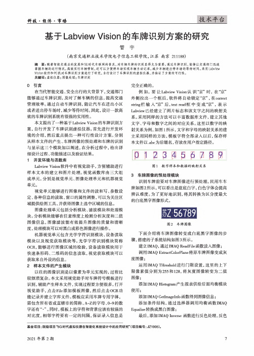
科菽.傕济•市杨技术平台基于Labview Vision的车牌识别方案的研究管宇(南京交通职业技术学院电子信息工程学院,江苏南京211188)摘要:随着智能交通业的发展和5G时代车联网的普及,对车辆车牌的识别显得尤为重要。
通过车牌识别,能够让交通部门迅速掌握车辆的运行情况,高效实行车辆管制,还可以方便停车场实现车辆自动记录,减少车辆进出停车场的等待时间。
采用Labview Vision软件和PC机对车牌识别方案进行了研究,自行设计了车牌识别的虚拟仪器,并验证了方案的可行性。
关键词:虚拟仪器;图像处理;车牌识别0引言在当代智能交通、安全出行的大背景下,交通部门能够通过车牌识别,及时了解车辆的信息,提高交通管理效率。
通过自动车牌识别,能让汽车在进出小区或者进出停车场时,减少等待时间。
因此,设计一款高效的车牌识别系统有很强的实用性。
本文提出了一种基于Labview Vision的车牌识别方案,自行开发了车牌识别虚拟仪器。
首先进行开发环境的介绍,然后重点提出一种可行性设计方案。
分别从样本文件的产生、车牌图像的预处理和车牌的识别与显示这三个模块加以阐述,在分析过程中,给出详细设计过程、功能描述以及验证结果。
1开发环境与函数库Labview Vision软件中有视觉助手,方便辅助进行样本文本的建立和图片处理。
视觉函数库由三大组成单元,分别是视觉单元、图像处理单元和机器视觉单元。
视觉单元能够进行图像和文件的读和写、参数设定、各种信息的读取、窗口的属性调整,可以为关注区域提供绘图工具,并获得图像上选中区域的信息。
图像处理单元包括分析模块、滤波模块和处理模块。
分析模块能够在任意维度上检测分析灰度和二值图像信息,图像滤波能有效提升图像的质量和清晰度,处理模块可以对黑白或彩色图像进行操作。
机器视觉单元包含光学字符识别模块、设备读取模块以及视觉获取模块等。
光学字符识别模块简称OCR,能够进行图像区域的检验,设备读取模块用于快速条形码、二维码的信息读取,视觉获取模块可以获取来自外设的信息。
电子教案《基于LabVIEW的应用程序设计》(李晴 钱声强)ppt KC10122002-c01-简易停车场管理系统硬件设计
串口通讯协议
停车场 管理
• 波特率19200bps,8位数据位,1位起始位,1位停止位,无校验。 • 命令帧格式:
• //(第一字节10代表帧头) • //(第二字节代表机器地址) • //(第三字节发送时是命令;返回时是数据长度)
5
读/写机器号
停车场 管理
• 读机器地址(GetMacNo)
发送命令: 10 FF
04
46 61 69 6C (‘Fail’)
With UID
发送命令: 10 FF 72 (‘r’) UID (8byte)
正确返回: 10 FF 05
加锁状态 (1byte)
错误返回: 10 FF 04
46 61 69 6C (‘Fail’)
block number (1byte) BlockData (4byte)
蜂鸣器BELL控制
9
读块
停车场 管理
• 读取一个Block (Read a block) Without UID
发送命令: 10 FF 正确返回: 10 FF 错误返回: 10 FF
52 (‘R’) block number (1byte)
05
加锁状态 (1byte) BlockData (4byte)
Without UID
发送命令: 10 FF 4C (‘L’) block number (1byte)
正确返回: 10 FF 04
44 6F 6E 65 (‘Done’)
错误返回: 10 FF 04
46 61 69 6C (‘Fail’)
With UID
发送命令: 10 FF 正确返回: 10 FF 错误返回: 10 FF
6C (‘l’) 04 04
基于LabVIEW图像法车牌智能识别系统
基于LabVIEW图像法车牌智能识别系统王党树;王新霞【摘要】车辆牌照自动识别是实现交通管理智能化的重要环节,设计中利用图像采集卡对经过的车辆车牌进行图像采集并传送至计算机,采用美国NI公司LabVIEW 软件,实现图像预处理、图像去噪以及图像增强等功能;然后根据车牌颜色特征对其准确定位,采用阈值法分割车牌字符;最后由OCR函数来识别字符,识别结果保存至相应数据中,可以进行相应的违章、违规智能交通管理,经实验该系统成功实现车牌识别识别率达99%.【期刊名称】《计算机测量与控制》【年(卷),期】2015(023)008【总页数】4页(P2871-2874)【关键词】车牌识别;LabVIEW;视觉开发模块【作者】王党树;王新霞【作者单位】西安科技大学电气与控制工程学院,西安710054;西安科技大学理学院,西安710054【正文语种】中文【中图分类】TM206智能化交通系统(intelligent transportation system,ITS)是一种准确、高效并且实时性很强的交通运输管理系统,该系统的搭建需要综合运用通讯、信息、控制、传感、计算机等各个方面的技术[1]。
其中汽车牌照识别技术[2](license plate recognition system,IPRS)是智能交通系统研究较为重要的领域,也是当今社会的热门研究课题,其主要的应用场所有:停车场、公路自动收费站、居民小区等。
而车辆牌照中的车牌号码是车辆身份信息的唯一标志,车牌信息的自动识别是实现交通管理系统智能化的前提。
车牌识别系统是一个集图像处理、模式识别等的高度智能化集成体系,其硬件主要由CCD摄像机、PCI图像采集卡和计算机构成,系统方案原理如图1所示。
当有车辆经过传感器时,传感器将产生电信号并传至PCI数据采集卡,采集卡进行数据采集,再将采集到的车辆图像信息传输到计算机上。
计算机对接收的图像预处理,图像处理后通过适当算法将图像中车牌区域定位出来,若欲对车牌进行识别还需将所定位出的车牌上的字符与其背景进行分割,提取车牌字符,最后经过字符识别处理达到车牌智能识别的功能。
基于matlab车牌识别系统设计与实现毕业设计(论文)

本科生毕业设计(论文)车牌识别系统设计与实现Design and Implementation of License Plate Recognition System总计:30页表格:1个插图:19幅南阳理工学院本科毕业设计(论文)车牌识别系统设计与实现Design and Implementation of License Plate Recognition System学院:电子与电气工程学院专业:电气工程及其自动化学生姓名:学号:指导教师(职称):评阅教师:完成日期:南阳理工学院Nanyang Institute of Technology毕业论文(设计)原创性声明本人所呈交的毕业论文(设计)是我在导师的指导下进行的研究工作及取得的研究成果。
据我所知,除文中已经注明引用的内容外,本论文(设计)不包含其他个人已经发表或撰写过的研究成果。
对本论文(设计)的研究做出重要贡献的个人和集体,均已在文中作了明确说明并表示谢意。
作者签名:日期:毕业论文(设计)授权使用说明本论文(设计)作者完全了解**学院有关保留、使用毕业论文(设计)的规定,学校有权保留论文(设计)并向相关部门送交论文(设计)的电子版和纸质版。
有权将论文(设计)用于非赢利目的的少量复制并允许论文(设计)进入学校图书馆被查阅。
学校可以公布论文(设计)的全部或部分内容。
保密的论文(设计)在解密后适用本规定。
作者签名:指导教师签名:日期:日期:注意事项1.设计(论文)的内容包括:1)封面(按教务处制定的标准封面格式制作)2)原创性声明3)中文摘要(300字左右)、关键词4)外文摘要、关键词5)目次页(附件不统一编入)6)论文主体部分:引言(或绪论)、正文、结论7)参考文献8)致谢9)附录(对论文支持必要时)2.论文字数要求:理工类设计(论文)正文字数不少于1万字(不包括图纸、程序清单等),文科类论文正文字数不少于1.2万字。
3.附件包括:任务书、开题报告、外文译文、译文原文(复印件)。
基于labview的车牌识别

识别流程图
图像预处理
预处理流程为:先选取一张图片,然后进行读取操作, 重新定义图像大小然后进行灰度化,提取绿色分量,然后 输出到下一帧。这一步骤可以大幅度地改进和完善车辆图 像,尤其是车牌区域的图像清晰度,能够更好的识别图像 。 灰度化:彩色图像包含着大量的颜色信息,不但在存储 上开销很大,而且在 处理上也会降低系统的执行速度。由 预处理流程为:先选取一张图片,然后进行读取操作,重新定义图像大小 然后进行灰度化,提取绿色分量,然后输出到下一帧。这一步骤可以大幅 于图 像的每 个 象素都具有三个 不同的颜 色分t,存在许 多 度地改进和完善车辆图像,尤其是车牌区域的图像清晰度,能够更好的识 与识别无关 的信息,不便于进一步的识别工作,因此在对 别图像。 图像进行识别等处理中 经常将彩色图像转变为灰度 图像,以加快处理速度。
labview提供了丰富的数据采集存储的库函数为用户提供了实现仪器编程与数据采集的便捷途径设计者无需写任何文格式的代码而是使用图形化的符号来描述程序的功能imaqvision工具包中含有300多种机器视觉和科学图象处理的函数库在labview中增加了机器视觉和图象处理的功能提供了大量的图象预处理图象分割图象理解函数库和图形化的工具模块用户只要在流程图中用图标连接器将所需要的子vi连接起来就可以完成对获得图像的预处理理解从而实现机器视觉
右图是阈值分割后的图像
字符识别处理
目前用于车牌字符识别(OCR)中的算法主要有:基于模 板匹配的OCR算法和基于人工神经网络的OCR算法。 基于模板匹配的OCR的基本过程是:首先对待识别字符进 行二值化并将其尺寸大小缩放为字符数据库中模板的大小 , 然后与所有的模板进行匹配,最后选最佳匹配作为结果 用人工神经网络OCR进行字符识别主要有两种方法: 一种 方法是先对待识别字符进行特征提取, 然后用所获得的特 征来训练神经网络分类器;另一种方法则充分利用神经网 络的特点, 直接把待处理图像输入网络,由网络自动实现 特征提取直至识别。 模板匹配的主要特点是实现简单,当字符较规整时对字符 图像的缺损、污迹干扰适应力强且识别率相当高,是车牌 字符识别的主要方法。
基于labview的车牌识别
字符识别处理
下图为字符识别的流程图
识别结果
如右图图GUI所示,系统 界面主要分为四大部分。 最左为所选车牌原图像, 右上为车牌定位后的图像, 右中为车牌分割后的车牌 图像,右下为系统识别的 车牌号码。
软件演示
系统的技术指标
1. 识别率
自然交通流量的识别率=全牌正确识别总数/实际通过的车辆总数
识别流程图
图像预处理
预处理流程为:先选取一张图片,然后进行读取操作, 重新定义图像大小然后进行灰度化,提取绿色分量,然后 输出到下一帧。这一步骤可以大幅度地改进和完善车辆图 像,尤其是车牌区域的图像清晰度,能够更好的识别图像 。 灰度化:彩色图像包含着大量的颜色信息,不但在存储 上开销很大,而且在 处理上也会降低系统的执行速度。由 预处理流程为:先选取一张图片,然后进行读取操作,重新定义图像大小 然后进行灰度化,提取绿色分量,然后输出到下一帧。这一步骤可以大幅 于图 像的每 个 象素都具有三个 不同的颜 色分t,存在许 多 度地改进和完善车辆图像,尤其是车牌区域的图像清晰度,能够更好的识 与识别无关 的信息,不便于进一步的识别工作,因此在对 别图像。 图像进行识别等处理中 经常将彩色图像转变为灰度 图像,以加快处理速度。
车牌定位处理和labview与matlab混合编程
图像经过二值化后,就可以进行车牌定位。通过对比原始 图片,我们可以发现二值化后的图像已经很接近正确的车 牌位置了,因此后期处理将通过这张图来找出车牌位置。 LabVIEW集成了大量图形界面的模板,自身功能强大,在 测试与测量、过程控制与处理、科学研究和分析等方面有 广泛的应用。但是,在实际应用中,对于一些需要进行大量数 据运算处理的复杂应用,LabVIEW并不能很好的满足系统 对运算速度等方面的要求。 Matlab是一种功能强、效率高、简单易学的数学软件,有 可靠的数值计算和符号计算功能、强大的绘图功能、简单 易学的语言体系以及为数众多的应用工具。用LabVIEW 与Matlab之间的混合编程,在功能上互补,具有实用价值。
基于LabVIEW的HSI颜色空间和数学形态学车牌识别系统
长宽比为 3.14。设 粒 子 的 长 宽 之 比 为 F,则 F∈ 候,图像的处理效果较好。
[2.5,4],利 用 F值 将 车 牌 提 取 出 来。 同 时 将 图
c. 在 经 过 上 述 的 处 理 后 ,当 图 片 拍 摄 的 效 果
片的位置信息输送出去。
不 是 很 好 时,用 LabVIEW 工 具 包 中 的 IMAQ
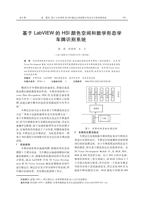
图 1 车牌识别系统处理过程 2 车 牌 定 位 算 法 验 证
车牌定位是指根据车牌的特征来对车牌的位 置进行有效的定位。车牌定位的准确性直接影响 到后续的处理过程。由于车牌最明显的特征是车 牌的颜色,所 以 基 于 颜 色 的 定 位 是 最 简 单 的。 在 NIVisionDevelopmentModule中,有 RGB、HSV、 HSB及 HSI等色彩 空 间。 由 于 HSI空 间 中 色 调、 饱和度和灰度三 者 互 相 独 立,而 RGB空 间 由 于 3 个分量之间相 互 联 系,其 中 任 何 一 个 的 改 变 都 会 导致 另 外 两 个 需 要 跟 着 改 变,所 以 采 用 HSI作 为 提取车 牌 的 颜 色 空 间。 RGB颜 色 空 间 转 到 HSI
随 着 汽 车 年 销 售 量 的 快 速 增 长,智 能 交 通 系 统显现出越来越重要的作 用。车 牌 识 别 系 统 (Li censePlateRecognition,LPR)作 为 智 能 交 通 系 统 的首个环节,广 泛 应 用 于 封 闭 小 区 车 辆 出 入 的 管 理、高速公路车 辆 实 时 监 控 及 智 能 化 停 车 库 等 方 面 。 [1]
a.将含有车牌的图片从 RGB颜色空间转到
当对车牌进行 完 定 位 之 后,为 了 提 高 车 牌 识