JANTXV2N6796U中文资料
2N6661JANTX中文资料

2N6661JAN/JANTX/JANTXVVishay SiliconixDocument Number: 70225 S-04279—Rev. B, 11-1JAN Qualified N-Channel 90-V (D-S) MOSFETsFEATURES BENEFITS APPLICATIONSD Military QualifiedD Low On-Resistance: 3.6 WD Low Threshold: 1.6 VD Low Input Capacitance: 35 pF D Fast Switching Speed: 6 ns D Low Input and Output Leakage D Guaranteed ReliabilityDLow Offset VoltageD Low-Voltage OperationD Easily Driven Without BufferD High-Speed CircuitsD Low Error VoltageD Military ApplicationsD Direct Logic-Level Interface: TTL/CMOSD Drivers: Relays, Solenoids, Lamps, Hammers,Displays, Memories, Transistors, etc.D Battery Operated SystemsD Solid-State RelaysTO-205AD(TO-39)Top ViewDevice MarkingSide ViewJAN2N6661*“S” fllxxyy“S” = Siliconix Logof = Factory Codell = Lot Traceabilityxxyy = Date Code*Note: or JANTX2N6661JANTXV2N6661Notesa.Pulse width limited by maximum junction temperature.b.Not required by Military Spec.2N6661JAN/JANTX/JANTXV Vishay Siliconix 11-2Document Number: 70225 S-04279—Rev. B, 16-Jul-01Notesa.For DESIGN AID ONLY, not subject to production testing.VNDQ09b.Pulse test: PW v300 m s duty cycle v2%.c.Switching time is essentially independent of operating temperature.d.For typical characteristics curves see the 2N6661/VN88AFD data sheet.Document Number: 91000Revision: 18-Jul-081DisclaimerLegal Disclaimer NoticeVishayAll product specifications and data are subject to change without notice.Vishay Intertechnology, Inc., its affiliates, agents, and employees, and all persons acting on its or their behalf (collectively, “Vishay”), disclaim any and all liability for any errors, inaccuracies or incompleteness contained herein or in any other disclosure relating to any product.Vishay disclaims any and all liability arising out of the use or application of any product described herein or of any information provided herein to the maximum extent permitted by law. The product specifications do not expand or otherwise modify Vishay’s terms and conditions of purchase, including but not limited to the warranty expressed therein, which apply to these products.No license, express or implied, by estoppel or otherwise, to any intellectual property rights is granted by this document or by any conduct of Vishay.The products shown herein are not designed for use in medical, life-saving, or life-sustaining applications unless otherwise expressly indicated. Customers using or selling Vishay products not expressly indicated for use in such applications do so entirely at their own risk and agree to fully indemnify Vishay for any damages arising or resulting from such use or sale. Please contact authorized Vishay personnel to obtain written terms and conditions regarding products designed for such applications.Product names and markings noted herein may be trademarks of their respective owners.元器件交易网。
Xvision X2R16N 16通道H.265 NVR产品说明书

X2R16N-12TB X2R16N-1TB X2R16N-2TB X2R16N-3TB X2R16N-4TB X2R16N-6TB X2R16N-8TBProfessional 16 Camera HD-IP 5MP H264 NVRX2R16NVersion 1Full HD 1080P Real-Time Recording Pentaplex OperationUSB/Network BackupHDMI & VGA Monitor Output16 PoE Ports for Direct ConnectionP2P Remote Access via Smartphone, Tablet, PC & MacPRO IPHDFeaturesThe Xvision X2R16N 16 Channel H.265 NVR o ers the very latest in digital recording. The unit can record up to 5 Megapixel Super High De nition images. It has an built-in 16-port PoE switch to allow simple direct connection to the cameras o ering either auto or manual allocation of IP addresses for the connected cameras.The NVR provides a full HD 1080P monitor output via VGA or HDMI and can be controlled from the front panel touch sensitive controls or by supplied remote control or USB mouse. The NVR uses P2P technology for quick, seamless Network connectivity and is supplied with a dedicated Smartphone/Tablet App that can also receive Push Video alerts, showing alarms detected by Video Motion Detection. The NVR has a simple back-up procedure via USB or Network and is fully ONVIF compliant. Technical Speci cationsBrand XVISION Model Number X2R16N IP Camera Support ONVIF, Xvision PRO-HD Compression H264 / H265Recording Resolution 1080P (1920x1080) / 720P (1280x720) / D1 (704x576) Recording Bandwidth200Mbps D1: 16 Channel Real-Time, 720P : 12 Channel Real-Time, 1080P : 6 Channel Real-Time Live/PlaybackVideo Output 1x HDMI, 1x VGA Bit Rate 32-8192kbps Recording ModeContinuous / Manual / Motion Detection / Sensor / Alarm Alarm Input / OutputAutomatic Electronic Shutter Display Resolution 1920x1080, 1280x1024, 1440x900, 1280x720, 1024x768Ethernet RJ45 Port (1000M)Mobile AppiPhone, iPad, Android, Tablet - XIQ Mobile CMS USB1x 3.0 USB for backup/upgrade, 2x 2.0 USB for Mouse Max. Hard Drive Supported 2x 6TB (12TB Total)Controls USB Mouse, Remote Control PoE Ports 16e-Sata Optional ONVIF ONVIF Version 2.0 Power Supply NVR : DC 20V 190W PoE Switch : DC48V Dimension (WxHxD) mm 380x50x340X2R16N8 CH Input / 1 CH Output All speci cations shown are subject to change without notice, please con rm up-to-date details when ordering. All network speci cations and recording times are based upon theoretical scenarios. Actual performances will vary depending on external factors. No liability will be accepted by Y3K for any errors or omissions in this information. All relevant trade marks acknowledged. © Y3K (Europe) Limited 2015DISTRIBUTED BY1/4/8/16Display SplitX2R16N-12TB X2R16N-1TB X2R16N-2TB X2R16N-3TB X2R16N-4TB X2R16N-6TB X2R16N-8TB。
集特海光系列
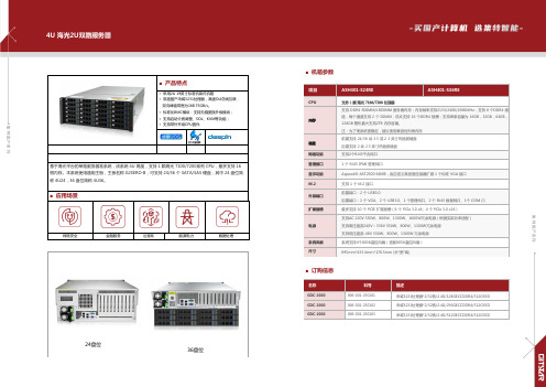
■ 产品特点• 采用2U 19英寸标准机架式机箱• 双路国产申威3231处理器,高速DLI 总线互联, 双向峰值带宽为168.75GB/s 。
• 标准化BMC 模块:支持无缝更换升级模块; • 支持启动介质调整、SOL 、KVM 等功能; • 支持带外升级CPU 固件基于海光平台的单路服务器准系统,该系统 4U 高度,支持 1 颗海光 7100/7200系列 CPU ,最多支持 16 根内存。
本系统使用通用主板,主板名称 G2SERO-B ,可支持 24/36 个 SATA/SAS 硬盘,其中 24 盘位简称 4U24,36 盘位简称 4U36。
■ 应用场景网络安全金融服务运营商能源电力数据处理24盘位36盘位■ 机箱参数项目ASH401-S24REASH401-S36RECPU支持 DDR4 RDIMM/LRDIMM 服务器内存;内存频率支持2133/2400/2666MHz ;支持 8 个DDR4 通道,每个通道支持 2 个 DIMM ,总共支持 16 个DDR4 插槽;支持单条容量为 16GB ,32GB ,64GB ,128GB 整机最大支持2TB 内存容量。
注:为了使系统更稳定,建议使用兼容性列表内存前置支持 24/36 块 3.5 或2.5 英寸热插拔硬盘 后置支持 2 块 2.5 英寸热插拔硬盘 网络功能 支持2个RJ45千兆网口 管理接口 1 个 RJ45 IPMI 管理网口显示功能 Aspeed® AST2500 64MB,由自定义高密度连接器扩展 1 个标准 VGA 接口 M.2 支持 1 个 M.2 接口 外部端口 前置端口:2 个 USB3.0后置端口:1 个 VGA 、2 个 USB3.0、1 个管理网口、2 个 RJ45 数据网口、1个 COM 口 扩展插槽最多支持 10 个 PCIE 扩展插槽(6 个 PCIe 3.0 x8;4 个 PCIe 3.0 x16)电源支持AC 220V 550W 、800W 、1300W 、1600W 冗余电源(根据实际功率适配)支持高压直流240V ~336V 550W 、800W 、1300W 冗余电源 支持低压直流-48V 550W 、800W 、1300W 冗余电源系统风扇 系统支持4个8038温控风扇(选配8056温控风扇) 尺寸695mm*433.4mm*176.5mm (长*宽*高)■ 订购信息名称料号描述GDC-2000 806-001-250101 申威3231处理器*2/32核/2.4G/128GECCDDR4/512GSSD GDC-2000 806-001-250102 申威3231处理器*2/32核/2.4G/256GECCDDR4/512GSSD GDC-2000806-001-250103申威3231处理器*2/32核/2.4G/512GECCDDR4/512GSSD集 特 国 产 系 列集 特 国 产 系 列■ 产品特点• 单个SP3 Socket ,支持海光7100/7200系列处理器 • 总共支持 16 个 DDR4 插槽;整机最大支持 2TB • 单板上面有10组 PCIE 3.0扩展插槽• 1 个 M.2 Key M SSD 插槽,只支持2280 尺寸及PCIe3.0X4信号• 集成了2个千兆网口 ,采用 I350-AM2芯片GME-5001是一款单路 CPU 标准 E-ATX 服务器主板,支持海光 7100、7200 系列处理器。
Cavium_OCTEON31xx30xx_Chinese_v16

Cavium Networks Contact: Cavium NetworksAngel Atondo 805 East Middlefield RoadTel: (650) 623-7033 Mountain View, CA 94043 Email: angel.atondo@ Phone: (650) 623-7000Cavium Networks 发布业界最全的基于单核与双核 MIPS64®面向下一代智能网络的 OCTEON™ 处理器新的 OCTEON SOC 处理器为网络、无线、控制和存储应用提供处理器为网络、无线、控制和存储应用提供了了高度集成高度集成和和有成本效益有成本效益的的 64 位计算的解决方案2006 年 1 月 30 日,美国加州日,美国加州山景城山景城 —— 安全、网络服务和嵌入式处理器解决方案的世界领导者 Cavium Networks 今天发布 10 款新的价格从 $20 以下开始基于单核和双核 MIPS64 高度集成的处理器。
为了突破下一代网络、无线、控制和存储应用对特性、性价比和功耗的需求,新的 SOC (System on Chip )集成了定制的 MIPS64 处理器和业界最先进的多层应用(multi-layer applications )加速和安全处理硬件,以及丰富的可配置的网络接口。
新的 OCTEON CN31XX 和 CN30XX 系列处理器与目前市场上领先的多核处理器家族 CN38XX 系列保持软件兼容。
OCTEON 产品家族目前提供从单核到 16 核的业界最具可扩展性和兼容的 MIPS64 处理器产品线,这样 OEM 厂商可以使用同一套通用的软件开发不同性能和价格点的设备,大量的降低了开发成本和缩短了产品面市时间。
OCTEON 处理器被广泛的设计进了各种网络设备,包括路由器、交换机、统一威胁管理(UTM ,Unified Threat Management )设备、应用认知(Application-aware )网关、三网合一(Triple-play )网关、无线局域网(WLAN )、3G 接入和聚合设备以及网络存储设备等。
JANTXV1N6642U中文资料
6 LAKE STREET, LAWRENCE, MASSACHUSETTS 01841 PHONE (978) 620-2600 FAX (781) 689-0803 WEBSITE:
157
元器件交易网
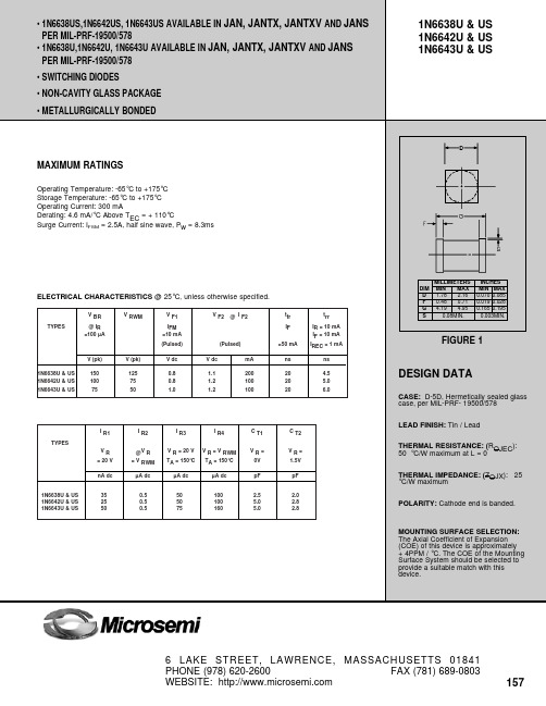
IN6638U&US, IN6642U&US
1000
100
150ºC
IR - Reverse Current - (µA)
10
100º
1
C
0.1
25ºC
.01
-65ºC
-65ºC
1
25º
C
NOTE :
All temperatures shown on graphs are junction temperatures
.001 20 40 60 80 100 120 140 Percent of Reverse Working Voltage (%) FIGURE 3 Typical Reverse Current vs Reverse Voltage
1N6638U & US 1N6642U & US 1N6643U & US
MAXIMUM RATINGS
Operating Temperature: -65°C to +175°C Storage Temperature: -65°C to +175°C Operating Current: 300 mA Derating: 4.6 mA/°C Above TEC = + 110°C Surge Current: IFSM = 2.5A, half sine wave, Pw = 8.3ms
DIM D F G S
ZDT6790中文资料(Zetex Semiconductors)中文数据手册「EasyDatasheet - 矽搜」

转换频率
fT
输入电容
Cibo
输出电容
Cobo
开关时间
t on
t off
*脉冲条件下进行测定.脉冲宽度= 300 对于典型特性曲线图看FZT690数据表.
amb = 25°C).
MIN. TYP. 最大.部件
45
V
45
V
5
V
0.1 µA
0.1 µA
0.1 V 0400 150
工作和存储温度范围T
符号
VCBO VCEO VEBO ICM IC
j:Tstg
NPN PNP
45
-50
45
-40
5
-5
6
-6
2
-2
-55到+150
热特性
参数
符号
值
在T总功率耗散
amb = 25°C*
Ptot
"关于"任何单一芯片
2.25
这两个死""平等
2.75
减免上述25°C *
"关于"任何单一芯片
18
这两个死""平等
22
热电阻 - 结到环境*
"关于"任何单一芯片
55.6
这两个死""平等
45.5
*可以消散假设设备功率是安装在一个典型方式上与铜等于2英寸见方印刷电路板.
单元
V V V A A °C
单元
W W
毫瓦/°C 毫瓦/°C
°C/ W °C/ W
芯片中文手册,看全文,戳
ZDT6790
芯片中文手册,看全文,戳
SM-8互补中功率
VQFN16中文资料

4.0 4.2
13
16
15
11
10
元器件交易网
Appendix
Notes
No technical content pages of this document may be reproduced in any form or transmitted by any means without prior permission of ROHM CO.,LTD. The contents described herein are subject to change without notice. The specifications for the product described in this document are for reference only. Upon actual use, therefore, please request that specifications to be separately delivered. Application circuit diagrams and circuit constants contained herein are shown as examples of standard use and operation. Please pay careful attention to the peripheral conditions when designing circuits and deciding upon circuit constants in the set. Any data, including, but not limited to application circuit diagrams information, described herein are intended only as illustrations of such devices and not as the specifications for such devices. ROHM CO.,LTD. disclaims any warranty that any use of such devices shall be free from infringement of any third party's intellectual property rights or other proprietary rights, and further, assumes no liability of whatsoever nature in the event of any such infringement, or arising from or connected with or related to the use of such devices. Upon the sale of any such devices, other than for buyer's right to use such devices itself, resell or otherwise dispose of the same, no express or implied right or license to practice or commercially exploit any intellectual property rights or other proprietary rights owned or controlled by ROHM CO., LTD. is granted to any such buyer. Products listed in this document are no antiradiation design.
2N2906中文资料

MIN. MAX. UNIT
−
−60
V
−
−40
V
−
−60
V
−
−5
V
−
−600 mA
−
−800 mA
−
−200 mA
−
400
mW
−
1.2
W
−65
+150 °C
−
200
°C
−65
+150 °C
VALUE 438 146
UNIT K/W K/W
1997 Jun 02
3
Philips Semiconductors
DC current gain 2N2906A
collector-emitter saturation voltage base-emitter saturation voltage collector capacitance emitter capacitance transition frequency
PNP switching transistors
Product specification
2N2906; 2N2906A
CHARACTERISTICS Tamb = 25 °C unless otherwise specified
SYMBOL
PARAMETER
CONDITIONS
MIN. MAX. UNIT
2N2906 2N2906A emitter-base voltage collector current (DC) peak collector current peak base current total power dissipation
- 1、下载文档前请自行甄别文档内容的完整性,平台不提供额外的编辑、内容补充、找答案等附加服务。
- 2、"仅部分预览"的文档,不可在线预览部分如存在完整性等问题,可反馈申请退款(可完整预览的文档不适用该条件!)。
- 3、如文档侵犯您的权益,请联系客服反馈,我们会尽快为您处理(人工客服工作时间:9:00-18:30)。
— 45
1.8 — 4.3 —
nH
Measured from drainpadto Modified MOSFET symbol show-
die.
ing the internal inductances.
Measured from center of source pad to the end of source bonding wire.
Product Summary
Part Number
BVDSS
IRFE130
100V
RDS(on) 0.18Ω
Features:
n Hermetically Sealed n Simple Drive Requirements n Ease of Paralleling n Small footprint n Surface Mount n Lightweight
HEXFET transistors also feature all of the well-established advantages of MOSFETs, such as voltage control, very fast switching, ease of paralleling and electrical parameter temperature stability. They are well-suited for applications such as switching power supplies, motor controls, inverters, choppers, audio amplifiers and high-energy pulse circuits, and virtually any application where high reliability is required.
IRFE130, JANTX-, JANTXV-, 2N6796U Units
8.0
5.0
A
32
25
W
0.17
W/K
±20
V
134
mJ
8.3
V/ns
-55 to 150
oC
300 ( for 5 seconds)
0.42 (typical)
g
11/13/97
IRFE130, JANTX-, JANTXV-, 2N6796U Device Electrical Characteristics @ Tj = 25°C (Unless Otherwise Specified)
RthJPCB Junction-to-PC Board
Min Typ Max Units
— — 5.0 K/W
— — 19
Test Conditions Soldered to a copper clad PC board
Details of notes through are on the last page
100Volt, 0.18Ω, HEXFET The leadless chip carrier (LCC) package represents the logical next step in the continual evolution of surface mount technology. The LCC provides designers the extra flexibility they need to increase circuit board density. International Rectifier has engineered the LCC package to meet the specific needs of the power market by increasing the size of the bottom source pad, thereby enhancing the thermal and electrical performance. The lid of the package is grounded to the source to reduce RF interference.
Internal Source Inductance
Min 100 —
— — 2.0 3.0 — —
— — — — — — — — — —
—
Typ Max Units —— V 0.11 — V/°C
Test Conditions VGS =0 V, ID = 1.0mA Reference to 25°C, ID = 1.0mA
Parameter
Min Typ Max Units
Test Conditions
IS Continuous Source Current (Body Diode) ISM Pulse Source Current (Body Diode)
— — 8.0 — — 32
A Modified MOSFET symbol showing the integral reverse p-n junction rectifier.
— — 970 nC
VDD ≤ 50V
Intrinsic turn-on time is negligible. Turn-on speed is substantially controlled by LS + LD.
Thermal Resistance
Parameter
RthJC
Junction-to-Case
TJ = 25° C TJ = 150° C
10
1
0.1 4
V DS = 50V 20µs PULSE WIDTH
5
6
7
8
9
10
VGS , Gate-to-Source Voltage (V)
Fig 3. Typical Transfer Characteristics
RDS(on) , Drain-to-Source On Resistance (Normalized)
VGS = 0V, TJ = 125°C
— 100 — -100 nA — 29
VGS = 20 V VGS = -20V VGS = 10V, ID = 8.0A
— 6.5 nC — 17
VDS = Max Rating x 0.5
— 30 — 75 — 40 ns
VDD = 50V, ID = 8.0A, RG = 7.5Ω
Parameter
BVDSS
Drain-to-Source Breakdown Voltage
∆BVDSS/∆TJ Temperature Coefficient of Breakdown Voltage
RDS(on)
Static Drain-to-Source On-State Resistance
1
4.5V
0.1 0.1
20µs PULSE WIDTH TJ = 150 °C
1
10
100
VDS , Drain-to-Source Voltage (V)
Fig 2. Typical Output Characteristics
ID , Drain-to-Source Current (A)
100
1
10
100
VDS , Drain-to-Source Voltage (V)
Fig 1. Typical Output Characteristics
I D, Drain-to-Source Current (A)
100 10
VGS
TOP
15V
10V
8.0V
7.0V
6.0V
5.5V
5.0V
BOTTOM 4.5V
ID , Drain-to-Source Current (A)
IRFE130, JANTX-, JANTXV-, 2N6796U Device
100 10
VGS
TOP
15V
10V
8.0V
7.0V
6.0V
5.5V
5.0V
BOTTOM 4.5V
1
4.5V
0.1 0.1
20µs PULSE WIDTH TJ = 25 °C
VGS(th) gfs IDSS
Gate Threshold Voltage Forward Transconductance Zero Gate Voltage Drain Current
IGSS IGSS Qg Qgs Qgd td(on) tr td(off) tf LD
LS
Gate-to-Source Leakage Forward Gate-to-Source Leakage Reverse Total Gate Charge Gate-to-Source Charge Gate-to-Drain (‘Miller’) Charge Turn-On Delay Time Rise Time Turn-Off Delay Time Fall Time Internal Drain Inductance
VSD trr QRR
ton
Diode Forward Voltage Reverse Recovery Time Reverse Recovery Charge
Forward Turn-On Time
— — 1.5 V Tj = 25°C, IS = 8.0A, VGS = 0V
— — 300 ns Tj = 25°C, IF = 8.0A, di/dt ≤ 100A/µs
— 0.18 — 0.207 Ω