电子类专业考试1007
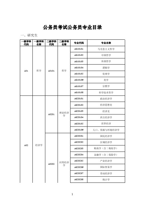
公务员考试录用公务员专业目录
A0823
交通运输 工程
A082302 A082303 A082304 A082401
A0824
船舶与海 洋工程
A082402 A082403 A082501
A0825
航空宇航 科学与技 术
A082502 A082503 A082504 A082601
电机与电器 电力系统及其自动化 高电压与绝缘技术 电力电子与电力传动 电工理论与新技术 物理电子学 电路与系统 微电子学与固体电子学 电磁场与微波技术 通信与信息系统 信号与信息处理 控制理论与控制工程 检测技术与自动化装置 系统工程 模式识别与智能系统 导航、制导与控制 计算机系统结构 计算机软件与理论 计算机应用技术 建筑历史与理论 建筑设计及其理论 城市规划与设计(含:风景园林规 划与设计) 建筑技术科学 岩土工程 结构工程 市政工程
A0815
水利工程
A081503 A081504 A081505 A081601
A0816
测绘科学 与技术
A081602 A081603
A08
工学
A081701 A081702 A0817 化学工程 与技术 A081703 A081704 A081705 A081801 A0818 地质资源 与地质工 程 A081802 A081803 A081901 A0819 矿业工程 A081902 A081903 A082001 A0820 石油与天 然气工程 A082002 A082003 A082101 纺织科学 与工程
A0708
6
A0712 A0713 A0714
科学技术 史(分学 科,可授 生态学 统计学 (可授理 学、经济 力学(可 授工学、 理学学 位)
江苏省普通高校“专转本”选拔考试电子信息专业大类专业综合基础理论考试大纲

江苏省普通高校“专转本”选拔考试电子信息专业大类专业综合基础理论考试大纲一、考试性质电子信息专业大类专业综合科目基础理论考试是为江苏省普通高校招收电子信息专业大类的“专转本”学生而设置的、具有选拔性质的全省统一考试。
其目的是科学、公平、有效地测试考生在高职(专科)阶段相关专业知识、基本理论与方法的掌握水平。
考试评价的标准是报考该专业大类的高职(专科)优秀毕业生应能达到的及格或及格以上水平,以利于各普通本科院校择优选拔,确保招生质量。
二、适用专业本考试大纲适用于测控技术与仪器(080301)、微电子科学与工程(080704)、光电信息科学与工程(080705)、农业电气化(082303)、电气工程及其自动化(080601)、电子信息工程(080701)、电子科学与技术(080702)、通信工程(080703)、信息工程(080706)、电子信息科学与技术(080714)、自动化(080801)、建筑电气与智能化(081004)。
三、命题原则科学、公平、有效地测试考生在高职(专科)阶段电子信息专业大类专业知识、基本理论与方法的掌握水平。
有利于对接考生在高职(专科)阶段与本科阶段的专业学习。
(一)课程A:电路基础【考查目标】1直流电路熟练掌握回路电流法、节点电压法及其应用;叠加定理、戴维南定理和诺顿定理的内容、适用范围,计算电路的电位、电压、电流、功率的各种应用方法。
掌握KCL、KVL,能熟练的结合参考方向列KCL、KVL方程求解电路的电流和电压。
熟悉支路电流法、网孔电流分析法及其应用、替代定理的内容及应用。
理解支路、节点、网孔、回路的概念;电路方程分析法的基本思路、线性电路、叠加定理的概念、等效变换的概念。
2暂态分析理解动态电路的换路过程。
掌握一阶电路零输入、零状态以及全响应。
掌握三要素法。
3交流电路熟练掌握正弦交流电的三要素(周期、频率、初相)的表示方式、正弦交流电流和电压的瞬时值、最大值、有效值的物理含义和计算;同频率正弦量的相量表示、相位差;正弦量的加减运算与相量运算的对应关系;线性时不变电阻、电感、电容元件伏安特性的相量形式;KCL、KVL相量形式;正弦交流电路中负载获得最大功率的条件;谐振电路工作条件。
电子试题及答案大全要点

11级数字电路复习题及参考答案一、单选题1. 同或逻辑对应的逻辑图是( )。
A.B.C.D.答案:A2. 在下列逻辑电路中,不是组合逻辑电路的是( ) 。
A. 译码器B. 编码器C. 全加器D. 寄存器答案:D3. 用触发器设计一个同步十七进制计数器所需要的触发器数目是( ) 。
A. 2B. 3C. 4D. 5答案:D4. 在下列各图中,或非逻辑对应的逻辑图是( ) 。
A. B.C. D.答案:B5. 在何种输入情况下,“或非”运算的结果是逻辑“1” 。
A. 全部输入是“0”B. 任意输入是“1”C. 仅一输入是“1”D. 全部输入是“1”答案:A6. 一个班级中有四个班委委员,如果要开班委会,必须这四个班委委员全部同意才能召开,其逻辑关系属于( )逻辑。
a.与;b. 或;c.非;d.与非 答案: a7. 在一个四变量逻辑函数中,( )为最小项。
a.AACD ;b.ABC ;c.ABCD ;d.()AB C D +答案:c8. 一个4路数据选择器,其地址输入(选择控制输入)端有( )个。
A. 2个 B. 3个 C. 4个 D. 5个 答案:A9. 由与非门构成的基本RS 触发器的输入端为R 、S ,则其约束条件为( )。
A. RS=0 B. R+S=1 C. RS=1 D. R+S=0 答案:A10. 在下列各图中,异或逻辑对应的逻辑图是( )。
A.B.C.D. 答案:D11. JK 触发器在CP 脉冲作用下,欲使 n+1nQ =Q , 则对输入信号描述不正确的是( )。
A. J =K =1B. J =Q ,K =QC.J =Q , K =Q D. J =Q ,K =1答案:B12. 当异步置数端I R S D D ==时,输出状态是在CP 由1变0时刻发生变化,且与CP=1期间输入状态变化无关,只取决于CP 由1变0前瞬间输入状态而定的触发器是( )。
A. 基本RS 触发器B. D 锁存器C. 同步JK 触发器D. 负边沿JK 触发器 答案:D13. 时序逻辑电路中一定包含( )。
电子类专业试题及答案大全
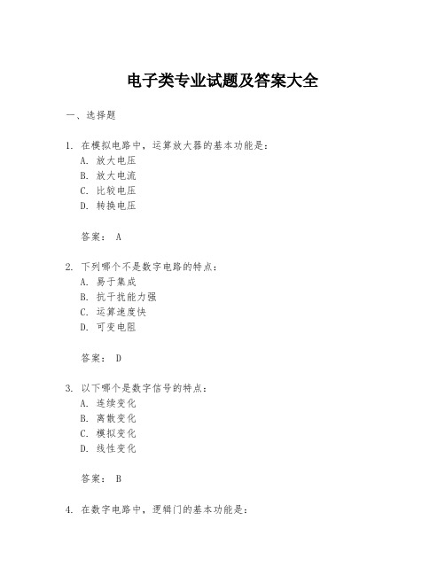
电子类专业试题及答案大全一、选择题1. 在模拟电路中,运算放大器的基本功能是:A. 放大电压B. 放大电流C. 比较电压D. 转换电压答案: A2. 下列哪个不是数字电路的特点:A. 易于集成B. 抗干扰能力强C. 运算速度快D. 可变电阻答案: D3. 以下哪个是数字信号的特点:A. 连续变化B. 离散变化C. 模拟变化D. 线性变化答案: B4. 在数字电路中,逻辑门的基本功能是:A. 放大信号B. 转换信号C. 逻辑运算D. 滤波答案: C5. 以下哪个不是半导体材料:A. 硅B. 锗C. 铜D. 砷化镓答案: C二、填空题1. 在数字电路中,最基本的逻辑门有______、与门、非门等。
答案:或门2. 电子电路中,三极管通常分为______型和NPN型。
答案:PNP型3. 微处理器的指令集架构(ISA)决定了它能够执行的______。
答案:指令类型4. 在电子电路中,电容的单位是______。
答案:法拉5. 模拟信号与数字信号的主要区别在于模拟信号是______变化的,而数字信号是离散变化的。
答案:连续三、简答题1. 简述什么是模拟信号和数字信号,并说明它们的主要区别。
答案:模拟信号是指随时间连续变化的信号,它可以表示任何连续变化的量,如声音、温度等。
数字信号则是离散的,它只能表示有限数量的状态,通常用二进制数表示。
主要区别在于模拟信号是连续的,而数字信号是离散的;模拟信号可以无限精确,数字信号则有量化误差;模拟信号容易受到噪声干扰,而数字信号具有较强的抗干扰能力。
2. 解释什么是集成电路,并简述其主要优点。
答案:集成电路是一种将大量电子元件集成在一个小型硅芯片上的技术。
其主要优点包括:体积小、重量轻、功耗低、可靠性高、生产成本低以及性能稳定。
四、计算题1. 假设有一个串联电路,其中包含一个电阻R1=100Ω,一个电容C1=10μF,以及一个电源V=12V。
计算在t=5ms时电容C1上的电压。
泰美电子1006直流毫伏源和1007直流毫伏电位计 源用户手册说明书
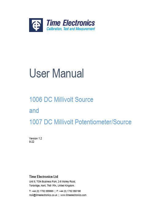
User Manual1006 DC Millivolt Sourceand1007 DC Millivolt Potentiometer/SourceVersion 1.29-22Time Electronics LtdUnit 5, TON Business Park, 2-8 Morley Road,Tonbridge, Kent, TN9 1RA, United Kingdom.T: +44 (0) 1732 355993 | F: +44 (0) 1732 350198***********************.uk|© 2022 Time Electronics Ltd.All rights reserved.Nothing from this manual may be multiplied, or made public in any form or manner, either electronically or hard copy, without prior written consent from Time Electronics Ltd. This also applies to any schematics, drawings and diagrams contained herein.This manual provides operating and safety instructions for the Time Electronics product. To ensure correct operation and safety, please follow the instructions in this manual. Time Electronics reserves the right to change the contents, specifications and other information contained in this manual without notice.Contents1Introduction (4)1.11006 DC Millivolt Source (4)1.21007 DC Millivolt Potentiometer and Source (5)1.3Specifications (6)2Controls (7)2.11006 Controls (7)2.21007 Controls (8)3Operating Instructions (9)3.1Battery Insertion (9)3.21006/1007 mV Source Operation (9)3.31007 mV Potentiometric Null Operation (10)4Servicing and Calibration (11)4.1Internal Preset Controls (11)4.2Calibration and Adjustment (11)5Warranty and Servicing (14)1Introduction1.11006 DC Millivolt SourceFeatures• 3 ranges:0 to 999.9mV (0.1 mV steps)0 to 99.99mV (10 µV steps)0 to 9.999mV (1 µV steps)•Accuracy 0.02 %•20 mA output current•Short circuit and overload protected•Safety terminals•Removable protective cover•Powered by 6 x AA batteries•100 hours typical battery life•Optional carry caseDescriptionThe 1006 is an accurate millivolt source suitable for voltage injection applications.Three output ranges are provided to give adjustable output values from 1 µV to 1 V with a basic 0.02 % accuracy. For signal injection, the operator needs to switch on, check the battery condition, select the range, and set the required voltage using the thumbwheel switches. The 1006 uses a precision bandgap reference device, with low temperature coefficient resistors to give a highly stable output.Power is provided by 6 AA batteries. Battery life is several months, depending on usage. The battery condition is monitored by an indicator situated on the top of the unit.The 1006 has up to 20 mA drive current and is short circuit and overload protected.An off/normal/reverse output polarity switch is provided.Connection is via safety terminals that are compatible with 4 mm shrouded plugs, as well as standard plugs, bare wires, and spade terminals.The unit comes fitted with an ergonomic rubber cover providing increased protection and durability. It has a textured grip for comfortable handling and top/bottom openings to place labels. It is easy to remove if the user prefers a stand-alone unit or to house the instrument in the optional carry case.The unit is simple to operate and does not require standardisation or calibration prior to use.1.21007 DC Millivolt Potentiometer and SourceFeatures• 3 ranges:0 to 999.9mV (0.1 mV steps)0 to 99.99mV (10 µV steps)0 to 9.999mV (1 µV steps)•Accuracy 0.02 %• 1 µV resolution null•20 mA output current•Short circuit and overload protected•Safety terminals•Removable protective cover•Powered by 6 x AA batteries•100 hours typical battery life•Optional carry caseDescriptionThe 1007 includes all the features of the 1006 with the addition of a microvolt null balance display. This enables it to be used for potentiometric voltage measurement in addition to its function as a calibrator. The null zero and sensitivity are adjustable via front panel controls - maximum sensitivity enables null balance to resolve 1 µV.Applications are essentially those of conventional potentiometers with the following significant advantages:•No standardisation is required.•20 mA output current.•Output remains stable without re-adjustment.•Electronic null with microvolt sensitivity.Connection is via safety terminals that are compatible with 4 mm shrouded plugs, as well as standard plugs, bare wires, and spade terminals.The unit comes fitted with an ergonomic rubber cover providing increased protection and durability. It has a textured grip for comfortable handling and top/bottom openings to place labels. It is easy to remove if the user prefers a stand-alone unit or to house the instrument in the optional carry case.The 1007 is simple to operate and does not require standardisation or calibration before use. It is only necessary to zero the null amplifier prior to making a measurement.1.3SpecificationsOutput:0 to999.9 mV in 3 ranges:0 to 999.9 mV in 0.1 mV steps0 to 99.99 mV in 10 μV steps0 to 9.999 mV in 1 μV stepsAccuracy:± (0.02 % of setting + 0.02 % of range + 1 μV)Output Resistance:Less than 0.2 Ω on 1 V and 100 mV ranges. 1 Ω on 10 mV range. Maximum Output Current:999.9mV and 99.99mV ranges: 20 mA.9.999mV range: Up to short circuit value although it should benoted that loads of less than 1 kΩ will give greater than 0.1 % error. Output Voltage Stability:Less than 60 ppm/°C.Less than 100 ppm per 3 month. (non cumulative)Operating Temperature:-10 °C to + 60 °C.Output Polarity:Positive or negative switch selected. A centre ‘off’ position is also provided. Output Noise Level:Less than 30 ppm of full scale.Reference Source: A precision bandgap reference diode is used to provide stability witha low temperature coefficient.Maximum Overload:The instrument can withstand continuous short circuit on the outputfor all ranges.Power Supply: 6 AA batteries. A battery condition monitor indicates when thebatteries should be replaced. An alternative power source is 6 NiMHcells of the same dimensions - these can be recharged via the chargesocket located on the top of the unit. The 6 rechargeable batteriesand mains re-charger unit are available as an optional extra.Null Balance Display: The null function is displayed on a front panel twin coloured LED bar (1007 only) graph, zero and sensitivity controls are provided.•Maximum sensitivity: ± 20 µV fsd•Minimum sensitivity: ± 200 mV fsd•Input resistance: Greater than 1 MΩ at balance. Dimensions:200 x 75 x 110 mm (215 x 100 x 120 mm incl. protective cover). Weight:0.75 kg (1.2 kg incl. protective cover).Options:9027 carry case (user must remove protective cover).9529 rechargeable battery pack (6 cells and mains charger).2Controls2.11006 Controls2.21007 ControlsThe 1007 incorporates a 1006 with the addition of a microvolt null detector and enables the unit to be used for potentiometric measurements. The additional components are highlighted with green boxes below.3Operating Instructions3.1Battery InsertionTo insert batteries, remove two black covers on top of theinstrument by pressing in and turning 90° anti-clockwise.Three size AA batteries should be inserted in each tube withthe positive (tip) terminal upmost.Note that if the optional battery charger is to be used, thennickel metal hydride (NiMH) rechargeable batteries must beused in the instrument.3.21006/1007 mV Source OperationTo operate both models as a mV source, follow the steps below:POLARITY SWITCH NOTE:On the 1006, the “off” polarity position disconnects the output & provides a short circuit on the output terminals. On the 1007, the “off” polarity position provides an open circuit on the output terminals. This is to prevent accidental shorting of the voltage under test when the unit is being used as a potentiometer. It is desirable to keep the Null “SENSITIVITY” control set to minimum (fully anti-clockwise) when the 1007 is used as a source.3.31007 mV Potentiometric Null OperationDue to the extreme sensitivity of the electronic null detector (3 µV/div.) it is important to ensure that it is correctly zeroed before attempting accurate measurements.3.3.1Zero Setting Procedure3.3.2Measuring Procedure4Servicing and Calibration4.1Internal Preset ControlsIMPORTANT NOTE:These controls are set in the factory before shipment and normally will not require readjustment.If readjustment is considered necessary, it is important to check that the amount of adjustment required is within the range of the trimmer concerned. If it is greater than the trimmer range, there is no point in attempting to readjust and a fault condition will exist in the unit. The range of adjustment of the trimmers is given below. Access to the 1006 or 1007 is by removing the blue case cover which is located by 8 screws.1006 DC mV SourceThe 1006 contains 4 (3 on instruments with serial number earlier than 1320) internal preset trimmers. They are located on the range switch selector module.Zero TrimmerThe ‘ZERO’ trimmer adjusts the circuit zero and is set to bring the output voltage (with all digits set to zero) within the specified limits.Calibration TrimmersThe 1 V, 100 mV, and 10 mV ‘CAL’ trimmers adjust the full-scale calibration (i.e. 9999) on all 3 ranges respectively to within the specified limits.It is important to set the ZERO before attempting calibration.4.2Calibration and AdjustmentTest Equipment Required1) A microvoltmeter with a resolution of better than 5 microvolts.2) An accurate DC voltage source with a range 0 to 1 V, accuracy better than 0.02 %.Zero Setting ProcedureSwitch unit on and check battery condition is good.1) Select 99.99 mV range and set all digits to zero.2) Select ‘NORMAL’ output polarity.3) Connect microvoltmeter to output and adjust ZERO trimmer for less than 10 µV reading.The maximum amount of adjustment available on this trimmer is approximately ± 100 µV.5)Check the zero reading for all three ranges. The readings should be as follows:9.999 mV range less than ± 2 µV99.99 mV range less than ± 10 µV999.9 mV range less than ± 100 µVFS Calibration/Adjustment Procedure1) Check zero output is correct as described earlier.2)Select 999.9 mV range and ‘normal’ output polarity.3)Set output digits to 9999.4)Connect the accurate voltage source and microvolt null meter to the 1006 output in apotentiometric mode.5) Set the voltage source to 999.9 mV output and adjust the ‘1V CAL’ trimmer on the moduleto bring the 1006 output within specification. The maximum amount of adjustmentavailable on this trimmer is 0.8 %.6) Select 99.99 mV range on the 1006 and set the voltage source to 99.99 mV. Adjust the‘100mV CAL’ trimmer to bring the output within specification. The maximum amount of adjustment available on this trimmer is 0.8 %.7) Select the 9.999mV range on the 1006, and set the voltage source to 9.999 mV. Adjustthe ‘10mV CAL’ trimmer bring the output to within specification. The maximum amount of adjustment available using this trimmer is 0.8%.8)The specified FS allowable errors for these three ranges are:999.9mV range less than ± 550uV at full scale output.99.99mV range less than ± 55uV at full scale output.9.999mV range less than ± 6uV at full scale output.Note: All instruments with serial numbers earlier than 1320 do not have the additional trimmer fitted to adjust the 9.999mV full scale calibration of the 10mV range. See item 9 below.9)The 9.999mV range is obtained by resistive attenuation of the 999.9mV range. A 100:1 attenuation ratio is used and adjustment is by preselected resistor values. Unless overload damage to the attenuator resistors has occurred, the calibration of the 1-volt range will automatically ensure the full scale calibration of the 9.999mV range.1007 Millivolt Source and PotentiometerThe 1007 incorporates a 1006 with the addition of a microvolt null detector. With the front panel function switch in the ‘SOURCE’ position, the unit operates as a 1006 and the ZERO and CALIBRATION setting procedures are identical to those for the 1006.The potentiometer position of the function switch connects a high performance null balance system in series with the output. The null zero and sensitivity are adjustable by front panel controls. Maximum sens. = ± 20 µV. Min. sens. = ± 200 mV and zero adjust range is approximately ± 100 µV.The null amplifier circuitry is located on a small pcb which is fixed to the underside of the output terminals. The circuitry incorporates two preset trimmers for adjustment of the null amplifier input voltage and current offsets.Important Note: It is important to check that the 1007 is operating correctly as a millivolt source and that the source zero setting is within specification before considering readjustment of the null amplifier trimmers.Null Amplifier trimmer adjustment procedureVoltage Offset (10k trimmer):1) Select ’ZERO’ position on the function switch.2) Set all digits to zero. Select 9.999 mV range.3) Adjust trimmer for equal swing (about zero) of the front panel zero control.Current Offset (500k trimmer):1) Select ’ZERO’ function, all digits zero, 9.999 mV range.2) Select potentiometer operation.3) Connect a 47 kilohm resistor across output terminals.4) Set the null sensitivity control to minimum.5) Adjust trimmer for zero reading on the null display - the null sensitivity can be increased gradually to maximum during adjustment.Note: A low offset current is important when measurements are to be made in high resistance circuits, but will not affect accuracy of measurements in low resistance circuits.5Warranty and ServicingWarrantyTime Electronics products carry a one-year manufacturer’s warranty as standard.Time Electronics products are designed and manufactured to the highest standards and specifications to assure the quality and performance required by all sectors of industry. Time Electronics products are fully guaranteed against faulty materials and workmanship.Should this product be found to be defective, please contact us using the below details. Inform us of the product type, serial number, and details of any fault and/or the service required. Please retain the supplier invoice as proof of purchase.This warranty does not apply to defects resulting from action of the user such as misuse, operation outside of specification, improper maintenance or repair, or unauthorized modification. Time Electronics’ total liability is limited to repair or replacement of the product. Note that if Time Electronics determine that the fault on a returned product has been caused by the user, we will contact the customer before proceeding with any repair.Product RegistrationYou can register your product at: /contact/product-registration Registering your product will enable us to maintain a record of purchase for your warranty. You can also use the web form to provide feedback about our products and services. Calibration and Repair ServicesTime Electronics offers repair and calibration services for all the products we make and sell. Routine maintenance by the manufacturer ensures optimal performance and condition of the product. Periodic traceable or accredited calibration is available.Contacting Time ElectronicsOnline:Please visit and select Technical Support from the Contact links. From this page you will be able to send information to the Time Electronics service team who will help and support you.By phone:+44 (0) 1732 355993By email:***********************.ukReturning InstrumentsPrior to returning your product please contact Time Electronics. We will issue a return merchandise authorization (RMA) number that is to accompany the goods returning. Further instructions will also be issued prior to shipment. When returning instruments, please ensure that they have been adequately packed, preferably in the original packing supplied. Time Electronics Ltd will not accept responsibility for units returned damaged. Please ensure that all units have details of the service required and all relevant paperwork.Send the instrument, shipping charges paid to:Time Electronics LtdUnit 5, TON Business Park, 2-8 Morley Road,Tonbridge, Kent, TN9 1RA.United Kingdom.Tel: +44(0)1732 355993Fax: +44(0)1732 350198Email:***********************.ukWeb Site: Disposal of your old equipment1. When this crossed-out wheeled bin symbol is attached to a product it means the product iscovered by the European Directive 2002/96/EC.2. All electrical and electronic products should be disposed of separately from the municipalwaste stream via designated collection facilities appointed by the government or the localauthorities.3. The correct disposal of your old appliance will help prevent potential negative consequencesfor the environment and human health.4. For more detailed information about disposal of your old appliance, please contact your cityoffice, waste disposal service or return to Time Electronics.。
UL 1007和1015对比

1007和1015都是美国电子线标准1,耐压不同:1007为300V,1015为600V;所以绝缘厚度不同,1015要厚很多。
2,耐温不同:1007为80℃,1015为105℃UL1007电子线正规线材导体规格:UL 1007 电子线为电器设备内部连线,目前,在生产UL1007 电子线领域,通用标称是以AWG(American Wire Gauge)为单位,常用正规线材的线径规格见下表:型号线规线数/线径外径绝缘厚度导线外径1007 30 7/0.1 0.3 0.41 1.121007 28 7/0.127 0.38 0.41 1.201007 26 7/0.16 0.48 0.41 1.301007 24 11/0.16 0.61 0.41 1.431007 22 17/0.16 0.76 0.41 1.581007 20 26/0.16 0.94 0.41 1.761007 18 41/0.16 1.18 0.41 2.001007 16 26/0.254 1.49 0.41 2.32UL 1007 电子线构成:包含绝缘层,导体两部分,外被为PVC绝缘层,PVC中文全名为聚氯乙烯;内部导体按正常标准应分裸铜和镀锡铜两种。
产品要求:额定温度:80°C,额定电压:300V,必须通过UL VW-1 及CSA Ft1垂直耐燃测试,绝缘厚度均匀。
产品依据:产品依据UL758标准生产、测试(包含耐温、耐压、老化等测试)。
UL1015电子线正规线材导体规格:通用标称是以AWG(American Wire Gauge)为单位UL 1015 电子线构成:包含绝缘层,导体两部分,外皮为PVC绝缘层,PVC中文全名为聚氯乙烯;内部导体按正常标准应分裸铜和镀锡铜两种。
产品要求:额定温度:105°C,额定电压:600V,必须通过UL VW-1 及CSA Ft1垂直耐燃测试,绝缘厚度均匀。
- 1、下载文档前请自行甄别文档内容的完整性,平台不提供额外的编辑、内容补充、找答案等附加服务。
- 2、"仅部分预览"的文档,不可在线预览部分如存在完整性等问题,可反馈申请退款(可完整预览的文档不适用该条件!)。
- 3、如文档侵犯您的权益,请联系客服反馈,我们会尽快为您处理(人工客服工作时间:9:00-18:30)。
2013年湖北省普通高校招收中职毕业生统一技能操作考试
电子类专业考试大纲
一、考试性质
2013年湖北省普通高校招收中职毕业生电子类专业统一技能操作考试(以下简称技能操作考试)是由中等职业学校(包括中等专业学校、职业高中、技工学校)电子类相关专业毕业生参加的选拔性考试。
二、考试依据及要求
考试依据为国家职业标准:
(1)维修电工初级(职业编码:6-07-06-05)
(标准发文:劳社厅发[2009]66号、人社厅发[2005]2号)
考试要求
1.电子装配
(1)知道常用电子元器件的判别方法,能使用万用表进行检测。
(2)理解二极管、三极管、集成电路等常用电子器件的工作原理。
(3)能读懂典型单元电路原理图、装配图。
(4)熟知典型单元电路的构成及工作原理,如基本放大电路、集成运放电路、功放电路、振荡器电路、稳压电路、555电路、门电路、触发器电路、计数器电路等。
(5)能根据电路原理图、装配图按照工艺要求,组装电路。
(提供组装工具:电烙铁、斜口钳、镊子、螺丝起子)
(6)能运用常用电子仪器仪表(如万用表、直流稳压电源、示波器等)对单元电路进行规定项目的测量和故障排除。
(7)安全文明操作。
三、考试方法及考试用时
在报名时,考生从电子装配、维修电工中任选1个工种。
考试时,考生按所选择的工种配取试题,卷面技能试题与实际操作交替进行。
其操作考试时间为150分钟。
操作考试成绩满分为200分,专业技能考试成绩以等次形式呈现,共分为五个等次,A为180-200分、B为160-179分、C为140-159分、D为120-139分、E为119分以下(含),其中E为不合格。
电子装配技能考试由以下部分组成:①给定单元电路,从元件包中选择装配电路所需元器件;②对所用仪器设备进行检查;③识读给定电路图,判别其实现的功能;④合理选择工具与材料,在万能连孔板上进行正确的装配,手工完成电路焊接;⑤按要求对制作电路进行技术测试,排除装配及测试中出现的各种技术故障(详见样卷)。
四、考试内容及权重
五、评分细则
(一)电子装配(200分)
1.识别和检测元器件(40分)
(1)识别色环电阻器,使用万用表测量其电阻值
(2)辨识常见电容器及电容值,判断电解电容器正负极性(3)识别常见二极管类型,判断极性,用万用表检测好坏(4)识别常见三极管类型,用万用表判断管型与管脚
2. 检查所用仪器设备的好坏(10分)
(1)读识所用仪器的规格型号
(2)检查所用仪器的好坏
3. 电路功能的认知(10分)
正确判别基本单元电路的实现功能
4.指定电路的装配正确(90分)
(1)正确选择符合电路图要求的元器件类型和型号
(2)元器件引脚、极性装配正确
(3)元器件安装高度合适,稳固到位
(4)导线长度、剥头长度符合工艺要求
(5)元器件引脚加工尺寸及成型符合工艺要求
(6)整体布局合理
(7)电路板上各焊点大小适中
(8)焊点光滑、干净、无毛刺
(9)电路板整体清洁,无烫伤和划伤
5. 电路功能的测试(40分)(1)在有功能故障情况下,查找故障原因并排除(2)用仪器仪表测量电路中指定点的电压值(3)用示波器观察指定信号波形
6. 安全文明操作(10分)
六、样卷及题型示例
电子装配样卷及题型示例
一、元器件的选择、测试:(40分)
单元电路的原理图如图1所示。
根据电路原理图,从所给元器件袋中选择装配电路所需的元器件。
按要求进行测试,并将测试结果填入表1中,筛选后,未用到的元器件测试结果填入表2中。
1. 用万用表对电阻器进行测量,将测得实际阻值填入表1“测试结果” 栏。
2. 用万用表测试、检查电容器(根据长短引脚填写正负极),读出耐压值、容量,将读识
结果填在表1中。
3. 测试二极管:根据有标志的一端填写正负极,用万用表测量其导通截止,并注明所用
档位,结果填在表1中。
4. 三极管的测试:管脚朝下,面对有文字的一面,从左到右依次为1、2、3号引脚,在
表1中填写b 、e 、c ,并写出三极管的类型。
表1 元器件清单
表2 筛选后未用到的元器件清单
二、所用仪表的检查(10分)
检查装配测试中所要使用的仪器仪表及扬声器,将检查结果填写在表3中。
表3 测量仪表型号规格
三、判别基本单元电路的实现功能(10分,每小题5分)
1.简要说明三极管VT1在电路中的作用。
2.简要说明电容器C2的作用。
四、焊接装配:(9 0分,每个要求30分)
根据图1所示单元电路原理图,在连孔万能板上进行焊接装配。
要求:
1.不漏装、错装,不损坏元器件。
2.无虚焊,漏焊和桥接,焊点表面要光滑、干净。
3.元器件排列整齐,布局合理,并符合工艺要求。
注意:扬声器要通过接线端连接到电路。
五、通电测试(40分,每空10分)
装接完毕,检查无误后,用万用表测量电路的电源两端,若无短路,方可接入12V电源。
加入电源后,如无异常现象,可开始调试。
1.静态测试
调节电位器R p,用万用表测量A点电位,使U A=Ucc/2。
(1)测量VT1集电极的电位__________V。
完成此步操作后,请举手示意监考教师,以确认测量数据。
(2)测量VT2基极的电位_____________ V。
2.输入端加入正弦信号测试
说明:完成以下操作要到指定测试台去测量。
在输入端ui处,加上一个峰-峰值为130mV(示波器上测出的值),频率1kHz 的正弦信号,此时应听到扬声器的发出响声。
用示波器测量输出uo的峰-峰值电压为________ V,可求出uo相对于ui的电压增益为。
完成此步操作后,请举手示意监考教师,以确认测量数据。
六、安全文明操作(10分)
1.严禁带电操作(不包括通电测试),保证人身及设备安全。
2.工具摆放有序,保持桌面整洁。
3.放置电烙铁等工具时要规范,防止烫伤或损坏物件。
4.使用测量仪表,应选用合适的量程,防止损坏。
5.考试结束要清理现场。