无线电制作仪说明书3_6
北京大华无线电仪器厂 DH1121C 型三厘米固态信号源 说明书

DH1121C型三厘米固态信号源 使用说明书北京大华无线电仪器厂目 录1概述2 主要技术特性3方框图及工作原理4仪器的面板及功能5仪器的具体操作步骤6故障现象及检查7成套性8质量保证1.概述DH1121C型 三厘米微波信号源由振荡器、可变衰减器、调制器、驱动电路及电源电路组成。
该信号源可在等幅波、窄带扫频、内方波调制方式下工作,并具有外调制功能。
在教学方式下,可实时显示体效应管的工作电压和电流关系。
仪器输出功率大,以数字形式直接显示工作频率,性能稳定可靠,可广泛应用于教学实验,科学研究及生产实践。
图 一:仪 器 的 外 形2 主要技术特性:2.1频率范围:8.6~9.6GHz2.2频率漂移:仪器预热30分钟后,≯±5×10⁻⁴/15min;(等幅波)2.3影响误差:当电源电压变化220V±10%时,频率变化 ≯±5×10⁻⁴; 2.4频率显示误差:±40MHz2.5输出功率:>20mW2.6衰减调节范围:>20dB,2.7工作状态及参数2.7.1等幅波2.7.2内方波调制: 重复频率:1000Hz; 精度±15%,不对称度:±20%;2.7.3外调制a) 极性: 正或负b) 幅度:(5~40V)P-Pc) 宽度:0.2~3μSd) 频率:300~3000Hz2.7.4窄带扫频:扫频宽度不小于50 MHz,连续可调。
2.8 RF输出接口: N型50Ω同轴接头座2.9 扫描输出:BNC型接头座,锯齿波输出,幅度1~10V2.10 电源电压 220V±10% 50Hz 50VA2.11 连续工作时间:8h2.12 平均无故障时间:MTBF≥1000h2.13 环境条件:符合按电子测量仪器环境试验总纲(GB6587.1-86)第 二组标准的规定2.14 仪器体积:425×410×160(毫米)2.15 仪器重量:约12公斤3.方框图及工作原理3.1 方框图图二整 机 方 框 图3.2工作原理整机方框图见图二,其主要部件的简单工作原理及特点如下:3.2.1 振荡器:仪器采用工作于TEM模的二分之一波长同轴腔作为体效应管的谐振腔体。
Armor 65 Lite R 用户手册说明书

机架: 65mm PP材质机架重量:32.5g(含电池)飞控:Tiny lite FC遥控器:Tiny lite RC电机:17600KV(*************)桨叶:31mm四叶桨FPV摄像头图传:25mW/120°广角/800TVL动力电接口:JST-PH2.0锂电池:300mAh /3.8V/1S/Lipo飞行时间:4分20秒最大飞行距离: 100 m产品参数产品配件清单感谢您购买本产品,请严格遵守本手册要求使用您的产品。
Makefire官方网站www.makerfi有indoor FPV brushless相关产品的专题网页,您可以通过该页面获取最新的产品信息及用户手册。
使用产品前请到本产品专题网页依据版本号确认是否为最新版本手册,如果不是,请下载并使用最新版本手册。
本手册如有更新,恕不另行通知。
NotFastEnuf/NFE_Silverware摇杆模式(RCgroup烧录指导)(Makerfire wiki)(NFE_Silverware)本产品是一款多旋翼飞行器,建议16岁以上的青少年使用。
未满16岁青少年须在专业人士陪同和监督下使用本产品,在有儿童出现的场景操作时请务必特别小心注意。
使用本产品之前,请仔细阅读本文档。
本声明对安全使用本产品以及您的合法权益有着重要指导作用。
在电源正常工作及各部件未损坏的情况下将提供轻松自如的飞行体验。
务必在使用产品之前仔细阅读本文档,了解您的合法权益、责任和安全说明并清楚使用本产品过程中可能带来财产损失、安全事故和人身安全隐患。
一旦使用本产品,即视为您已理解、认可和接受本声明全部条款和内容。
使用者承诺对自己的未按规定操作行为及因此而产生的所有后果负责。
使用者承诺仅出于正当目的使用本产品,并且同意本条款及我司可能制定的任何相关政策或者准则。
我司不承担因不按照本安全指引使用本产品所造成的任何直接或 间接的人身伤害及财产损失的相关赔偿责任。
高速旋转的螺旋桨会给人和物带来不同程度的伤害和破坏,请时刻铭记安全意识于心。
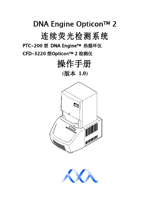
OPTICON2 操作手册 v1.0(中文版)
10-1
附录 A………………………………………………………………
A-1
附录 B………………………
B-1
附录 C
C-1
附录 D
D-1
iii
符号解释
警示:危险!在手册中出现此符号表示使用前要特别注意,同时
包含不适当操作可能造成人身伤害的意思。
警示:电击危险!此符号包含不适当操作有可能造成电击危险的
意思。
ii
目录
符号解释………………………………………………………………
iv
安全警示………………………………………………………………
iv
安全使用指南…………………………………………………………
v
电磁干扰………………………………………………………………
v
FCC 警示………………………………………………………………
如何使用这本手册
这本手册介绍了如何安全有效地操作 DNA Engine Opticon 2 连续荧光定 量检测系统:
第二章让用户了解 Opticon 2 的物理性能 第三章阐述了 Opticon 2 系统的安装和操作 第四章阐述了 Opticon 2 系统化学试剂及样品容器的匹配性 第五到八章将告诉用户如何使用Opticon MonitorTM 软件,包括如何进入 和运行程序,如何分析获得的数据 第九章告诉用户如何正确维护 Opticon 2 系统 第十章提供用户关于 Opticon 2 系统故障及维修信息
计算机特性:(为 Opticon 2 系统提供的最低配置要求)
处理器:
英特尔CeleronTM处理器,主频 800HHz
操作系统:
Windows ®NT/2000; XP
显示器:
4338 4336转速仪表使用说明书

20mA。
4
SP2
-PS- 参数修改后在退出前必须按 SP2 键,表示修改值存入
5 SP2、▽ 显示状态 退出修改,若不按 SP2、▽键 12 秒后自行返回显示状态
2.操作说明 a)n、%、f 值的查看 在显示状态下,仪表盘面的 n 灯亮、表示当前显示为转速值;按 SP2 键、%灯亮表
示当前显示为转速的%;按 SP2 键、f 灯亮表示当前显示为频率值。 b)n、%、f 最大值(百分比)的查看、清除 在显示状态下,仪表盘面 n 灯亮、显示当前转速值,按△键 Max 灯亮,此时数码
-1-
一、概述
TDS-4338 型数字转速信号测控装置是用于测控发电机级的转速、转速百分比、频 率的工业智能仪表。专为水力发电厂设计的,它以单片机及相应的外围芯片组成,智 能化程度高,性能稳定可靠。1995 年 12 月经省经委组织省级鉴定,确认产品达到国内 先进水平,而后在实践中几经改进、完善,是发电机组转速监控的优选产品。 特点:1、有七路继电器接点输出,继电器的状态分别由仪表面板七个发光管指示。
注:未带通讯接口的无“Jns-”、“1np-”、“-nSn”参数项,也就是 4、5、6 项。
-4-
c)各转速控制点(n%)的设定步骤 (表 3)
步
按下
显示
骤
按键
代码
按下 按键
出厂 数值
可调整范围:用△、▽键修改
TDS-4338
TDS-4336
1 SP2、△ -J1-
SP2
00
-(0-5)
-(0-5)
此为转速过速。
5)飞逸停机:当转速超过飞逸点后,J7 指示灯亮,且输出继电器闭合并保持。
6)飞逸清除:当转速下降到小于飞逸点时,J7 继电器仍保持其闭合状态,,此时
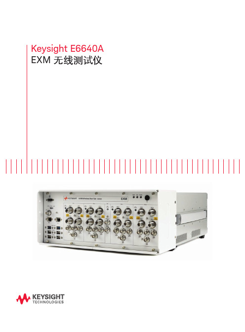
Keysight E6640A EXM 无线测试仪 用户手册说明书
Keysight E6640A EXM 无线测试仪目录从容应对当前挑战,轻松满足未来需求 (2)根据您的生产需求进行扩展. (3)加速从新产品导入到全面量产的过程. (4)以更快的速度和更强的信心推出新产品系列. (5)为大批量制造创建灵活的系统. (7)测试场景 (10)推动芯片组获得更广泛的接受 (13)丰富经验支持 (13)产品导览 (14)相关文献 (16)从容应对当前挑战,轻松满足未来需求如今在无线行业中,智能手机和平板电脑相融合的技术数量令人难以置信。
支持蜂窝和无线连通性的多天线、多制式终端正在快速发展,满足最终用户对快速数据吞吐量、通用存取和即时共享的需要。
这给正在开发和生产最新的芯片组和用户设备(UE)的制造商带来重大挑战。
成功的制造商需要使用适当的工具,以便满足日渐严格的目标和紧凑日程。
制造商能够访问最好的资源,有助于应对技术、业务和运营风险,实行谨慎的风险管理可确保成功。
当这些风险因素得到控制时,企业就能实现几个关键目标:– 快速启动试生产– 实现并优化全面量产过程– 最大限度地降低总体测试成本– 满足预算要求– 降低损耗当前,多制式、多频段终端给制造商带来了巨大的测量挑战——找到效率更高而且效果更好的测试方法是成功的关键。
在此情况下,Keysight E6640A EXM 无线测试仪沿袭了之前测试仪中的非信令和排序功能。
根据您的生产需求进行扩展EXM 是基于 PXI 标准的平台,它的体系结构可以支持并行测试功能,并提供极高的可扩展性。
EXM 测试仪获得出色灵活性的关键是其功能丰富的发射/接收模块(TRX )。
您可以自由选择一个 TRX 模块并在今后添加多达三个 TRX 模块,您也可以升级 TRX 的频率或分析带宽,这样您能够经济有效地满足当前的生产要求,在今后生产需求扩张时保护您的投资。
2-TRX3-TRX4-TRX图 1. EXM 平台能够逐步扩大您的生产能力TRX 与 TRX 之间以及 RFIO 之间的高隔离度满足了用户对测试站支持密集度不断增加的天线和器件的需要。
爱立信 MINI-LINK 6365 无线电单元 用户手册说明书

MINI-LINK 6365MINI-LINK 6000The increasing complexity of today’s and future networks requires flexible and well-integrated microwave nodes. Building an efficient microwave backhaul network with end-to-end performance in mind, requires high node capacity, compact and modular building practice, advanced packet functionality and features that are aligned and backward-compatible across different network nodes. The microwave nodes also need to be capable of handling single hops as well as advanced hub sites for larger networks. By combining different units in the MINI-LINK 6000 portfolio, all network scenarios are supported with superior performance and lowest possible cost of ownership.Ericsson is the market leader in microwave transmission and has over 40 years of microwave experience with more than 4 million radio units delivered to over 180 countries. High capacities in a compact formatThe MINI LINK 6365 is to be used in split systems together with MINI-LINK 6000 nodes. The radio connects to the node via a single coaxial cable. It comes in all traditional frequency bands 6-42 GHz and is future proof with carrier aggregation and 16k QAM support. It supports 2.5 Gbps in a very compact format. The high output power caters for the need of high capacities and high availability, providing superior network performance.World’s smallest high power radioMINI-LINK 6365 builds on the strengths of MINI-LINK 6363 and RAU2 X, the world´s most widely deployed microwave radio. MINI-LINK 6365 has the same small footprint as MINI-LINK 6363. This enables easier and faster installations as well as less wind load on towers.Ericsson ABSE-417 56 Göteborg, Sweden 287 01-FGC 101 3676 Rev B© Ericsson AB 2020Carrier aggregation – 2x 112 MHz and 2.5 GbpsMINI-LINK 6365 is a 1T1R radio supporting carrier aggregation. It can transmit two channels, up to 2x 112 MHz, in the same polarization,doubling the capacity vs MINI-LINK 6363. The channels can be adjacent or non-adjacent, for maximum utilization of available spectrum. 2x 112 MHz carrier aggregation provides a capacity of 2.5 Gbps, to support the ever-growing need for higher capacities. Carrier aggregation is available as a SW license, making it possible to double the capacity without changing the hardware.Highest modulation scheme – 16k QAMThe radio supports the highest modulation scheme in the market 16k QAM, increasing capacity by 15% vs 4k QAM and 25% vs 2k QAM.Superior system gainMINI-LINK 6365, in combination with MINI-LINK 6000 nodes, has the highest system gain in the split mount market, maintained also for higher modulations. The high system gain is crucial to enable the use of the high modulations and carrier aggregation. A high system gain means more capacity, higher availability and smaller antennas. High output power is available as a SW license, which makes it possible to step up in modulation and capacity when needed.Modular antennas and flat panel antennasMINI-LINK 6365 uses the same antenna portfolio as MINI-LINK 6363. The 0.3-1.8 m reflector antennas are modular, making them upgradeable from single to dual polarization without the need for realignment. This is done by replacing the interface only. With high focus on visual appearance and minimized size, Ericsson has created the world's smallest outdoor unit (radio+antenna) in traditional bands with a range of flat panel antennas. Since antenna performance is key to secure network performance, the flat panel antennas are guaranteed to be ETSI class 3 compliant and typically close to ETSI class 4 compliance.Scalable multi-carrier solutions, with hardware protectionA scalable upgrade path from single to multi-carrier is supported:1+0 → 2+0 → 4+0 → 8+0. Investments can be taken as the need for more capacity arises, following a pay as you grow approach. With MINI-LINK 6365, a single type of radio be can be used throughout the network. This simplifies network rollout and reduces operation costs. Transceivers in separate housings also gives better hardware protection and ensures no downtime during replacement of faulty hardware.Backward compatibilityMINI-LINK 6365 is hop compatible with MINI-LINK 6363 and MINI-LINK RAU2 X, in single carrier mode. If a radio unit needs to be upgraded, the antenna and radio cable can be reused.Ingress protectionThe radio unit can be installed in very harsh environments as it fulfills IP66 protection against dust and water.ATEX certifiedWith ATEX certification MINI-LINK 6365 can be used in potentially explosive atmospheres (Zone 2).Technical Specification MINI-LINK 6365RADIO LINKCapacity: 2.5 GbpsChannel: 7 – 112 MHzCarrier aggregation: 2x 28 – 2x 112 MHzModulation:4 QAM – 16k QAMTX power: -10 to +30 dBmFREQUENCIES 6 – 42 GHzWEIGHT 2.5 kg / 5.5 lbsDIMENSIONS (H × W × D) 179 × 197 × 79 mm (2.8 l) 7.0 × 7.8 × 3.1 in (170 in 3)POWER SUPPLY +57 VDCPOWER CONSUMPTION 24 WREFLECTOR ANTENNAS 0.2 – 3.7 m / 9 in – 12 ft HP and HPX SHP and SHPXFLAT PANEL ANTENNAS 0.1 m SHP28 – 42 GHz, 30 – 34 dBiINTEGRATEDCONFIGURATIONS 1+0, 1+1, 2+0, 4+0 and 8+0INTERFACES Coaxial (modem)Waveguide (antenna) Alignment portSTANDARDS AND RECOMMENDATIONS ETSI, ECC, FCC, IC, IEC, ITU, ATEXENVIRONMENTAL SPECIFICATIONS -45 to +60 °C / -49 to +140 °F IP66NODES MINI-LINK 6000NETWORK MANAGEMENTServiceOn Element Manager IP Transport NMSEricsson Network Manager。
HP8920A无线电综合测试仪说明书 (1)
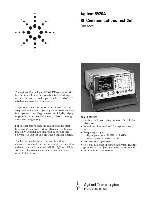
The Agilent Technologies 8920A RF communication test set is a full-featured, one-box test set designed to meet the service and repair needs of today’s RF wireless communications market.Single keystroke transmitter and receiver testing simplifies radio test. Signaling for multiple formats is supported, including tone sequential, digital pag-ing (CCITT, POCSAG, ZVEI, etc.), DTMF, trunking, and cellular signaling.For cellular phone test, the call processing inter-face emulates a base station, allowing you to auto-matically establish and maintain a cellular link between the test set and an analog cellular phone. The built-in controller allows you to automate measurements and test routines, and control exter-nal instruments. Combined with the Agilent 11807A software, it provides a self-contained, automated radio test solution.Key Features:•Intuitive call processing interface for cellular phone test•Functions of more than 20 complete instru-ments•Frequency ranges:Signal generator: 30 MHz to 1 GHzRF analyzer: 10 MHz to 1 GHz•Portable and lightweight•Optional full-span spectrum analyzer, tracking generator and adjacent channel power meter •Built-in IBASIC computerAgilent 8920ARF Communications Test SetData SheetAgilent 8920A RF Communications Test Set SpecificationsSpecifications describe the instrument’s warranted performance and are valid over the entire operating/environmental range unless otherwise noted.Supplemental Characteristics are intended to provide additional information useful in applying the instrument by giving typical, but non-warranted performance parameters. These characteristics are shown in italics or labeled as “typical,” “usable to,” or “nominal.”Signal Generator SpecificationsRF FrequencyFrequency Range:Standard: 30 MHz to 1 GHzOption 055:250 kHz to 1 GHzAccuracy and Stability:Same as reference oscillator ±0.015 Hz Reference Oscillator SpecificationsTCXO(Agilent 8920A standard)Temperature:1 ppm (0 to +55 °C)Aging:<2 ppm/yearWarm-Up time:<30 sec. to be ±2 ppm of final freq. Supplemental CharacteristicsSwitching Speed: <150 ms to within 100 Hz of the carrier frequencyMinimum Resolution:1 HzOutputRF IN/OUT ConnectorLevel Accuracy:±1.8 db (level ≥–127 dBm),Typically ±1.0 dB for all levelsLevel RangeStandard:Level Range:–137 to –20.5 dBm into 50 ΩReverse Power:60 watts continuous,100 watts for 10 seconds/minuteWith Option 007:Level Range:–137 to –6.5 dBm into 50 ΩReverse Power:2.4 watts continuous,4 watts for 10 seconds/minuteWith Option 008:Level Range:–137 to –10.5 dBm into 50 ΩReverse Power:6 watts continuous,10 watts for 10 seconds/minuteWith Option 016:Level Range:–137 to –22.5 dBm into 50 ΩReverse Power:100 watts continuous,125 watts for 10 seconds/minute Option 055:Level Range:–137 to –19 dBm into 50 ΩReverse Power:60 watts continuous,100 watts for 10 seconds/minuteWith Option 007:Level Range:–137 to –5 dBm into 50 ΩReverse Power:2.4 watts continuous,4 watts for 10 seconds/minuteWith Option 008:Level Range:–137 to –9 dBm into 50 ΩReverse Power:6 watts continuous,10 watts for 10 seconds/minuteWith Option 016:Level Range:–137 to –21 dBm into 50 ΩReverse Power:100 watts continuous,125 watts for 10 seconds/minuteDUPLEX OUT ConnectorStandard:Level Accuracy:±1.5 dB, typically ±1.0 dB for all levelsLevel Range:–127 to +5 dBm into 50 ΩReverse Power:200 mW maxOption 055:Level Range:–127 to +7 dBm into 50 ΩSWR:RF In/Out:<1.5:1Duplex Out:<2.0:1 (level <–4 dBm)Supplemental CharacteristicsMinimum Resolution:0.1 dBSpectral PuritySpurious Signals:For specified output levels at DUPLEX OUT port or specified output level at RF IN/OUT port.Option DUPLEX OUT RF IN/OUT Standard≤–2.5 dBm≤–26.5 dBm007≤–2.5 dBm≤–12.5 dBm007 with Opt. 055≤–1.0 dBm≤–11.0 dBm008≤–2.5 dBm≤–16.5 dBm008 with Opt. 055≤–1.0 dBm≤–15.0 dBm016≤–2.5 dBm≤–28.5 dBm016 with Opt. 055≤–1.0 dBm≤–27.0 dBm055≤–1.0 dBm≤–25.0 dBmHarmonics:<–30 dBcNon-Harmonic Spurious:<–60 dBc (at >5 kHz from carrier) Residual FM (rms, CCITT):Frequency Range8920A Standard8920A Opt. 050 250 kHz ≤f c<249 MHz<20 Hz<7 Hz249 MHz ≤f c<501 MHz<10 Hz<4 Hz501 MHz ≤f c≤1000 MHz<20 Hz<7 Hz2SSB Phase Noise: (For >20 kHz offsets at 1 GHz)8920A <–110 dBc/Hz8920A Opt. 050 <–116 dBc/HzFMFM Deviation Maximum (For rates >25 Hz)Standard and Options 007, 008, 016:100 kHz for f c from 30 MHz to <249 MHz50 kHz for f c from 249 MHz to <501 MHz100 kHz for f c from 501 MHz to 1000 MHzOption 055:100 kHz for f c from 0.25 MHz to <249 MHz50 kHz for f c from 249 MHz to <501 MHz100 kHz for f c from 501 MHz to 1000 MHzFM Rate (1 kHz reference)Internal:DC to 25 kHz (1 dB BW)External:AC Coupled: 20 Hz to 75 kHz (typically 3 dB BW)DC Coupled: DC to 75 kHz (typically 3 dB BW)FM Accuracy:(1 kHz rate)≤10 kHz dev: ±7.5% (3.5%*) of setting ±50 Hz>10 kHz dev: ±7.5% (3.5%*) of setting ±500 HzFM Distortion:(THD + Noise, in a 0.3 to 3 kHz BW)<1% (0.5 %*) at > 4 kHz deviation and 1 kHz rateCenter Frequency Accuracy in DC FM Mode:(External source impedance <1 kΩ) ±500 Hz(after DC FM zero), typically ±50 HzSupplemental CharacteristicsExternal Modulation Input Impedance: 600 Ωnominal Resolution: 50 Hz for <10 kHz deviation, 500 Hz for >10 kHz deviationAMStandard:Frequency Range:30 MHz to 1 GHzAM Depth:0 to 90% (usable to 99%) for DUPLEX OUT level ≤–2.5 dBm or RF IN/OUT level ≤–26.5dBm; 0 to 70% (usable to 90%*)Option 055:Frequency Range:1.5 MHz to 1 GHz (usable to 250kHz)AM Depth:0 to 90% (usable to 99%) for DUPLEX OUT level ≤+1 dBm or RF IN/OUT level ≤–27dBm; 0 to 70% (usable to 90%*)AM Rate:20 Hz to 25 kHz (3 dB BW)AM Accuracy:(1 kHz rate)≤10% AM: ±5% of setting ±1.0% AM>10% AM: ±5% of setting ±1.5% AMAM Distortion:(THD+Noise 0.3 to 3 kHz BW)<2% at 1 kHz rate, <30% AM<3% at 1 kHz rate, ≤90% AM External Mod. Input Impedance:600 ΩnominalResidual AM: <0.1% in a 50 Hz to 15 kHz BWResolution: 0.05% AM from 0 to 10% AM, 0.5% AM from 10 to 100% AMAudio Source Specifications(Applicable to both internal sources)FrequencyRange:dc to 25 kHzAccuracy:0.025% of settingSupplemental CharacteristicsMinimum Resolution: 0.1 HzOutput LevelRange:0.1 mV to 4 VrmsMaximum Output Current:20 mA peakOutput Impedance:<1 Ω(1 kHz)Accuracy:±2% of setting plus resolutionResidual Distortion:0.125%(THD plus noise, for amplitudes >200 mVrms), for tones 20 Hz to 25 kHz measured in an 80 kHz BWSupplemental CharacteristicsResolution:Level <0.01V: ±50 µVLevel <0.1V: ±0.5 mVLevel <1V: ±5 mVLevel <10V: ±50 mVOffset in DC Coupled Mode: <50 mVRF Analyzer MeasurementsRF Frequency MeasurementsMeasurement Range:Standard:30 MHz to 1 GHzOption 055:400 kHz to 1 GHzLevel Range:RF In/Out:Standard:1 mW to 60 W continuous 100 W for10 seconds/minuteOption 007:40 mW to 6 W continuous 4 W for10 seconds/minuteOption 008:0.1 mW to 6 W continuous 10 W for10 seconds/minuteOption 016:1.6 mW to 100 W continuous 150 W for10 seconds/minuteANT IN:–36 dBm to +20 dBmAccuracy:±1 Hz plus timebase accuracy3Minimum Frequency Resolution: 1 HzRF Power MeasurementsFrequency Range:Standard:30 MHz to 1 GHzOption 055:400 kHz to 1 GHzSWR:<1.5:1 for standard and all optionsRF IN/OUT Measurement Range:Standard:1 mW to 60 W continuous or to 100 W for10 sec/minuteAccuracy:±10% of reading ±1 mWOption 007:40 µW to 2.4 W continuous 4 W for10 seconds/minuteAccuracy:±10% of reading ±40 µWOption 008:0.1 mW to 6 W continuous 10 W for10 seconds/minuteAccuracy:±10% of reading ±0.1 mWOption 016:1.6 mW to 100 W continuous 125 W for10 seconds/minuteAccuracy:±10% of reading ±1 mWSupplemental CharacteristicsResolution: P >10 W: 10 mW, P <10 W: 1 mW; P <100 mW: 0.1 mW, P <10 mW: 0.01 mWFM MeasurementFrequency Range:Standard:10 MHz to 1 GHzOption 055:5 MHz to 1 GHz (Usable to 400 kHz) Deviation:20 Hz to 75 kHzSensitivity:2 µV (15 kHz IF BW, high sensitivity mode, 0.3 to 3 kHz BW, 12 SINAD, fc >10 MHz) Typically:<1 µVAccuracy:±4% of reading plus residual FM and noise contribution (20 Hz to 25 kHz rates, deviation ≤25kHz)Bandwidth (3 dB):2 Hz to 70 kHz (DC FM measurements also available)Input Level Range for Specified Accuracy:Standard:–50 dBm to +14 dBm at ANT IN –18 to +50 dBm at RF IN/OUT (0.16 mW to 100 W*)Option 007:–32 to +36 dBm at RF IN/OUT (0.63 µW to 4 W*) Option 008:–28 to +40 dBm at RF IN/OUT (1.58 µW to 10 W*) Option 016: –16 to +51 dBm at RF IN/OUT (0.25 µW to 125 W*) *Note: The accuracy shown is for the complete range of power. The maximum power levels shown are only usable for 10sec/min.Residual FM and Noise:20 Hz (0.3 to 3 kHz, rms), <7Hz (with Agilent 8920A Opt 050)Resolution: 1 Hz, f <10 kHz; 10 Hz, f ≥10 kHzAM MeasurementFrequency Range:10 MHz to 1 GHz (usable to 400 kHz) Depth:0 to 95%Accuracy:±5% of reading ±1.5% AM (50 Hz to 10 kHz rates, mod-ulation ≤80%)THD + Noise:<2% rms for modulation ≤80% AM (at 1 kHz rate in a 0.3 to 3 kHz BW)Input Level Range for Specified Accuracy:Standard:–50 dBm to +14 dBm at ANT IN –18 to +50 dBm at RF IN/OUT (0.16 mW to 100 W*)Option 007:–32 to +36 dBm at RF IN/OUT (0.63 µW to 4 W*) Option 008:–28 to +40 dBm at RF IN/OUT (1.58 µW to 10 W*) Option 016:–16 to +51 dBm at RF IN/OUT (0.25 µW to 125 W*) *Note: The accuracy shown is for the complete range of power. The maximum power levels shown are only usable for 10 sec/min. Residual AM:<0.2% in a 0.3 to 3 kHz bwSupplemental CharacteristicsResolution: 0.1%SSB MeasurementFrequency Range:Standard:10 MHz to 1 GHzOption 055:400 kHz to 1 GHzBandwidth (3 dB):20 Hz to 70 HzDistortion and Noise:<3% (at 1 kHz rate in a 0.3 to 3 kHz BW)AF Analyzer SpecificationsFrequency MeasurementMeasurement Range:20 Hz to 400 kHzAccuracy:±0.02% plus resolution plus timebase accuracy External Input:20 mV to 30 VrmsSupplemental CharacteristicsResolution:0.01 Hz, f <10 kHz; 0.1 Hz, f <100 kHz; and 1 Hz forf ≥100 kHzAC Voltage MeasurementMeasurement Range:0 to 30 VrmsAccuracy:±3% of reading (20 Hz to 15 kHz, inputs >1 mV) Residual Noise:150 µV (15 kHz bandwidth)43 dB Bandwidth: Typically 2 Hz to 100 kHzNominal Input Impedance: Switchable between1 MW in parallel with 95 pF or 600 ΩfloatingMinimum Resolution:4 digits for inputs ≥100 mV; three digits for inputs <100 mVDC Voltage MeasurementVoltage Range:100 mV to 42 VAccuracy:±1% of reading plus DC offsetDC Offset:±45 mVSupplemental CharacteristicsResolution:1 mVDistortion MeasurementFundamental Frequency:1 kHz ±5 HzOption 019 Frequency Range:0.3 to 10 kHz ±5%Input Level Range:30 mV to 30 VrmsDisplay Range:0.1% to 100%Accuracy:±1 dB (0.5 to 100% distortion) for tones from 300 to 1500 Hz measured with the 15 kHz LPF±1.5 dB (1.5 to 100% distortion) for tones from 300 Hz to 10 kHz measured with the >99 kHz LPF)Residual THD + Noise:–60 dBc or 150 µV whichever is greater, for tones from 300 to 1500 Hz measured with the 15 kHz LPF–57 dBc or 450 µV, whichever is greater, for tones from 300 Hz to 10 kHz measured with >99 kHz LPF)Supplemental CharacteristicsResolution: 0.1% distortionSINAD MeasurementFundamental Frequency:1 kHz ±5 HzOption 019 Frequency Range:0.3 to 10 kHz ±5%Input Level Range:30 mV to 30 VrmsDisplay Range:0 to 60 dBAccuracy:±1 dB (0 to 46 dB SINAD) for tones from 300 to 1500 Hz measured with the 15 kHz LPF±1.5 dB (0 to 36 dB SINAD) for tones from 300 Hz to 10 kHz meas-ured with the >99 kHz LPFResidual THD + Noise:–60 dBc or 150 mV, whichever is greater, for tones from 300 to 1500 Hz measured with the 15 kHz LPF–57 dBc or 450 mV, whichever is greater, for tones from 300 Hz to 10 kHz measured with >99 kHz LPF Resolution: 0.01 dBAudio FiltersStandard:<20 Hz HPF, 50 Hz HPF, 300 Hz HPF 300 Hz LPF, 3 kHz LPF, 15 kHz LPF, >99 kHz LPF, and 750 µsec de-emphasisFixed Notch:1 kHz, (Agilent 8920A standard)Variable Notch:300 Hz to 10 kHz (Option 019)Optional:C-Message, CCITT, 400 Hz HPF, 4 kHz BPF, 6 kHz BPF (see options)Audio Detectors: RMS, RMSxSQRT2, Pk+, Pk–, Pk+hold, Pk–hold, Pk±/2, Pk±/2 hold, Pk±max and Pk±max hold Oscilloscope SpecificationsFrequency Range:2 Hz to 50 kHz (3 dB BW)Scale/Division:10 mV to 10 VAmplitude Accuracy:±1.5% of reading ±0.1 division(20 Hz to 10 kHz)Time/Division:1 µsec to 200 msecSupplemental Characteristics3 dB Bandwidth: Typically >100 kHzInternal DC Offset: ≤0.1 div (≥50 µV/div sensitivity)Input and Output SpecificationsDigital Interface PortRS-232 port:2 wayConnector: RJ-11connector (6 pins; 2 addressable serial ports with single connector; Agilent 8920A rear panel)Baud Rates:300/600/1200/2400/4800/9600/19200Reference In PortConnector:BNC female (8920A rear panel)Input frequency:1/2/5/10 MHzInput Level Range:>0.15 VrmsReference Out PortConnector:BNC female (8920A rear panel)Output Frequency:10 MHzOutput Level: >0.5 VrmsStandard User Memory, RAMApproximately 1 Mbyte of RAM is available for nonvolatilesave/recall of settings. This typically will allow you to save >1000 sets of instrument settings; depending on the type of information saved.5Option SpecificationsOption 001: High Stability TimebaseOCXO: (Oven controlled crystal oscillator)Temperature:0.05 ppm (0 to +55 °C)Aging:<0.5 pm/year (<1 ppm in first year)Warm-up Time:<15 minutes to be within ±0.1 ppm of finalfrequencySupplemental CharacteristicsRear Panel BNC Connectors:Input Frequency: 1, 2, 5, and 10 MHzInput Level: >0.15 VrmsOutput Frequency: 10 MHzOutput Level: >0.5 VrmsOption 004: Tone/Digital SignallingCapability for generating and analyzing the formats listed here: CDCSS, DTMF, 1-TONE, 2-TONE, 5/6 TONE SEQUENTIAL, RPC1, POCSAG, EIA, CCITT, CCIR, ZVEI, DZVEI, GOLAY, EEA, NMT-450, NMT-900, LTR, AMPS/EAMPS/NAMPS, TACS/ETACS,JTACS/NTACS, EDACS, and MPT 1327.A General Purpose function generator with the following wave forms included:Sine, square, triangle, ramp, Gaussian white noise, uniform white noiseFrequency Range/Level:Same as audio sourceOption 007 and Low-Level RF Power MeasurementsOption 007 removes a 14 dB attenuator at the RF IN/OUT port allowing lower-level, higher sensitivity measurements. This option reduces the maximum continuous input power of the Agilent 8920A from 60 watts to 2.4 watts. Specifications for Option 007 are included in the appropriate sections of: Signal Generator out-put, RF Analyzer, Frequency and Power Measurement Ranges, FM and AM Measurement Input Level Ranges.Option 008 Cellular Mobile RF Power Measurement RangeOption 008 removes 10 dB attenuation at the RF IN/OUT port allowing lower-level, higher sensitivity measurements specifically for the range of cellular telephones testing. This option reduces the maximum continuous input power of the 8920A from 60 watts to 6 watts. Specifications for Option 008 are included in the appro-priate sections of: Signal generator output, RF analyzer, frequency and power measurement ranges, FM and AM measurement input level ranges.Option 010: 400 Hz High Pass FilterOption 011: CCITT Weighting FilterOption 012: 4 kHz Bandpass Filter Option 013: C-Message Weighted FilterOption 014: 6 kHz Bandpass FilterOption 016 High-Level RF Power Measurements Option 016 for the 8920A supports high-power transmitter meas-urement applications. Option 016 can only be ordered on a new instrument at the time of purchase. Option 016 can only be installed at the factory.Option 019: Variable Notch FilterFrequency Range:300 Hz to 10 kHzNotch Depth:>60 dBNotch Width:Typically ±5%Option 020: Radio Interface CardThe Option 020 for the 8920A is a built-in radio interface card for automating module and radio board test. It contains 16 parallel data lines, two interrupts, and brings the audio in/out lines and a relay closure out from the MIC/ACC connector on the front panel. These are controlled by the 8920A BASIC control language. Line Levels:5 volts or 12 voltsOption 050: Improved Residual FM Performance Includes high stability timebase (Option 001), improved residual FM performance.Option 102: Spectrum Analyzer with Tracking Generator and ACPFrequency Range:10 MHz to 1 GHzFrequency Span/Resolution Bandwidth:(coupled)Span Bandwidth<50 kHz300 Hz<200 kHz 1 kHz<1.5 MHz 3 kHz<18 MHz30 kHz>18 MHz300 kHz, plus full span capabilityDisplay:Log with 1, 2, and 10 dB/divDisplay Range:80 dBReference Level Range:+50 to –50 dBmResidual Responses:<–70 dBm (no input signal, 0 dB attenuation)Image Rejection:>50 dBmSupplemental CharacteristicsNon-Harmonic Spurious Responses: >70 dB down (for input sig-nals ≤–30 dBm)6Level Accuracy: ±2.5 dBDisplayed Average Noise Level: <–114 dBm for <50 kHz spans Log Scale Linearity: ±2 dB (for input levels ≤–30 dBm and/or 60 dB rangeTracking Generator (In Option 102)Frequency Range:30 MHz to 1 GHzFrequency Offset:Frequency span endpoints ±frequency offset cannot be <30 MHz or ≥1 GHzOutput Level Range:Same as signal generatorSweep Modes:Normal and invertedAdjacent Channel Power (In Option 102) Relative Measurements:Level Range:Antenna IN:–40 dBm to +20 dBmRF/Input:0.16 mW (–8 dBm) to 60 W (47.8 dBm)continuous; or up to 100 mW (50 dBm) for 10 sec/min Dynamic Range:Typical values for channel offsetsChannel Offset Res. BW Dyn. Range12.5 kHz8.5 kHz–65 dBc20 kHz14 kHz–68 dBc25 kHz16 kHz–68 dBc30 kHz16 kHz–68 dBc60 kHz30 kHz–65 dBcRelative Accuracy:±2 dBAbsolute Level Measurements:Level:(Results of absolute power in watts or dBm are met by adding the ACP ratio from the SA to the carrier power from the input section RF power detector).Level Range:Antenna:N/ARF/Input:1 mW (0 dBm) to 60 W (47.8 dBm) continuous; or up to 100 W (50 dBm) for 10 sec/minDynamic Range:Typical values for channel offsetsChannel Offset Res. BW Dyn. Range12.5 kHz 8.5 kHz–65 dBc20 kHz 14 kHz–68 dBc25 kHz 16 kHz–68 dBc30 kHz 16 kHz–68 dBc60 kHz 30 kHz–65 dBcAbsolute Accuracy:RF power measurement accuracy found in the RF Analyzer section and ACP relative accuracy of ±2 dB Option 103: DC Current Sensing and I/O:GPIB/RS-232/Parallel (Centronics)DC Current MeterMeasurement Range:0 to 10 A (usable to 20 A)Accuracy:The greater of ±10% of reading after zeroing or 30 mA (levels >100 mA)Remote ProgrammingGPIB:Agilent’s implementation of IEEE Standard 488.2 Functions Implemented:SH1, AH1, T6, L4, SR1, RL1, LE0, TE0, PP0, DC1, DT1, C4, C11, E2RS-232:Two serial ports through RJ-11 connector used for serial data in and outBaud Rates:150, 300, 600, 1200, 2400, 4800, 9600 and 19200 Hz Parallel (Centronics) Connector: A standard 25-pin, sub-min D female connector with right-angle adapter is includedNote: Retrofittable only for 8920A units with serial prefix numbers of 3501 or greaterGeneral Specifications8920A Dimensions:H ϫW ϫD in inches and (mm): 7.5 H ϫ13 W ϫ19 D (188 H ϫ330 W ϫ456 D)8920A Weight:(fully optioned) 37 lbs. (16.8 kgs)8920A Power:AC: 100 V to 240 V, 48 to 440 Hz, nominally 80 wattsDC: 11 to 28 V, nominally 120 watts8920D Power:AC: 100 V to 240 V ±10%, 48 Hz to 440 Hz, nominally 100 watts CRT Size:7 ϫ10 cmOperating Temperature:0 to +55 °CStorage Temperature:–55 to +75 °CCalibration Interval:Two yearsSupplemental CharacteristicsLeakage: At signal generator output frequency and level <–40 dBm, typical leakage is <0.5 µV induced in a resonant dipole antenna one inch from any surface except the rear panel. Spurious leakage levels are typically <1 µV in a resonant dipole antenna.7H i g h S t a b i l i t y T i m e b a s eS i g n a l i n gL o w -P o w e r M e a s u r e m e n tC e l l u l a r M S R F P o w e r R a n g e400 H z H i g h -P a s s F i l t e rC C I T T W e i g h t i n g F i l t e r4 k H z B a n d p a s s F i l t e rC -M e s s a g e W e i g h t i n g F i l t e r6 k H z B a n d p a s s F i l t e rV a r i a b l e F r e q u e n c y F i l t e rM e c h a n i c a l A t t e n u a t o rS p e c r u m A n a l y ./T r a c k i n g G e nG P I B /R S -232 P a r a l l e l11807A R a d i o T e s t S o f t w a r e (O p t i o n s )Automated FM Radio Test 3O O O O O O 001Automated φm Radio Test 3O OOOO 002Automated AM Radio Test OO003Testing Communications Bandwidths <30 MHz XCordless Phone Test 3OOXOFrequency Scanning O Cable Fault Location 2X O Field Strength Measurement XO 100Intermodulation Prod. Cal.O Save/Recall Procedure OLTR Trunked Radio Test 3(Includes FM radio tests)O X X O O O 010EDACS Trunked Radio Test 3(Includes FM radio tests)O X O O O O 011MPT 1327 Trunked Radio Test 3O X OO OO 012AMPS/EAMPS/NAMPS O X OO O O 004TACS/ETACS O X O OO O 005NMT 450/900O X O OO O 006JTACS/NTACSOXOOO007Configuration InformationX = Required Option O = Recommended Option 8920A Options00100400710081010011012013014019055102103M e a s u r i n g C a p a b i l i t yT r u n k e d R a d i oC e l l u l a r P h o n e T e s t1.Options 007 and 008 reduce the maximum input power of the 8920A from 60 watts to2.4 and 6 watts respectively. Option 008 is recommended for applications where the 8920A is used for cellular phone test only.2.Requires an external power divider and 50 ohm load to make measurement.3.Testing frequencies below 30 MHz will require ordering Option 055 (400 kHz to 1 GHz).By internet, phone, or fax, get assistance with all your test and measurement needs.Online Assistance/find/assistProduct specifications and descriptions in this document subject to change without notice.Copyright © 1994, 2000 Agilent Technologies Printed in U.S.A. 10/005968-5385EFor more information, visit our website at:/find/8920support/。
CMS50 CMS52 无线电测试仪说明书

~ Applications
• Radiocom Tests • Portable and Handhr.ld Mobile • Phone Test
ForyouJ'local n,!;lrollix J'I'j}),(!I'oJlllllil'o 80(! II", /i"
ill th" hac!; of this r:(Jlok'M or oliisido till" U.S. (',,/I: '.s. 1~S03-(i27-Jfl33. iI1sirl" the 1 mil: 1-1J()()~42(i-2:!O().
Modulation frequency range (CMS52): f <8 MHz, DC to 10kHz; f ~8 MHz, DC to 20 kHz. (CMS50): 15 Hz to 10kHz. kB MHz.