Conceptual Design
建筑设计英语

Acrylic[ə'krɪlɪk]亚克力Construction: 指建造的那个建筑, construct对应的名词,如“建筑工程”construction project Architecture: 指具体的建筑物,风格Building: 一般指的是某幢建筑物。
Stage1: Architectural Conceptual design建筑概念设计●Plan 平面图●Reference pictures 参考图片/风格意向图●Presentation document汇报文件Stage2: Architectural Schematic design方案设计●Renders效果图●方案: Elevation立面图, Section剖面图●Construction design 施工设计●Presentation document汇报文件Stage3: Interior Conceptual design室内概念设计●Plan 平面图●Reference pictures 参考图片/风格意向图●Presentation document汇报文件Stage4: Interior Schematic design方案设计●Renders效果图●方案: Elevation立面图, Section剖面图●Construction design 施工设计●Presentation document汇报文件plot ratio/site ratio/floor area ratio(FAR) 容积率:Gross Floor Area总建筑面积: Total covered area on all floors of all buildings on a certain plot area of the plot 建筑用地面积: The size of the piece of land upon which it is builtFloor area ratio = (Gross Floor Area) / (area of the plot) 地上总建筑面积÷建筑用地面积Parcel 地块single-story building 单层建筑multi-story building 多层建筑Schematic design方案设计Site location 场地位置Architectural style建筑风格Analysis of position区位分析 analysis of existing circumstance现状分析analysis of function功能分析analysis of traffic/circulation/streamline交通/流线分析 vehicle circulation车型流线carriageway车道drop off落客点analysis of sunshine日照分析analysis of landscape景观分析landscape sight/view/vision景观视线analysis of space sequence空间序列分析philosophy of design设计理念bubble diagram气泡图architecture conception建筑构思architectural creation建筑创作architectural sketch建筑草图layout建筑布局perspective透视图hand drawing手绘效果图 a birdˊs-eye view鸟瞰图 façade 建筑物正面Preliminary design初步设计Legend图例cover封面content内容design explanation设计说明general layout/master plan/site plan总平面图first floor plan一层平面ground floor plan基础平面图typical floor plan标准层平面图basement plan地下室平面图(B1)first basement floor负一层(G1)garage车库 roof plan屋顶平面图elevation立面section剖面enlarged preliminary design扩大初步设计Licensed architect注册建筑师electrical engineer电机工程师licensed structural engineer注册结构工程师plant engineer设备工程师mechanical engineer机械工程师landscape architect景观设计师licensed planner注册规划师plot plan engineer总图工程师project budget工程预算air-conditioning system空调系统heating and ventilation供暖与通风water supply and drainage给水与排水structure design结构设计acoustic design声学设计lighting/illuminated design照明设计indoor environment design室内环境设计Construction drawing design施工图设计Full-size drawing/Details drawing详图、大样图building code建筑规范working drawing and the specification施工图与施工说明书Technical and economic index技术经济指标Construction site建筑地基boundary line of roads道路红线boundary line of land/property line用地红线/建筑红线building line建筑控制线building density/building coverage ratio建筑密度/建筑密度率greening rate/ratio of green space绿地率Theory理论Eclecticism折衷主义 functionalism功能主义post-modernism后现代主义minimalism极简主义deconstruction/deconstructivism解构主义Italian Renaissance意大利文艺复兴green building绿色建筑Doric order多立克柱式 Ionic order爱奥尼柱式Corinthian order科斯林柱式Gothic Revival哥特复兴greek temple希腊神庙Triumphai arch凯旋门住宅专业词汇总结Sale center售楼中心/售楼部Villahouse/detached house独栋别墅semi-detached house双排别墅row house连排别墅townhouse联体别墅high-grade residential高档住宅duplex apartment跃层住宅tall building of apartment单元式高层住宅apartment of towerbuilding塔式高层住宅gallery tall of apartment通廊式高层住宅houseing cluster/group住宅组团residential community居住区residential density居住密度low-rise medium-density cluster housing低层中密度住宅群business-living building商住楼multiple-use building综合楼multiple-use high-rise building多功能高层住宅dwelling size套型habitable space居住空间bedroom卧室living room起居室family room家庭活动室kitchen厨房bathroom卫生间 balcony阳台terrace露台,平台ramp坡道passage过道gallery(corridor gallery)走廊overhanging corridor挑廊eaves gallery檐廊cloister回廊bridge way架空走廊semi-basement半地下室empty space(open floor)架空层refuge storey避难层mechanical floor设备层cabinet壁柜wall-hung cupboard吊柜view room眺望间overhang骑楼arcade过街楼stair step楼梯踏步stair well楼梯井stair landing楼梯平台stair railing楼梯栏杆envelop enclosure围护结构enclosing curtain wall围护性幕墙decorative faced curtain wall装饰幕墙French windows落地橱窗dormant window天窗dormer window老虎窗bay window凸窗/飘窗sash-window上下推拉窗eaves and gable屋檐与山墙window-blinds百叶窗parapet女儿墙/矮墙plinth勒脚/柱基canopy雨篷masonry structure砖石/砖混结构frame structure框架结构steel-frame structure钢框架结构frame-shear wall structure框架-剪力墙结构megastructure巨型结构bearing wall承重墙bearing strength承载力concrete beam混凝土梁concrete shell混凝土薄壳reinforced concrete slab钢筋混凝土楼板reinforced concrete column钢筋混凝土柱子deformation joint变形缝duration of fire resistance耐火极限safety exit安全出口hang wall挡烟垂壁suspended ceiling吊顶pipe shaft管道井smoke uptake/flue烟道air relief shaft通风道motor repair shop修车库parking area停车场under ground garage地下汽车库high rise garage高层汽车库mechanical and stereoscopic garage机械式立体车库compound garage复式汽车库Minimumturn radius of car汽车最小转弯半径规划Town and county planning(urban and rural planning)城乡规划city and regional planning城市与区域规划urban planning law of PRC中华人民共和国城市规划法城市发展战略层面: comprehensive planning/master plan城市总体规划landuse planning土地利用总体规划建筑控制引导层面:Detailed plan详细规划regulatory plan控制性详细规划site plan修建性详细规划Urban land城市用地R residential land居住用地黄色C pubic facilities公共设施用地红(commercial:商业) M industrial land工业用地熟褐(manufacture:制造) W warehouse land仓储用地紫T intercity transportation land对外交通用地中灰S roads and squares道路广场用地留白U municipal utilities市政公用设施用地蓝灰G green space绿地中草绿D specially-designed land特殊用地深草地色E water and miscellaneous水域和其他城市分区规划:city/district planning城市规模:city size城市发展模式:urban development pattern城市用地评价:urban landuse evaluation城市用地平衡:urban landuse balance城市总体布局:urban(city) layout城市结构:urban structure城市形态:urban morphologyIndustrial/commercial/residential/warehouse/institutes and college/central business/mixed-use district工业/商业/居住/仓储/文教中心/商务/综合区scenic zone风景区公共设施分布:utility distribution快速路:express way步行街:pedestrian street城市给水系统:water supply system城市排水系统:sewerage system城市供电系统:power supply system城市供暖系统:district heating system城市燃气系统:gas supply system城市通信系统:communication system城市绿地系统:urban green space system绿带:green belt防护绿地:green buffer城市生态系统:city ecosystem城市生态平衡:balance of city ecosystem城市环境质量:city environmental quality城市环境评价:city environment assessment可持续发展:sustainable development。
方案设计工程师英文缩写

方案设计工程师英文缩写1. IntroductionAs a conceptual design and engineering team, our primary goal is to define the project "XXX" accurately and comprehensively. To accomplish this, we will follow a systematic and methodical approach, starting from the initial ideation phase and progressing through all stages of the project lifecycle. Our team comprises experienced professionals with a diverse set of skills and expertise, making us well-equipped to handle the complexities inherent in this project.2. Project OverviewThe project "XXX" aims to [provide a brief description of the project, including its objectives, scope, and deliverables]. This project is of [high] importance to our organization, and its successful completion will [significantly impact our operational efficiency, customer satisfaction, or overall performance].3. Concepts and IdeationIn the initial phase, our team will engage in brainstorming sessions and idea generation activities to explore various conceptual alternatives for the project. We will consider factors such as feasibility, cost-effectiveness, and environmental impact to develop a comprehensive list of potential concepts. Additionally, we will seek input from stakeholders and subject matter experts to ensure the inclusivity of our ideation process.4. Technical Feasibility AssessmentOnce we have identified a range of conceptual alternatives, we will conduct a comprehensive technical feasibility assessment for each one. This assessment will involve evaluating the viability of each concept in terms of its engineering requirements, material availability, and compatibility with existing infrastructure. We will collaborate with relevant technical experts and conduct thorough research to gather necessary data for this phase.5. Conceptual Design DevelopmentBased on the outcomes of the technical feasibility assessment, our team will proceed to develop detailed conceptual designs for the project. These designs will outline the core architectural and engineering features of the project and provide a basis for further development. Throughout this phase, we will prioritize functionality, sustainability, and safety in our designs, ensuring that they align with industry standards and best practices. 6. Cost Estimation and Risk AnalysisConcurrently with the conceptual design development, we will also perform cost estimation and risk analysis activities. Cost estimation will entail a comprehensive assessment of the financial implications associated with each conceptual design, including construction,materials, and operational expenses. Risk analysis will involve identifying and mitigating potential risks and uncertainties that could impact the project's successful implementation.7. Stakeholder Engagement and FeedbackOur team recognizes the importance of stakeholder engagement and feedback in the conceptual design and engineering process. We will actively seek input from relevant stakeholders, including end-users, management, and regulatory bodies, to ensure that our designs align with their expectations and requirements. Feedback will be incorporated into our designs iteratively, fostering a collaborative and inclusive approach to project development.8. Environmental Impact AssessmentAs part of our commitment to sustainable and responsible engineering practices, we will conduct an environmental impact assessment for each conceptual design. This assessment will evaluate the potential environmental effects of the project, such as carbon emissions, waste generation, and ecological disruption, and propose mitigation measures to minimize these impacts.9. Concept Selection and RefinementFollowing the completion of the above activities, our team will move towards the selection of the most feasible and effective conceptual design for the project. This selection will be based on a comprehensive evaluation of technical, financial, and environmental factors, as well as stakeholder input. The selected concept will then undergo further refinement and optimization to enhance its performance and practicality.10. DeliverablesThe deliverables of our conceptual design and engineering process will include:- A comprehensive report documenting the conceptual alternatives, technical feasibility, cost estimation, risk analysis, stakeholder feedback, and environmental impact assessment.- Detailed conceptual designs for the selected project concept, including architectural drawings, engineering specifications, and material requirements.- Recommendations for further development and implementation of the selected concept, along with a roadmap for the next phases of the project.11. ConclusionOur conceptual design and engineering approach for the project "XXX" is rooted in a commitment to excellence, innovation, and sustainability. By following a structured and systematic process, we aim to develop a conceptual design that not only meets the project's objectives but also aligns with our organization's values and long-term vision. We areconfident that our multidisciplinary team, coupled with our methodical approach, will result in a successful and impactful outcome for this project.。
Design Engineer and Design Methodology——设计工程师与设计方法中英文对照
Design Engineer and Design Methodology——设计工程师与设计方法1 What Makes a Good Design Engineer ? Is design an art form only to be practiced by those gifted with its talents, or is it a regimented discipline that can be learned? Virtually everything that humans do involves altering the environment around us, which is essentially what design is all about; thus every individual possesses the ability to design to some extent. While there are few Mozart’s in the history of the world, there are numerous musicians who play his music and enable us all to enjoy it. Each person must identify the area in which he feels promise, and must do the best job he can. It is true there is only one queen been in a hive, but without the workers even the queen cannot survive. In other words, be careful of your ego and always strive to improve your abilities.2 It is very difficult to teach people how to become creative design engineers because everyone thinks differently. There are often no clear solutions to a problem. Historical knowledge can also often be a powerful tool to help demonstrate how creative ideas are formed; unfortunately, a discussion of the history of machine tool development is beyond the scope of this book. Systematic methods of analysis and synthesis can be formulated to aid in development of ideas; however, these methods have often been blamed for stifling creativity. A good design engineer often uses systematic methods of analysis and synthesis in order to help evaluate wild and crazy conceptual ideas generated during the initial creative phase of problem solving.3 How can creativity be stimulated and enhanced ? Perhaps if this question could be answered with an equation, a computer program could be written that could design anything. Good design engineers usually think in terms of pictures instead of equations or if then else logic. Often, it seems as if daydreams are an inner manifestation of the creative urge within all individuals. The task of the design engineer, therefore, is to install enough reality into his or her memory to enable daydreams to produce useful solutions to real problems. One must also be able to keep a mental catalog of available building blocks and methods in which they can be manufactured and put together. The database must be open, so as to not preclude the development of new building blocks, while taking care to keep abreast of new technologies.4 A design engineer must also become good at identifying problems. Once a problem is identified, it will usually yield to an unending barrage of creative thought and analysis. High-priced consultants do not necessarily solve detailed problems;they identify the problems for others to solve. Identifying a problem requires careful detective work. In addition to solving and identifying problems, the design engineer must also learn to identify what the customer really needs, which is not necessarily what the customer thinks that he or she needs. This requires interactionwith marketing research groups, customers, and manufacturing personnel on a continuing personal basis.5 To keep his or her mind tuned, a good design engineer must always ask: “How does that work?” and “Why does that catch my eye?” regarding everything he or she sees in daily life. This will help to develop a feel for the needs and wants of people and the ability to make a realistic assessment of what is technologically feasible. It will also help the design engineer to develop a feel for color, form, texture, and proportion. By being observant, patient, and optimistic, a design engineer will become aware of what people buy and use. If the design engineer notices fault with something, chances are that others do, too, and thus money could be made by correcting the fault. Opportunity only knocks for those who listen, and it is hard to hear knocking when the radio is turned up too loud.6 In addition, although each engineer must understand the physics of operation of the machine, he or she must realize that the design process is itself a precision dynamic system. If each engineer understands the structure of the design process and what other members of the team have to do, he or she will be less likely to cause problems that adversely affect the project. Once attitudes such as “why should I bother with this detail because someone will catch it” beco me established, competitiveness is the next thing to be lost. Design engineers must feel a personal love for their work and the work of team.7 Formulating a Personal Design Methodology One of the founding fathers of machine tools, Henry Maudslay who was born in 1771, is credited with the development of the compound side, whose design principle is used on virtually every lathe in the world today. Although it is said that many of his inventions were described before by others in principle, it was Maudslay who reduced many ideas to practice. One of Maudslay’s fundamental contributions was to note that the extra cost of making a machine from metal, as opposed to wood, was recouped many times over in terms of the machine’s accuracy and life. Maudslay had several maxims which still serve as a set of basic guidelines for all types designs:1). Get a clear notion of what you desire to accomplish, then you will probably get it.2). Keep a sharp look-out upon your materials: get rid of every pound of material you can do without. Put yourself to the question, “ what business has it there?” Avoid complexities and make everything as simple as possible.3). Remember the get-ability of parts.Maudslay’s maxims can be used as a good foundation for just about any personal design methodology.8 Because many modern systems are often so complex, expertise is required in many different disciplines; hence often it is nearly impossible for one person alone to design an entire system. However, it is possible to be aware of the capabilities of other disciplines. This allows an individual or small group to develop a design plan for complex system.9 Although it is often said that “no matter what you design, somebody has already thought of it before, at least in principle,” this should not be accepted as a defeatist attitude but rather one of awareness. Continual updating of one’s mental memory banks with new knowledge about advances in all fields of engineering and science is a must if a design engineer is to remain competitive. This updating must be the cornerstone of every design engineer’s personal design methodology. Other than that, every design engineer has his or her own way of doing things, many aspects of which are borrowed from established methods. Some of these methods are discussed below.10 Designs can be categorized as being original, adaptive, or scaled. Original design means developing a new way of doing something (e.g., cutting with waterjets, as opposed to using a saw blade). Adaptive design means using technology developed for another task and adapting it to perform the task at hand (e.g., using lasers to sculpt wood). Scaled design means changing the size or arrangement of a design in order to accommodate a similar change in an existing process (e.g., design a bigger version of an existing machine). each of these types of design can be equally challenging and all require five basic steps:1) Task definition2) Conceptual design3) Layout design4) Detail design5) Design follow-up11 Task definition often starts with the customer or sales representative requesting the design department to provide a study regarding the feasibility, cost, and potential availability of a design to perform a specific function. In response to this request, thecompany’s best design engineers g et together to sketch out concepts. It is in the conceptual design phase that the functional relationships of components and the physical structure are usually defined. Once a few select conceptual designs are chosen, they are expanded in detail through layout design where preliminary sizing of components and calculations are made in order to produce rough assembly drawings of the conceptual designs. This enables more accurate feasibility and cost estimates to be developed. After modifying the required specifications and conceptual designs, the project’s feasibility can be determined, usually resulting in one design being chosen for detailing. The detail design phase is everything that follows in order to bring the design to life. Design follow-up involves activities such as the development of a maintenance plan and documentation, which often cause many design engineers to run and hide. However, if the design is not maintained , or if nobody can figure out how to use it, the design will not be used and design effort will have been wasted.12 Along each step of the design path, design engineers have to apply their own personal design methodology, which they must develop themselves. Whatever from the methodology takes, it should realize that no develop a design plan for complex system.12 Along each step of the design path, design engineers have to apply their own personal design methodology, which they must develop themselves. Whatever from the methodology takes, it should realize that no design engineer is an island. In general, the method should:1) Foster creativity. The design engineer should always start with wild, crazy, “what if” designs and if necessary scale back to more rational conventional solutions.The design engineer, however, must know when to turn off the wild, crazy, dreaming aspect often associated with generating conceptual designs, and proceed with a systematic consideration of one or two concepts that will lead to the detail design.2) Acknowledge the creativeness of others. A nor invented here (NIH) syndrome is unacceptable and has been the downfall of many a firm that was unwilling to adopt an outsider’s superior concept. There is no room for prejudice in design. One must take what exists, use it to its fullest potential, and then improve upon it.3) Do not depend on luck or ignore a problem in the hope that it will go away. A wishful attitude has killed many people and generated huge legal fees. Every detail from where to run electric lines and hydraulic hoses, to placement of the warning labels and nameplates, must be carefully considered.4) Be disciplined and well organized so the design can be passed onto others for detailing or completion. This requires knowing how to delegate authority to optimize utilization of an organization’s resou rces.5) Respect simplicity and the fundamental knowledge of how and why things work. This will hasten the convergence process for a design and will help prevent oversights such as placing a measuring element far away from the process to be measured (Abbe error). It will also lead to the minimizing of design cost, manufacturing cost, functional errors, and embarrassment.6). Continually subject designs to value analysis in an effort to reduce cost with an equal or increased level of quality. Not only must the design be subject to value analysis, but the manufacturing and sales must be considered as integral parts of a successful design process. Thus the design engineer must also be knowledgeable in production and marketing skills.13 When developing your own personal design methodology, also consider some of the following common methods used by design engineers to develop solutions to design problems:1). Persistent questioning. By always asking “Why?” and “Can it be made simpler and better?” You will be less likely to settle for less than best, or to overlook a possible improvement.2). Known solutions. By analyzing known solutions to existing similar problems, one can often find a wheel that exists without having to reinvent it. This method also includes systematic analysis of variations of known solutions.3). Forward chaining. Start with a sketch of the problem depicting what you hope to accomplish and then form an expanding tree of ideas.4). Backward chaining. Start with what you know the complete design must look like and then trace back through all the elements that lead to the final design and scale and modify them accordingly. This procedure is usually used to develop manufacturing or process plans.14 The array of products that are designed in the world is so varied and complex that it is nearly impossible to list a comprehensive generic design plan that incorporates these concepts for a generic product.1什么是好的设计工程师?设计艺术形式不仅是实行这些天赋的人才,或者是一个严格的纪律,可以学到了什么?几乎所有人类涉及改变我们周围的环境,这是主要的设计都是;每一个人拥有的能力设计在一定程度上。
设计专业英语词汇

Industrial design工业设计Conspectus design设计概论Aesthetics of design设计美学Principle of design设计原理History of design设计历史Criticism of design设计批评Environmental design环境设计Function功能Form形式Model造型,模型Creativity创造性Theory on design设计理论Procedure of product design产品设计程序Human requirement人的需要Redesign from original product从产品入手开展重新设计developmental design开发性设计Design language设计语言Perceptual感性的Lifeblood生命力的Design comment设计评价Design culture设计文化Color material surface色彩材料表面肌理Texture材质、肌理Drawing制图Orientation定位Design history设计史Craftsman工匠Decorate装饰Symbol符号Ergonomics人机工程学Product semantics产品语义学Human-machine interface人机界面Methodology方法论Handicraft手工艺的Metallic金属性的style风格Streamline流线型Clay油泥sterling character品位Consumption消费A generalized design通用设计“off–line”machine非通用设计Sketch草图draft out起草Foam泡沫材料Tendency趋势Standard标准Accessory附件Part零件Finished product成品Design requirement设计需求Conception概念conceptual design概念设计Product property analysis产品属性分析People using analysis使用分析System design系统设计Design target设计目标Function definition功能定义Function analysis功能分析Principle of formal aesthetics形式美学的原则VI(visual identity)视觉识别Communication传播、信息传播Hearing design听觉传播Comformity design整合传播Design exploitation设计开发Produce manufacture生产制造Sale销售Reclaim回收Recycle重复利用constituent element要素Environment analysis环境形式系统分析Total value整体价值Man-machine system analysis人机系统分析Marketing市场营销传播Mass design大众传播Visual design视觉传达Design conception设计理念Communication design传播设计Intelligent智能性Interactive交互性Symbol符号性Systematization系统性Modular design模块化设计Ecosystem design生态系统设计Virtual design虚拟设计Envrionmen tvaule anaylssi环境价值系统分析Usev alue使用价值spritiv aule精神价值Dgitia lage数字化时代nIformationI ndusrty(IT)信息产业nIformationsim信息论Anaylssi分析Benefti-cos tAnaylssi效益-成本分析BusniessA naylsis商业分析Requriemen tAnaylsis需求分析SaelsA nalyssi销售分析ShapeA nalyssi形式分析Satitstica lAnaylsis统计分析VauleA nalyssi价值分析Synhteszied Anaylsis综合分析DecsiionA naylsis决策分析DemandA naylsis需求分析DesignA naylsis设计分析DeatiledA naylsis详细分析DynamicA naylsis动态分析FactorA naylsis动态分析Feasbiiltiy Anaylsis可行性分析Fniancai lAnaylsis财务分析Marke tAnaylsis市场分析SystemA naylsis系统分析Predicitve Anaylsis预测分析PrcieA nalyssi价格分析ProcedureA naylsis过程分析Produc tAnaylsis产品分析Quanittaitve Anaylsis定量分析GerrtiT homasR iertedi格里特托马斯里特维尔WatlerG ropius沃尔特格罗皮乌斯Ramonal oewy雷蒙罗维Pou lHenningSen保罗汉宁森Lugi iColani卢吉科拉尼Robert Venturi罗伯特文丘里Arne Jacobsen阿纳雅各布森JohnR uskni约翰拉斯金Mcihae lGraves米歇尔格雷夫斯Aeshtetic美学的Brandsa nd marks商标与标志Confgiuraiton结构Srtucutrailsm结构主义Deconsrtuciton解构主义。
常用英文培训
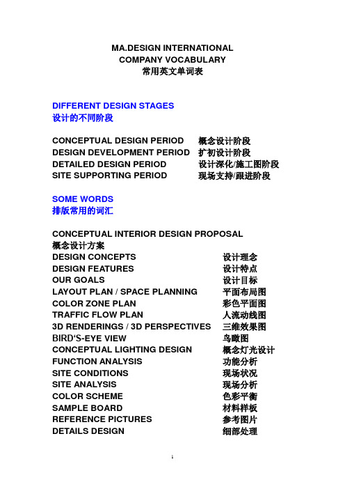
MA.DESIGN INTERNATIONALCOMPANY VOCABULARY常用英文单词表DIFFERENT DESIGN STAGES设计的不同阶段CONCEPTUAL DESIGN PERIOD 概念设计阶段DESIGN DEVELOPMENT PERIOD 扩初设计阶段DETAILED DESIGN PERIOD 设计深化/施工图阶段SITE SUPPORTING PERIOD 现场支持/跟进阶段SOME WORDS排版常用的词汇CONCEPTUAL INTERIOR DESIGN PROPOSAL概念设计方案DESIGN CONCEPTS 设计理念DESIGN FEATURES 设计特点OUR GOALS 设计目标LAYOUT PLAN / SPACE PLANNING 平面布局图COLOR ZONE PLAN 彩色平面图TRAFFIC FLOW PLAN 人流动线图3D RENDERINGS / 3D PERSPECTIVES 三维效果图BIRD‘S-EYE VIEW 鸟瞰图CONCEPTUAL LIGHTING DESIGN 概念灯光设计FUNCTION ANALYSIS 功能分析SITE CONDITIONS 现场状况SITE ANALYSIS 现场分析COLOR SCHEME 色彩平衡SAMPLE BOARD 材料样板REFERENCE PICTURES 参考图片DETAILS DESIGN 细部处理HIGHLIGHTS DESIGN 亮点设计INTERIOR DESIGN PROPOSAL 室内设计方案EXTERIOR ELEVATION RENOVATION 建筑外立面改造BIDDING PROPOSAL 投标方案PROJECT TIME SCHEDULE 项目进度表PROJECT ORGANIZATIONAL CHART 项目人员架构COMPANY INTRODUCTION 公司介绍DIFFERENT DESIGN STYLES设计的不同风格CONTEMPORARY MODERN STYLE 现代简洁风格CLASSICAL AND ELEGANT STYLE 古典贵气风格GRAND AND SIMPLE STYLE 简单大气风格CHINESE STYLE 中式风格NORTHERN EUROPEAN STYLE 北欧风格MEDITERRANEAN STYLE 地中海风格YOGA STYLE 瑜伽风格ZEN STYLE 禅风格FUSION STYLE 中西合璧风格SOME COLORS 常用色彩BLACK 黑色SILVER 银色GOLDEN 金色RED 红色WHITE 白色GREY 灰色BEIGE 米色COFFEE 咖啡色BROWN 褐色PINK 粉红色GREEN 绿色BLUE 蓝色SCARLET 绯红, 猩红PURPLE 紫色LAVENDER 淡紫色ORANGE 橙色YELLOW 黄色SMALL TIPS:DARK + 颜色= 更深的颜色LIGHT + 颜色= 更浅的颜色VOCABULARY FOR RESIDENTIAL PROJECTS居住空间类项目常用词汇(适用于样板房,酒店式公寓等)FOYER 门厅SHOE CABINET 鞋柜LIVING ROOM 客厅DINING ROOM 餐厅FAMILY ROOM 家庭起居室BEDROOM 卧室MASTER BEDROOM 主卧室GUEST BEDROOM 客卧室MASTER BATHROOM 主卫生间GUEST BATHROOM 客卫生间WALK-IN WARDROBE 走入式衣柜CHILDREN’S ROOM儿童房(SON’S ROOM / DAUGHTER’S ROOM) GRANDPARENT’S ROOM老人房STUDY 书房BAR AREA 酒吧区AV ROOM 视听室KITCHEN 厨房CORRIDOR 走道BALCONY 阳台GARDEN 花园ROOF GARDEN 屋顶花园MAID ROOM 佣人房BASEMENT 地下室GARAGE 车库VOCABULARY FOR CLUB HOUSE PROJECTS会所类项目常用词汇LIBRARY 阅览室CHILDREN’S PLAYG ROUND 儿童游乐场CIGAR + RED WINE ROOM 雪茄/ 红酒室AV ROOM 视听室POOL / SNOOKER 桌球室MAH-JONG ROOM 棋牌室GYM 健身中心SWIMMING POOL 游泳池INDOOR / OUTDOOR SWIMMING POOL室内/ 露天游泳池SPA / SAUNA 水疗/ 桑拿房RESTAURANT 餐厅CHINESE CUISINE RESTAURANT 中餐厅ITALIAN CUISINE RESTAURANT 意大利餐厅JAPANESE CUISINE RESTAURANT 日式料理WESTERN FOOD RESTAURANT 西餐厅BBQ AREA 烧烤区CAFETERIA 自助餐厅CAFÉ 咖啡吧LOUNGE 休息区BAR 酒吧JUICE BAR 果汁吧BACK KITCHEN 后厨LOBBY 大堂GARDEN 花园ROOF GARDEN 屋顶花园VOCABULARY FOR SALES OFFICE PROJECTS售楼处类项目常用词汇RECEPTION AREA 接待区/ 销控区MODEL DISPLA Y AREA 沙盘展示区UNIT MODEL DISPLA Y AREA 单体模型展示区MATERIAL DISPLA Y AREA 建材展示区DISCUSSION ROOM 洽谈室MEETING ROOM 会议室ROOM FOR SIGNING UP CONTRACTS 签约室FINANCE OFFICE 财务室CASHIER 缴费处SAMPLE ROOM AREA 样板房区域VOCABULARY FOR CORPORATE PROJECTS办公空间类项目常用词汇RECEPTION AREA 接待区LOGO WALL 公司标志墙WAITING AREA 等候区MAIL ROOM 收发室DISPLA Y AREA 展示区PRESIDENT OFFICE 总裁办公室CEO OFFICE CEO办公室GM OFFICE GM办公室DGM OFFICE DGM办公室MANAGER ROOM 经理室STAFF AREA 员工区MARKETING DEPT. 市场部SALES DEPT. 销售部ADMIN. DEPT. 行政部HR DEPT. 人事部FINANCE DEPT. 财务部AUDIT DEPT. 审计部BUSINESS DEPT. 事业部PURCHASING DEPT. 采购部MEETING ROOM 会议室CONFERENCE ROOM 大会议室VIP ROOM 贵宾室TRAINING ROOM 培训室IT ROOM 机房LIFT 电梯LIFT LOBBY 电梯间STAIRCASES 楼梯HYDRANT 消防栓PANTRY 茶水间LIBRARY 图书馆READING ROOM 阅览室STORAGE 储藏室COPY ROOM 复印室BUFFER ZONE 休息区CORRIDOR 走廊/ 走道TOILET (MALE / FEMALE) 洗手间(男/ 女)POSTER 海报ELEVATION 立面PLANTATION 绿化盆栽WATERSCAPE 水景SCULPTURE 雕塑LOW CABINET 低柜HANGING CABINET 吊柜FULL-HEIGHT CABINET 全高柜CUSTOM-MADE CABINET 定制柜PROJECTOR 投影机LOGO 公司标志LOGO WALL 标志墙/形象墙SOME MATERIAL常用建材WALL FINISHING 墙面处理WALLPAPER 墙纸WALLCOVERING 墙布ART PAINTING 挂画EMULSION PAINTING 乳胶漆POSTER 海报WOODEN CARVING 木雕MIRROR 镜子ART MIRROR 艺术镜子DOOR, WINDOW AND PARTITION 门窗及隔断DOOR FRAME 门框WINDOW FRAME 窗框DOUBLE-LEAF DOOR 双扇门SINGLE-LEAF DOOR 单扇门ONE-AND-A-HALF-LEAF DOOR 子母门HIDDEN DOOR 暗门SCREEN 屏风PARTITION 隔断FOLDABLE PARTITON 折叠式隔断屏风CEILING FINISHING 天花处理CEILING 天花FALSE CEILING 假天花FALSE CEILING TILE 天花矿棉板CEILING CORNICE 顶角线SKIRTING 踢脚线FLOOR FINISHING 地面处理CERAMIC TILE 瓷砖PVC TILE 胶地板CIMIC 玻化砖CARPET 地毯RUG 装饰块毯SPOT LIGHT 射灯DOWN LIGHT 筒灯FLOOR LAMP 立灯WALL LAMP 壁灯TABLE LAMP 台灯HANGING LAMP 吊灯FLUORESCENT 日光灯HVAC SYSTEM 空调系统FIRE SERVICE SYSTEM 消防系统INTELLIGENT SYSTEM 智能系统LIGHTING CONTROL SYSTEM 灯光控制系统DATA/VOICE SYSTEM 弱电(数据/语音)系统SECURITY SYSTEM 门禁系统QUEUE SYSTEM 叫号系统BACKGROUND MUSIC SYSTEM 背景音乐系统BROADCASTING SYSTEM 广播系统CCTV SYSTEM 监控系统M&E WORKS 机电工程P&D WORKS 给排水工程STONE & GLASS 石材及玻璃MANMADE STONE 人造石SLATE 板岩MARBLE 大理石FROSTED GLASS 磨砂玻璃TEMPER GLASS 清玻璃TOUGHENED GLASS 强化玻璃ART GLASS 艺术玻璃BACK PAINTED GLASS 烤漆玻璃STAINLESS STEEL 不锈钢PEBBLE 鹅卵石FABRIC 布艺LEATHER 皮革CURTAIN 窗帘VERTICAL BLINDS 垂直帘ROLLER BLINDS 卷帘BEAD CURTAIN 珠帘SAND 沙CEMENT 水泥PLASTER 石膏GYPSUM BOARD 石膏板CONCRETE 混凝土REINFORCED CONCRETE 钢筋混凝土GRAVEL 碎石BRICK 砖BEAM 梁COLUMN 柱ARCH 拱SCAFFOLD 脚手架PIPE,CONDUIT 管WIRING 线FURNITURE AND DECOR家具及装饰品TOILET 马桶SINK 台盆SINK FAUCET 台盆龙头SHOWER FAUCET 淋浴龙头SHOWER ROOM 淋浴间BATHTUB 浴缸SOAP HOLDER 皂架PAPER HOLDER 卷纸架HAND DRIER 干手机TRASH CAN 垃圾桶EXHAUSTING FAN 排风扇TOWEL ROD 毛巾杆DECOR 装饰品SCULPTURE 雕塑PLANTATION 绿化盆栽ARTIFICAL FLOWER 仿真花艺CANDLE HOLDER 烛台ANTIQUES 古董CUSHION 靠垫BEDDING 床上用品COSMETICS 化妆品STATIONERY 文具TABLEWARE 餐具DINGING ROOM 餐厅DINING TABLE 餐桌DINING CHAIR 餐椅DINING CABINET 餐边柜SIDE TABLE 案几FLOWER STAND 花架FOLDABLE PARTITON/SCREEN 屏风BAR TABLE 吧台BAR CHAIR 吧椅LIVING ROOM 客厅SINGLE SOFA 单人沙发TWO SEATED SOFA 双人沙发THREE SEATED SOFA 三人沙发ORIGINAL ART CHAIR 原创艺术椅子COFFEE TABLE 茶几CORNER TABLE 角几TV CABINET 电视柜SIDE TABLE 案几BEDROOM 卧室SINGLE BED 单人床DOUBLE BED 双人床BED-SIDE TABLE 床边柜BED STOOL 床尾凳TV CABINET 电视柜MAKE-UP DESK 梳妆台MAKE-UP CHAIR 梳妆椅WARDROBE 衣柜CLOTHES RACK 衣架LAZE CHAIR 休闲椅SOFA 休闲沙发STUDY 书房DESK 书桌CHAIR 书桌椅/电脑椅COMPUTER DESK 电脑桌BOOK SHELF 书架CD SHELF 唱片架KITCHEN 厨房PLATE RACK 碗盘架HOOK 粘钩ARTIFICAL FOOD 仿真食品ARTIFICAL FRUIT 仿真水果DISHRAG 抹布TRASH BIN 垃圾桶BATHROOM 主卫生间TOILETARY 卫浴用品TOWEL 毛巾BATH ROBE 浴袍SLIPPERS 拖鞋MATH 地垫SOAP HOLDER 肥皂缸TISSUE BOX 纸巾盒DECOR PAINTING 装饰画BALCONY 阳台OUTDOOR COFFEE TABLE 室外茶几OUTDOOR LAZE CHAIR 室外椅OUTDOOR SWING CHAIR 室外千秋GRILL 室外烧烤架。
Conceptual Design
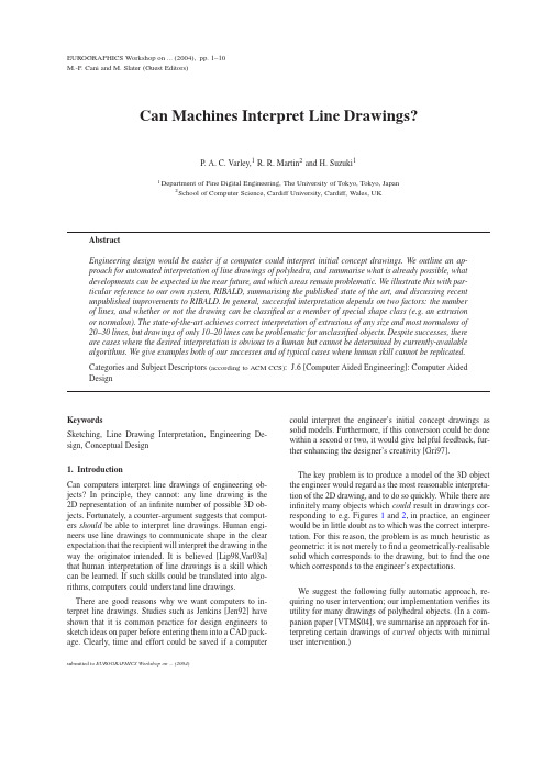
EUROGRAPHICS Workshop on...(2004),pp.1–10M.-P.Cani and M.Slater(Guest Editors)Can Machines Interpret Line Drawings?P.A.C.Varley,1R.R.Martin2and H.Suzuki11Department of Fine Digital Engineering,The University of Tokyo,Tokyo,Japan2School of Computer Science,Cardiff University,Cardiff,Wales,UKKeywordsSketching,Line Drawing Interpretation,Engineering De-sign,Conceptual Design1.IntroductionCan computers interpret line drawings of engineering ob-jects?In principle,they cannot:any line drawing is the 2D representation of an infinite number of possible3D ob-jects.Fortunately,a counter-argument suggests that comput-ers should be able to interpret line drawings.Human engi-neers use line drawings to communicate shape in the clear expectation that the recipient will interpret the drawing in the way the originator intended.It is believed[Lip98,Var03a] that human interpretation of line drawings is a skill which can be learned.If such skills could be translated into algo-rithms,computers could understand line drawings.There are good reasons why we want computers to in-terpret line drawings.Studies such as Jenkins[Jen92]have shown that it is common practice for design engineers to sketch ideas on paper before entering them into a CAD pack-age.Clearly,time and effort could be saved if a computer could interpret the engineer’s initial concept drawings as solid models.Furthermore,if this conversion could be done within a second or two,it would give helpful feedback,fur-ther enhancing the designer’s creativity[Gri97].The key problem is to produce a model of the3D object the engineer would regard as the most reasonable interpreta-tion of the2D drawing,and to do so quickly.While there are infinitely many objects which could result in drawings cor-responding to e.g.Figures1and2,in practice,an engineer would be in little doubt as to which was the correct interpre-tation.For this reason,the problem is as much heuristic as geometric:it is not merely tofind a geometrically-realisable solid which corresponds to the drawing,but tofind the one which corresponds to the engineer’s expectations.We suggest the following fully automatic approach,re-quiring no user intervention;our implementation verifies its utility for many drawings of polyhedral objects.(In a com-panion paper[VTMS04],we summarise an approach for in-terpreting certain drawings of curved objects with minimal user intervention.)submitted to EUROGRAPHICS Workshop on (2004)2P .Varley &R.Martin &H.Suzuki /Can Machines Interpret LineDrawings?Figure 1:Trihedral Draw-ing[Yan85]Figure 2:Non-Trihedral Drawing [Yan85]•Convert the engineer’s original freehand sketch to a line drawing.This is described in Section 3.•Determine the frontal geometry of the object.The three most crucial aspects of this are:–Label the lines in the drawing as convex,concave,or occluding.See Section 4.–Determine which pairs of lines in the drawing are in-tended to be parallel in 3D.See Section 5.–Inflate the drawing to 212D”).In a frontal geometry,everything visible in the nat-ural line drawing is given a position in 3D space,but the oc-cluded part of the object,not visible from the chosen view-point,is not present.A polyhedron is trihedral if three faces meet at each ver-tex.It is extended trihedral [PLVT98]if three planes meet at each vertex (there may be four or more faces if some are coplanar).It is tetrahedral if no more than four faces meet at any vertex.It is a normalon if all edges and face normals are aligned with one of three main perpendicular axes.Junctions of different shapes are identified by letter:junc-tions where two lines meet are L-junctions ,junctions of three lines may be T-junctions ,W-junctions or Y-junctions ,and junctions of four lines may be K-junctions ,M-junctions or X-junctions .Vertex shapes follow a similar convention:for example,when all four edges of a K-vertex are visible,the drawing has four lines meeting at a K -junction.When reconstructing an object from a drawing,we take the correct object to be the one which a human would decide to be the most plausible interpretation of the drawing.3.Convert Sketch to Line DrawingFor drawings of polyhedral objects,we believe it to be most convenient for the designer to input straight lines directly,and our own prototype system,RIBALD,includes such an interface.However,it could be argued that freehand sketch-ing is more “intuitive”,corresponding to a familiar interface:pen and paper.Several systems exist which are capable of converting freehand sketches into natural line drawings—see e.g.[ZHH96],[Mit99],[SS01].4.Which Lines are Convex/Concave?Line labelling is the process of determining whether each line in the drawing represents a convex,a concave,or an oc-cluding edge.For drawings of trihedral objects with no hole loops,the line labelling problem was essentially solved by Huffman [Huf71]and Clowes [Clo70],who elaborated the catalogue of valid trihedral junction labels.This turns line labelling into a discrete constraint satisfaction problem with 1-node constraints that each junction must have a label in the catalogue and 2-node constraints that each line must have the same label throughout its length .The Clowes-Huffman catalogue for L -,W -and Y -junctions is shown in Figure 3;+indicates a convex edge,−indicates a concave edge,and an arrow indicates an occluding edge with the occluding face on the right-hand side of the arrow.In trihedral objects,T -junctions (see Figure 4)are always occluding.For trihedral objects,algorithms for Clowes-Huffman line labelling,e.g.those of Waltz [Wal72]and Kanatani [Kan90],although theoretically taking O (2n )time,are usually O (n )insubmitted to EUROGRAPHICS Workshop on (2004)P .Varley &R.Martin &H.Suzuki /Can Machines Interpret Line Drawings?3+-+-+-+++---Figure 3:Clowes-HuffmanCatalogueFigure 4:Occluding T -Junctionspractice [PT94].It is believed that the time taken is more a function of the number of legal labellings than of the algo-rithm,and for trihedral objects there is often only a single legal labelling.For example,Figure 1has only one valid la-belling if the trihedral (Clowes-Huffman)catalogue is used.Extending line labelling algorithms to non-trihedral nor-malons is fairly straightforward [PLVT98].The additional legal junction labels are those shown in Figure 5.Note,how-ever,that a new problem has been introduced:the new T -junctions are not occluding.-+-+-+Figure 5:Extended Trihedral JunctionsExtension to the 4-hedral general case is less straight-forward.The catalogue of 4-hedral junction labels is much larger [VM03]—for example,Figure 6shows just the possi-bilities for W -junctions.Because the 4-hedral catalogue isno+-+-+-Figure 6:4-Hedral W -Junctionslonger sparse ,there are often many valid labellings for each drawing.Non-trihedral line labelling using the previously mentioned algorithms is now O (2n )in practice as well as in theory,and thus too slow.Furthermore,choosing the best labelling from the valid ones is not straightforward either,although there are heuristics which can help (see [VM03]).Instead,an alternative labelling method is to use a relax-ation bel probabilities are maintained for each line and each junction;these probabilities are iteratively up-dated.If a probability falls to 0,that label is removed;if a probability reaches 1,that label is chosen and all other la-bels are removed.In practice,this method is much faster—labels which are possible but very unlikely are removed quickly by relaxation,whereas they are not removed at all by combinatorial algorithms.However,relaxation methods are less reliable (the heuristics developed for choosing between valid labellings when using combinatorial methods are rea-sonably effective).In test we performed on 535line draw-ings [Var03b],combinatorial labelling labelled 428entirely correctly,whereas relaxation labelling only labelled 388en-tirely correctly.The most serious problem with either approach is that in treating line labelling as a discrete constraint satisfaction problem,the geometry of the drawing is not taken into ac-count,e.g.the two drawings in Figure 7are labelled the same.The problems created by ignoring geometrybecomeFigure 7:Same Topologymuch worse in drawings with several non-trihedral junctions (see [VSM04]),and for these,other methods are required.A new approach to labelling outlined in that paper and subsequently developed further [VMS04]makes use of an idea previously proposed for inflation [LB90]:•Assign relative i ,j ,k coordinates to each junction by as-suming that distances along the 2D axes in Figure 8cor-respond to 3D distances along spatial i ,j ,k axes.•Rotate the object from i ,j ,k to x ,y ,z space,where the lat-ter correspond to the 2D x ,y axes and z is perpendicular to the plane of the drawing.•Find the 3D equation for each planar region using vertex x ,y ,z coordinates.•For each line,determine from the equations of the two faces which meet the line whether it is convex,concave or occluding (if there is only one face,the line is occluding).submitted to EUROGRAPHICS Workshop on (2004)4P .Varley &R.Martin &H.Suzuki /Can Machines Interpret LineDrawings?+k-k+i-i+j-jFigure 8:Three Perpendicular Axes in 2DOn its own,this method does not work well:e.g.it is dif-ficult to specify a threshold distance d between two faces such that a distance greater than d corresponds to a step,and hence an occluding line,while if the distance is less than d the planes meet and the line is convex or concave.However,using the predictions made by this method as input to a re-laxation labelling algorithm provides far better results than using arbitrary initialisation in the same algorithm.This idea can be combined with many of the ideas in Sec-tion 6when producing a provisional geometry.Various vari-ants of the idea have been considered (see [VMS04]),partic-ularly with reference to how the i ,j ,k axes are identified in a 2D drawing,without as yet any firm conclusions as to which is best overall.Another strength is that the idea uses the relaxation labeller to reject invalid labellings while collat-ing predictions made by other approaches.This architecture allows additional approaches to labelling,such as Clowes-Huffman labelling for trihedral objects,to make a contribu-tion in those cases where they are useful [VMS04].Even so,the current state-of-the-art only labels approxi-mately 90%of non-boundary edges correctly in a represen-tative sample of drawings of engineering objects [VMS04].Note that any approach which uses catalogue-based la-belling can only label those drawings whose vertices are in a catalogue—it seems unlikely that 7-hedral and 8-hedral ex-tended K-type vertices of the type found in Figure 9willbeFigure 9:Uncatalogued Verticescatalogued in the near future.In view of this,one must ques-tion whether line labelling is needed.Humans are skilled at interpreting line drawings,and introspection tells us that line labelling is not always a part of this process—it may evenbe that humans interpret the drawing first,and then (if nec-essary)determine which lines are convex,concave and oc-cluding from the resulting mental model.Our investigations indicate that line labelling is needed,at least at present.We are investigating interpreting line draw-ings without labelling,based on identifying aspects of draw-ings which humans are known or believed to see quickly,such as line parallelism [LS96],cubic corners [Per68]and major axis alignment [LB90].Current results are disappoint-ing.Better frontal geometry can be obtained if junction la-bels are available.More importantly,the frontal geometry is topologically unsatisfactory.Distinguishing occluding from non-occluding T -junctions without labelling information is unreliable,and as a result,determination of hidden topology (Section 8)is unlikely to be successful.5.Which Lines are Parallel?Determining which lines in a drawing are intended to be par-allel in 3D is surprisingly difficult.It is,for example,obvious to a human which lines in the two drawings in Figure 10are intended to be parallel and which are not,but determining this algorithmically presentsproblems.Figure 10:Which Lines are Parallel?Sugihara [Sug86]attempted to define this problem away by using a strict definition of the general position rule:the user must choose a viewpoint such that if lines are parallel in 2D,the corresponding edges in 3D must be parallel.This makes no allowance for the small drawing errors which in-evitably arise in a practical system.Grimstead’s “bucketing”approach [Gri97],grouping lines with similar orientations,works well for many draw-ings,but fails for both drawings in Figure 10.Our own “bundling”approach [Var03a],although somewhat more re-liable,fares no better with these two drawings.The basic idea used in bundling is that edges are parallel if they look parallel unless it can be deduced from other information that they cannot be parallel.The latter is problematic for two rea-sons.Firstly,if ‘other information’means labelling,iden-tification of parallel lines must occur after labelling,limit-ing the system organisation for computing frontal geome-try.Secondly,to cover increasingly rare exceptional cases,we must add extra,ever more complex,rules for deducing which lines may or may not be parallel.This is tedious andsubmitted to EUROGRAPHICS Workshop on (2004)P.Varley&R.Martin&H.Suzuki/Can Machines Interpret Line Drawings?5 rapidly reaches the point of diminishing returns.For exam-ple,a rule which can deduce that the accidental coincidencein Figure11should not result in parallel lines would be bothcomplicated to implement and of no use in many other cases.**Figure11:Accidental CoincidenceFurthermore,there are also cases where it is far from cleareven to humans which edges should be parallel in3D(edgesA,B,C and D in Figure12are a case in point).ABCDFigure12:Which Edges Should Be Parallel?In view of these problems,more recent approaches tofrontal geometry(e.g.[VMS04])simply ignore the possi-bility that some lines which appear parallel in2D cannot infact be parallel in3D.Initially,it is assumed that they areparallel;this information is then re-checked after inflation.6.Inflation to212D by assigning z-coordinates(depth coordinates)to eachvertex,producing a frontal geometry.The approach taken here is the simplest:we use compliance functions[LS96]to generate equations linear in vertex depth coordinates,and solve the resulting linear least squares problem.Many com-pliance functions can be translated into linear equations in z-coordinates.Of these,the most useful are:Cubic Corners[Per68],sometimes called corner orthogo-nality,assumes that a W-junction or Y-junction corresponds to a vertex at which three orthogonal faces meet.See Fig-ure13:the linear equation relates depth coordinates z V and z A to angles F and G.Nakajima[Nak99]reports successful creation of frontal geometry solely by using a compliance function similar to corner orthogonality,albeit with a limited set of test drawings in which orthogonality predominates. Line Parallelism uses two edges assumed to be parallel in 3D.The linear equation relates the four z-coordinates of theVA BCEFGVABCEFGFigure13:Cubic Cornersvertices at either end of the two edges.Line parallelism is not,by itself,inflationary:there is a trivial solution(z=0 for all vertices).Vertex Coplanarity uses four vertices assumed to be coplanar.The linear equation relating their z-coordinates is easily obtained from2D geometry.Vertex coplanarity is also not,by itself,inflationary,having the trivial solution z=0 for all vertices.General use of four-vertex coplanarity is not recommended(Lipson[Lip98]notes that if three vertices on a face are collinear,four-vertex coplanarity does not guar-antee a planar face).However,it is invaluable for cases like those in Figure14,to link vertices on inner and outer face loops:without it the linear system of depth equations would be disjoint,with infinitely many solutions.**Figure14:Coplanar VerticesLipson and Shpitalni[LS96]list the above and several other compliance functions;we have devised the following. Junction-Label Pairs[Var03a]assumes that pairs of junc-tions with identified labels have the same depth implications they would have in the simplest possible drawing contain-ing such a pair.An equation is generated relating the vertex depths at each end of the line based on the junction labels of those vertices.For example,see Figure15:this pair of junc-tion labels can be found in an isometric drawing of a cube, and the implication is that the Y-junction is nearer to the viewer than the W-junction,with the ratio of2D line length to depth change being√6P .Varley &R.Martin &H.Suzuki /Can Machines Interpret LineDrawings?Figure 15:Junction La-bel Pair *Figure 16:Incorrect Infla-tion?paper.Although it occasionally fails to determine correctly which end of a line should be nearer the viewer,such failures arise in cases like the one in Figure 16where a human would also have difficulty.The only systematic case where using a linear system of compliance functions fails is for Platonic and Archimedean solids,but a known special-case method (Marill’s MSDA [Mar91])is successful for these.In order to make the frontal geometry process more ro-bust when the input information (especially line labelling)is incorrect,we have experimented with two approaches to inflation which do without some or all of this information.The first is the ‘preliminary inflation’described in Sec-tion 4:find the i ,j ,k axes in the drawing,inflate the object in i ,j ,k space,then determine the transformation between i ,j ,k and x ,y ,z spaces.This requires parallel line information (to group lines along the i ,j ,k axes).Where such information is misleading,the quality of inflation is unreliable,but this is not always a problem,e.g.the left-hand drawing in Figure 10is labelled correctly despite incorrect parallel line informa-tion.Once (i)a drawing has been labelled correctly and (ii)there is reason to suppose that the parallel line information is unreliable,better-established inflation methods can be used to refine the frontal geometry.However,the right-hand draw-ing is one of those which is not labelled correctly,precisely because of the misleading parallel line information.A second promising approach,needing further work,at-tempts to emulate what is known or hypothesised about hu-man perception of line drawings.It allocates merit figures to possible facts about the drawing;these,and the geometry which they imply,are iteratively refined using relaxation:•Face-vertex coplanarity corresponds to the supposition that vertices lie in the plane of faces.We have already noted the difficulty of distinguishing occluding from non-occluding T -junctions;to do so,we must at some time decide which vertices do lie in the plane of a face.•Corner orthogonality ,which was described earlier.At least one inflationary compliance function is required,and this one has been found reliable.Although limited in prin-ciple,corner orthogonality is particularly useful in prac-tice as cubic corners are common in engineering objects.•Major axis alignment is the idea described above of using i ,j ,k axes.This is also an inflationary compliance func-tion.It is newer than corner orthogonality,and for this reason considered less reliable.However,unlike cornerorthogonality (which can fail entirely in some circum-stances),major axis alignment does always inflate a draw-ing,if not always entirely correctly.•Line parallelism is useful for producing ‘tidy’output (e.g.to make lines terminating in occluding T -junctions paral-lel in 3D to other lines with similar 2D orientation).How-ever,the main reason for its inclusion here is that it also produces belief values for pairs of lines being parallel as a secondary output,solving the problem in Section 5.•Through lines correspond to the requirement that a contin-uous line intercepted by a T -junction or K -junction corre-sponds to a single continuous edge of the object.A third,simpler,approach assumes that numerically cor-rect geometry is not required at this early stage of pro-cessing,and identifying relative depths of neighbouring ver-tices is sufficient.Schweikardt and Gross’s [SG00]work,al-though limited to objects which can be labelled using the Clowes-Huffman catalogue,and not extending well to non-normalons,suggests another possible way forward.7.Classification and SymmetryIdeally,one method should work for all drawings of poly-hedral objects;identification of special cases should not be necessary.However,the state-of-the-art is well short of this ideal—in practice it is useful to identify certain frequent properties of drawings and objects.Identification of planes of mirror symmetry is particularly useful.Knowledge of such a symmetry can help both to construct hidden topol-ogy (Section 8)and to beautify the resulting geometry (Sec-tion 9).Identification of centres of rotational symmetry is less useful [Var03a],but similar methods could be applied.The technique adopted is straightforward:for each possi-ble bisector of each face,create a candidate plane of mirror symmetry,attempt to propagate the mirror symmetry across the entire visible part of the object,and assess the results us-ing the criteria of (i)to what extent the propagation attempt succeeded,(ii)whether there is anything not visible which should be visible if the plane of mirror symmetry were a genuine property of the object,and (iii)how well the frontal geometry corresponds to the predicted mirror symmetry.Classification of commonly-occurring types of objects (examples include extrusions,normalons,and trihedral ob-jects)is also useful [Var03a],as will be seen in Section 8.One useful combination of symmetry and classification is quite common in engineering practice (e.g.see Figures 1and 2):a semi-normalon (where many,but not all,edges and face normals are aligned with the major axes)also having a dominant plane of mirror symmetry aligned with one of the object’s major axes [Var03a].The notable advantage of this classification is that during beautification (Section 9)it pro-vides constraints on the non-axis-aligned edges and faces.We recommend that symmetry detection and classifica-submitted to EUROGRAPHICS Workshop on (2004)P.Varley&R.Martin&H.Suzuki/Can Machines Interpret Line Drawings?7tion should be performed after creation of the frontal geom-etry.Detecting candidate symmetries without line labels is unreliable,and assessing candidate symmetries clearly ben-efits from the3D information provided by inflation.The issue is less clear for classification.Some classifications (e.g.whether the object is a normalon)can be done directly from the drawing,without creating the frontal geometryfirst. However,others cannot,so for simplicity it is preferable to classify the object after creating its frontal geometry.8.Determine Hidden TopologyOnce the frontal geometry has been determined,the next stage of processing is to add the hidden topology.The method is essentially that presented in[VSMM00]:firstly, add extra edges to complete the wireframe,and then add faces to the wireframe to compete the object,as follows:While the wireframe is incomplete:•Project hypothesised edges from each incomplete vertex along the appropriate axes•Eliminate any edges which would be visible at their points of origin•Find locations where the remaining edges intersect,as-signing meritfigures according to how certain it is that edges intersect at this location(e.g.an edge intersecting only one other edge has a higher meritfigure than an edge has potential intersections with two or more other edges)•Reduce the merit for any locations which would be visible (these must be considered,as drawing errors are possible)•Choose the location at which the merit is greatest •Add a vertex at this location,and the hypothesised edges meeting at this location,to the known object topology The process of completing the wireframe topology varies in difficulty according to the type of object drawn.We il-lustrate two special-case object classes,extrusions and nor-malons,and the general case.In some cases(e.g.if the ob-ject is symmetrical or includes a recognised feature),more than one vertex can be added in one iteration,as described in[Var03a].Such cases increase both the speed and reliabil-ity of the process of completing the wireframe. Completing the topology of extrusions from a known front end cap is straightforward.Figure17shows a draw-ing and the corresponding completed extrusionwireframe.Figure17:ExtrusionKnowing that the object is a normalon simplifies recon-struction of the wireframe,since when hypothesised edges are projected along axes,there is usually only one possibil-ity from any particular incomplete vertex.Figure18shows a drawing of a normalon and the corresponding completed wireframe.Similarly,if the object is trihedral,there canbeFigure18:Normalon[Yan85]at most one new edge from each incomplete vertex,simplify-ing reconstruction of the correct wireframe.Figure19shows a drawing of a trihedral object and the corresponding com-pletedwireframe.Figure19:Trihedral Object[Yan85] However,in the general case,where the object is neither a normalon nor trihedral,there is the significant difference that hypothesised edges may be projected in any direction paral-lel to an existing edge.Even after eliminating edges which would be visible,there may be several possibilities at any given incomplete vertex.The large number of possible op-tions rapidly becomes confusing and it is easy to choose an incorrect crossing-point at an early stage.Although such er-rors can sometimes be rectified by backtracking,the more common result is a valid but unwanted wireframe.Only very simple drawings can be processed reliably.Figure20shows a general-case object and the corresponding completed wire-frame;this represents the limit of the current state of theart.Figure20:General Case ObjectOne particular problem,a specific consequence of the ap-proach of completing the wireframe before faces,is thatsubmitted to EUROGRAPHICS Workshop on (2004)8P.Varley&R.Martin&H.Suzuki/Can Machines Interpret Line Drawings?there is no assurance that the local environments of either end of a new edge match.It may happen that a sector around a new edge is solid at one end and empty at the other.This is perhaps the single most frequent cause of failure at present, and is especially problematic in that the resulting completed wireframe can appear correct.We aim to investigate faster and more reliable ways of determining the correct hidden topology of an object,starting with approaches aimed at cor-recting this conflicting local environment problem. Adding additional faces to the completed wireframe topology for which the frontal geometry is already known is straightforward.We use repeated applications of Dijkstra’s Algorithm[Dij59]tofind the best loop of unallocated half-edges for each added face,where the merit for a loop of half-edges is based both on the number of half-edges re-quired(the fewer,the better)and their geometry(the closer to coplanar,the better).We have not known this approach to fail when the input is a valid wireframe(which,as noted above,is not always the case).9.Beautification of Solid ModelsAs can be seen from the Figures in the previous Section, even when topologically correct,the solid models produced may have(possibly large)geometric imperfections.They re-quire‘beautification’.More formally,given a topologically-correct object and certain symmetry and regularity hypothe-ses,we wish to translate these hypotheses into constraints, and update the object geometry so that it maximises some merit function based on the quantity and quality of con-straints enforced.In order to make this problem more tractable,we decom-pose it into determination of face normals and determination of face distances from the origin;once faces are known,ver-tex coordinates may be determined by intersection.The ra-tionale for this partitioning[KY01]is that changing face nor-mals can destroy satisfied distance constraints,but changing face distances cannot destroy satisfied normal constraints. However,there are theoretical doubts about this sub-division,related to the resolvable representation prob-lem[Sug99]offinding a‘resolution sequence’in which information can befixed while guaranteeing that no previ-ous information is contradicted.For example,determining face equationsfirst,and calculating vertex coordinates from them,is a satisfactory resolution sequence for many polyhe-dra,including all trihedral polyhedra.Similarly,fixing vertex coordinates and calculating face planes from them is a satis-factory resolution sequence for deltahedra and triangulated mesh models.Sugihara[Sug99]proved that:•all genus0solids have resolution sequences(although if neither trihedral nor deltahedra,finding the resolution se-quence might not be straightforward);•(by counterexample)genus non-zero solids do not neces-sarily have resolution sequences.Thus,there are two resolvable representation issues:•finding a resolution sequence for those solids which have a non-trivial resolution sequence;•producing a consistent geometry for those solids which do not have a resolution sequence.Currently,neither problem has been solved satisfactorily. Thus,although there are objects which have resolution se-quences,but for which determining face normals,and then face distances,andfinally vertex coordinates,is not a satis-factory resolution sequence,the frequency of occurrence of such objects has yet to be determined.If low,the pragmatic advantages of such an approach are perhaps more important than its theoretical inadequacy.Our overall beautification algorithm is[Var03a]:•Make initial estimates of face normals•Use any object classification to restrict face normals •Identify constraints on face normals•Adjust face normals to match constraints •Make initial estimates of face distances •Identify constraints on face distances•Adjust face distances to match constraints •Obtain vertex locations by intersecting planes in threes •Detect vertex/face failures and adjust faces to correct them We use numerical methods for constraint processing,as this seems to be the approach which holds most promise.Al-ternatives,although unfashionable for various reasons,may become more viable as the state of the art develops:see Lip-son et al[LKS03]for a discussion.In addition to the resolvable representation problem,there is a further theoretical doubt about this approach.When at-tempting to satisfy additional constraints,it is necessary to know how many degrees of freedom are left in the system once previous,already-accepted,constraints are enforced. This apparently-simple problem appears to have no fully-reliable solution.One solution proposed by Li[LHS01]per-turbs the variables slightly and detects which constraints have been violated.However,this is slow,and not necessar-ily theoretically sound either(e.g.a constraint relating face distances A and B may allow them to move together,but not independently of one another).Two differing approaches have been tried to the problem offinding whether or not a geometry exists which satis-fies a new constraint while continuing to satisfy previously-accepted constraints.Thefirst encodes constraint satisfaction as an error func-tion(the lower the value,the better-satisfied the con-straint),and face normals and/or face distances as vari-ables,using a downhill optimiser to minimise the error function[CCG99,LMM02,Var03a].Such algorithms use a ‘greedy’approach,in which the constraint with the highest figure of merit is always accepted and enforced,and then for each other constraint,in descending order of merit:if thesubmitted to EUROGRAPHICS Workshop on (2004)。
工业设计相关英语

工业设计相关英语CONCEPTUAL DESIGN1.设计等同于交流design = communication2.策划/市场management / marketing3.设计/制造engineering / manufacture4.人类工程学ergonomics5.策略–分析strategy----analysis6.创新–概念concept----innovation7.说明–定义specification----define8.最优化optimize9.有效utility10.外观appearance11.容易维护easy of maintenance12.低成本low costs13.交流communication14.计划chedule15.时间分配time allocation16.分析的关键途径critical path analysis17.工程号码job number18.工作指导卡job sheets19.花费expenses20.大纲核对checking against the brief21.重新确定方向reestablish direction22.控制质量controlling quality23.逻辑推断moving design along24.处理异议handling disagreements25.不合理的结构ill-structured problem26.合理的结构well-structured27.头脑风暴brainstrom28.概念设计conceptual design29.具象性设计embodiment design30.细节设计detail design31.外部信息outer activity32.顾客需求customer requirement33.市场调研market research34.设计说明design specifecation35.设想草绘idea sketch36.粗略手绘rough sketch37.设计图纸working drawing38.打样mockup39.信息分类classicfication of information40.市场环境market environment41.竞争对手产品competitive products42.产品历史product history43.被取代的品牌brand predecessors44.市场价格规律ruling market prices45.定量经济学economics quantities46.使用者身份identity of user47.使用的环境nvironment at point of use48.使用动机user motivation49.使用者生活模式user lifestyle50.人机界面interface51.剧情设计user scenarios52.机械学mechanics53.构造construction54.受限尺寸limited dimension55.产品用料product matiral56.资源facilities57.加工制造manufacture58.抛光finish59.烤漆paint60.美学aesthetics61.从现有数据收集gathered from existing data62.从原始数据推论derived from original data63.特殊目录specialty catalogues64.统计摘要statistical abstracts65.联想趋势trade association66.预想调查anticipatory research67.实际调查consequential research68.专利搜索patent search69.定义问题definition of problems70.准备工作preparation71.计划planning72.选择顾客群selection of user group73.评估面谈需求estimate of number of interviews requires74.准备问卷调查preparation of questionnaire75.失败的案例调查field investigation76.图表/分析/解释tabulation / analysis / interpretation77.写报告writing the report78.设计方针design guideline79.车间流程workshop processes80.快照snap shot81.接受关键部分scenarios of key issues82.消极的场景negative scenes83.积极的场景positive scenes EMBODIMENT DESIGN84.框架framework85.理解感知水帄level of perception86.精确的功能问题mathematical or fuctional problem87.艺术作品work of art88.人的进化evolution of man89.保护色protection color90.攻击性(明亮色,大码) aggression (bright color,large size)91.不同种类的风格stylistic variations92.小型化miniaturization93.电子产品electronics94.交互作用interaction95.对比contrast96.表面抛光夺目surface finished97.精确precise98.点阵排列foot print99.稳定性stability100. 可调节adjustable101.标准化standardization 102.全球化globalization103.象征性表达symbolism expression 104.苗条化slim105.可穿戴wearable106.速度感speedy107.个性化饰品styled ornamentation 108.孔洞vent109.图案pattern110.视觉帄衡visual equilibrium 111.对称帄衡symmetrical balance 112.左右对称bilateral symmetry 113.放射对称radial symmetry 114.不对称帄衡asymmetrical balance 115.比例关系proportion116.黄金分割法Golden proportion 117. 斐波纳契数列Fibonacci series 118.调和级数harmonic progression 119.节奏感rhythm120.重复repetition121.间隔alternation122.渐变gradation123.强调emphasis124.焦点point of focus 125.中断interruption126.协调harmony127.统一oneness128.一系列uniformity 129.接近proximity130.分离isolate131.引起共鸣sympathize 132.改变大小change size 133.替代品substitute134.生气勃勃animate135.有机organic136.扭曲distort137.补充supplement 138.矛盾contradict139.颠倒reverse140.故事性mythologize 141.组合combine142.象征性symbolize 143.转化transform144.趣味模仿parody145.视觉玩笑visual joke 146.相减subtract147.类推analogize148.基本要素essential elements 149.强烈intensity150.光谱color spectrum 151.色相hue152.明度lightness153.彩度saturation154.蒙赛尔色系munsell systerm155.色域color gamut156.感性构造perceived structure 157.东方性orientation158.可见性visibility159.耐用的外观durability of appearance 160.易维护maintenance161.理论上theoretic162.单色彩monochromatic163.相邻色apposite color164.互补色complementary165.三合一色triadic166.弱对比split complementary 167.半透明translucence168.金属处理metallic treatment 169.伪装色chameleon colors 170.霜状frost171.压条法layering172.光泽gloss173.全抛光sheer-high gloss174.喷漆spray-paint175.咬花texture176.压克力acry177.压克力(蓝光) acry(blue light) 178.灯led179.电镀electroplate180.镀锌galvanization181.拉丝surface brush182.铝拉丝brushed aluminum 183.金属网metal net184.银色silver185.铝aluminum186.橡胶rubberB挡板USB cover 188.铁件chassisB&音频插孔USB&AUDIO port DETAIL DESIGN190.模具die191.滑块sliding block 192.公母模feature die193.水洗rinse194.阳性处理anodize195.拆模dismantle the die 196.喷沙sand blasting 197.打浇口degate198.段面咬花satin texture 199.镁铝合金magnalium 200.通孔形式through-hole form 201.简易模plain die202.冲孔模pierce die203.成型模forming die 204.工程图procedure dwg205.定位块located block206.压缩成型compre sion molding 207.脱料板striper plate208.热浇道hot runner209.挤出成型extrusion molding 210.高压铸造squeeze casting 211.精密铸造investment casting 212.通气阀air vent vale213.托架bracket214.定位销dowel pin215.顶出杆ejector rod216.引导柱guide post217.导轨guide rail218.浇口gate219.分模线paring line220.滚桶roller221.主轴spindle222.方螺纹square thread223.止动梢stop pin224.三条螺纹three start screw 225.通气孔vent226.搪孔机boring machine C 铣床CNC milling machine 228.轮廓锯床contouring machine 229.仿形磨床copy grinding machine 230.仿形车床copy lathe231.加工制造中心machine center232.线割放电加工机wire E.D.M233.合金工具钢alloy tool steel234.不锈钢stainless steel235.塑胶覆面钢材vinyltapped steel sheet 236.老化处理ageing237.气体硬化air hardening238.退火annealing239.阳极氧化处理anodizing240.奥氏体等温淬火austempering241.滚镀barrel plating242.辉面电镀bright electroplating 243.渗碳carburizing244.脱碳退火decarburization 245.扩散diffusion246.压花embossing247.表面蚀刻etching248.硬化性hardenability249.热处理heat treatment250.金属喷镀法metallikon251.氮化处理nitriding252.淬火老化quench ageing253.调色color matching 254.润滑剂lubricant255.回弹性resilience256.拉杆tie bar257.复合材料composite material 258.工程塑料engineering plastics259.塑胶plastic260.聚碳酸脂polycarbonate 261.聚丙烯polypropylene 262.聚苯乙烯polystyrene 263.热塑性thermoplastic 264.热固性thermosetting 265.色差aberration 266.起泡blister267.起霜blooming 268.毛边burr269.气泡cell270.翘曲camber271.细裂痕check272.龟裂checking 273.修整表面缺陷chipping 274.色斑color mottle 275.腐蚀corrosion 276.变形deformation 277.刮伤flaw278.内部气孔internal porosity 279.坑pit280.凹陷riding281.疤痕scar282.废料阻塞scrap jam 283.去毛边trimming 284.下料加工blanking286.精密下料加工fine blanking287.合模die assembly288.飞轮fly wheel289.电弧放电arc discharge290.标准电极master graphite 291.崩砂shave292.切削cutting293.镭射加工laser beam machining 294.抛亮光polishing295.成形加工shaping296.渲染rendering297.衍射interference298.大理石材质marble299.模具装饰in mold decoration 300.样品prototype表面处理篇:1.咬花: Texture2.抛光: Polishing3.拉丝: Brush4.电镀: Plate镀铝: Aluminum-plating镀铬: Chrome-plating5.镜面: Mirror7.阳极电镀(阳极处理): Anodize (anodise)8.镭雕: Radium engrave9.线切割: Wire EDM10.火焰切割: Torch-flame cut11.喷砂: Sad blasting12.射出成型: Injection molding13.表面蚀刻: Etching15.压花: Embossing16.热处理: Heat treatment17.金属喷镀法: Metallikon18.喷漆: Spray paint19.烤漆: Bake paint20.钢琴烤漆: Piano-bake-paint21.螺纹拉丝: Whorl brushed22.丝印: Silkscreen23. 条纹状组织: banded structure24. 阳极效应: anode effect25.滚镀: barrel plating26. 渗碳: carburizing27. 涂布被覆coating28. 电解淬火electrolytic hardening29. 火焰硬化: flame hardening30. 火焰处理flame treatment31. 电解淬火: electrolytic hardening32. 完全退火: full annealing33. 液体喷砂liquid honing35. 等温渗氮: single stage nitriding36. 老化处理: ageing37. 滚镀: barrel plating38. 辉面电镀: bright electroplating39. 化学电镀: chemical plating40. 热浸镀: hot dipping41. 淬火老化:quench ageing42. 再结晶: recrystallization43. 不完全退火: under annealing.材料亚克力: Acryl鎂铝合金: Magnalium透明PC: Transparent PC橡胶: Rubber橡胶漆: Rubber paint铁网: Metallic grid硅胶: Silica gel水晶: Crystal不锈钢: Stainless steel合金: Alloy玻璃: Glass聚乙烯: PE聚丙烯: PP丙稀晴-苯乙烯: AS聚枫: PSU丙烯晴-丁二烯-苯乙烯共聚體: ABS聚碳酸酯: PC尼龙: Nylon皮革: leather合金工具钢: alloy tool steel铝合金钢: aluminium alloy碳素工具钢: carbon tool steel超硬合金钢: hard alloy steel著色剂: colorant充填剂: filler发泡剂: foaming agent塑料: plastic色彩白色: White红色: Red灰色: Gray黑色: Black银色: Silver黄色: Yellow绿色: Green米黄: Buff, millet-coloured, straw-coloured玫瑰红: Roseate橘红: Orange金色: Golden蓝色: Blue深蓝: Dark blue紫色: Purple天蓝: Skyblue, azure酱紫: Dark reddish brown乳白: Milk white淡(浅): Pale米色: Beige铁红: Iron red栗色: Maroon锌白: Zinc white枣红: Date-skin-red, jujube red, dark iron red 洋红(品红): Fuchsin, Mageta, foreign red粉蓝: Light blue原色: Original color棕色: Brown草绿: Vegetation green, grass green翠绿: Emerald, kingfisher-blue嫩绿: Fresh green蜜色: Olive green color, honey color柠檬黄: Lemon yellow蛋黄: Yolk yellow杏黄: Apricot yellow粉绿: Power green粉紫: Pink purple奶油色: Creamcolor形状圆形: Round椭圆形: Oval正方形: square长方形: rectangle三角形: triangle四边形: quadrangular六边形: hexagonal八边形: octagonal菱形: rhombus, lozenge 球形: globular, globose 圆柱形: cylindrical乳形: mammiform扁形: flat扁圆形: oblate随形: natural shape扇形: fan shape环形: annular月牙形: lune格子形: gridiron pattern锥形: cone工字形: shape like Chinese character“工”多边形:polygon桃形:peach shape灵芝形:Lingzhi (magic fungus)shape 葫芦形:gourd shape荷叶形:lotusleaf shape梅花形:plumblossom shape凹面:concave击面:convex几何图形: geometric figure计算机相关电脑: computer面板: panel笔记型电脑: notebook键盘: keyboard触摸板: touchpad按键: button指示灯:LED light屏幕: screen显示器: display, monitor鼠标: mouse风扇: fan标志: logo计算机辅助设计: CAD(computer aided design)软件: software硬件: hardware渲染: render建模: modeling图档: chart file文件: document连接器: connector服务器: sever路由器: router调制解调器:modern投影仪: projector数据: data网络: network人工智能: AI (artificial intelligence)集成电路: integrated circuit程序: program计算机代码: computer code计算机辅助制造: computer-aided manufacturing CAM 计算机控制: computer control计算机模拟: computer simulation计算机病毒: computer virus计算机配置: computer configuration计算机应用: computer application参数: parameter模具模具: die连续模: progressive die, follow (-on)die 冲孔: punched hole折弯: to bending滑块: sliding block定位销: location pin铆合: to stake顶料销: lifting pin上模座: upper die base下模座: lower die base上承板: upper supporting blank上垫板: upper padding plate blank弹簧: spring滑块: cam block公母模: feature die公模: male die母模: female die衬套: bushing block盖板: cover plate脱模: draw of patterns加工制造中心: machine center冲裁模: cutting die, blanking die放电机: EDM入块: insert润滑剂: lubricant砂型: sad mould通孔形式: through-hole form镶;嵌边: fillet简易模: plain die工业设计及相关工业设计: industrial design草图: draft, skech人机工程学: man-machine engineering 界面: interface市场: market调查: research造型: shape线条: line美工槽: art line装饰: decoration想象: imagine材料: material色彩: colo(u)r表面处理: surface treatment统计: statistic典雅: elegance设计心理学: design psychology消费者: customer传统: custom新颖: novelty创意: originality设计变化: design modification 成型mold工差: tolerance头脑风暴:brain storm结构: structure策划: scheme结构主义: structuralism帄面: plane立体:solid产品设计:product design概念设计: concept design设计语言: design language沟通: communicate现代风格的: stylish活泼vivacity严谨: preciseness差异: difference工业工程:industrial engineering 模型: model打样: draw a design金刚砂: emery功能:function形式主义: Pharisaism制造: manufacture消费者需求: customer requirement竞争产品: competitive product细节设计: detail design团队精神: team sprit凝聚力: cohesion推陈出新: weed through the old to bring forth the new 推敲: weigh推广: popularize玩具设计: toy design计划: program低成本: low cost最优化: optimization合理结构: well-sructure逻辑推断: moving design along时间分配: time allocation具象性设计: embodiment design现代主义:modernism后现代主义: post-modernism后续:follow-up技术开发: technological development重大技术变革: key technological transformations技术密集型产业: technology-intensive industry外观样板: mockup家具设计: furniture design家用电器: electrical home appliance坚如磐石: solid as a rock设计进程: design process兼备: have both…and…兼而有之: have both at the same time 设计资讯: design information市场价值准绳: ruling market prices 文化背景: culture environment通气孔:vent光泽: gloss色彩倾向: color orientation色调: tone, hue色谱: color spedrum筛选: select机器美学: machine aesthetics审美观: aesthetic conceptions审美能力: aesthetic judgment热传: heat dissipation辅助功能: auxiliary function感应induction瑕疵: speck专利:patent。
Conceptual_design
SHOULD NOT BE
user of the database system output of the system (e.g. a report)
CQU 02005130 Database Principles and Application, Huimin Zhao & Yong Li
users
CQU 02005130 Database Principles and Application, Huimin Zhao & Yong Li
4
Pine Valley Furniture (Figure 3-1)
Sample ER Diagram
CQU 02005130 Database Principles and Application, Huimin Zhao & Yong Li
19
Figure 3-9b Composite key attribute
The key is composed of multiple attributes
CQU 02005130 Database Principles and Application, Huimin Zhao & Yong Li
CQU 02005130 Database Principles and Application, Huimin Zhao & Yong Li 10
Entity Type/Instance Example
CQU 02005130 Database Principles and Application, Huimin Zhao & Yong Li
5
Another Sample
- 1、下载文档前请自行甄别文档内容的完整性,平台不提供额外的编辑、内容补充、找答案等附加服务。
- 2、"仅部分预览"的文档,不可在线预览部分如存在完整性等问题,可反馈申请退款(可完整预览的文档不适用该条件!)。
- 3、如文档侵犯您的权益,请联系客服反馈,我们会尽快为您处理(人工客服工作时间:9:00-18:30)。
Fully Mated
Front View Side View
INFORMATION CONTAINED IN THIS DOCUMENT IS CONFIDENTIAL TO SMITHS AND MAY NOT BE DISCLOSED OR REPRODUCED IN WHOLE OR IN PART WITHOUT THEIR WRITTEN CONSENT
Receptacle Pin with ICORE Band Contact
ICORE Band Retainer Low contact resistance Low voltage drop High short circuit currents Compact design Self cleaning Low insertion force High current transfer density
LSH03 Connector for Seal Rating of IP67 and Panel Mounting Application
Preliminary Design
Yunong Gan Hypertronics Corporation, Hudson MA
INFORMATION CONTAINED IN THIS DOCUMENT IS CONFIDENTIAL TO SMITHS AND MAY NOT BE DISCLOSED OR REPRODUCED IN WHOLE OR IN PART WITHOUT THEIR WRITTEN CONSENT
Removable Thread Contact Receptacle Connector
Receptacle Pin with ICore Band Contact
Internal Threaded
Mating Feature for Foolproof Connector
Retention Ring
Gators:
Insulation Resistance: Insulator Material: >10 megohms @ 500 VDC TBD (Customer has CTI requirements?)
Contacts:
Diameter: Current Rating: Contact Resistance: Material: Plating Reference: Plug Crimp Barrel ID: .386" (9.8 mm) 300 A Continuous, 500A 100 Sec., 800A 5 Sec. <.5 milliohms Copper TAH = 50min (min) gold over Ni .506" (12.7mm) for #00 cable
Removable Crimp Contact Plug Connector
For Sealing O-Ring
Mating Feature for Foolproof Connector
F4.0 mm 32 mm
Retention Ring
Plug Pin
Crimp Barrel Dimensions Meet MIL-C39029/48D
General Specifications
80 mm 46.1 mm 38 mm 6 mm
118 mm
37 mm
42 mm
INFORMATION CONTAINED IN THIS DOCUMENT IS CONFIDENTIAL TO SMITHS AND MAY NOT BE DISCLOSED OR REPRODUCED IN WHOLE OR IN PART WITHOUT THEIR WRITTEN CONSENT
High number mating cycles Large working range Easy installation
INFORMATION CONTAINED IN THIS DOCUMENT IS CONFIDENTIAL TO SMITHS AND MAY NOT BE DISCLOSED OR REPRODUCED IN WHOLE OR IN PART WITHOUT THEIR WRITTEN CONSENT
INFORMATION CONTAINED IN THIS DOCUMENT IS CONFIDENTIAL TO SMITHS AND MAY NOT BE DISCLOSED OR REPRODUCED IN WHOLE OR IN PART WITHOUT THEIR WRITTEN CONSENT
INFORMATION CONTAINED IN THIS DOCUMENT IS CONFIDENTIAL TO SMITHS AND MAY NOT BE DISCLOSED OR REPRODUCED IN WHOLE OR IN PART WITHOUT THEIR WRITTEN CONSENT
INFORMATION CONTAINED IN THIS DOCUMENT IS CONFIDENTIAL TO SMITHS AND MAY NOT BE DISCLOSED OR REPRODUCED IN WHOLE OR IN PART WITHOUT THEIR WRITTEN CONSENT
Fully De-Mated
Front View Side View
INFORMATION CONTAINED IN THIS DOCUMENT IS CONFIDENTIAL TO SMITHS AND MAY NOT BE DISCLOSED OR REPRODUCED IN WHOLE OR IN PART WITHOUT THEIR WRITTEN CONSENT