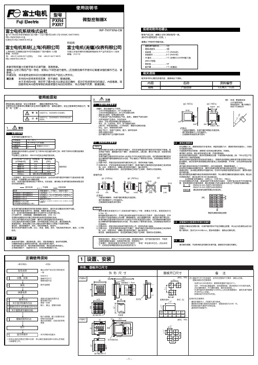
富士PXR4温控中文说明书
富 士 PXR4温控表说明书
− 1 −− 2 −注) 上段(PV)显示消失(无显示)时,请在参数DP13的设定值上加64。
2接线3使用方法(请在使用前阅读)6关于温度调节器的功能− 3 −− 4 −7为熟练使用温度调节器Modbus RTU 是modicon 公司的商标。
8请在显示异常时阅读* DC4-20mA 输入时,除使用250Ω的外置电阻外,还请作为DC1-5V 输入使用。
注1) 仅同一类型中可以变更代码。
注1) 输入精度为±0.5%FS±1digit±1°C 。
但,采用热敏电阻时,则为±1%FS±1digit 。
R 热电偶0~500°CB 热电偶0~400°C注2) 采用测温电阻时,即使低于-150°C ,也不显示LLLL 。
注3)设定低于上表的最小量程时,不能保证输入精度。
的范围内,有时由于传感器的特性,不能正确显示。
*1 微型控制器X 系列与其他机型的不同点如下表所示,请加以注意。
*2 连接计算机时,需要通信变换器。
另行准备(推荐产品) (株)RA 系统公司生产 RC-77(隔离型) http://www.ras.co.jp (株)lineeye 公司生产 SI-30A(隔离型) http://www.lineeye.co.jp (株)系统sacom 公司生产 KS485(非隔离型) http://www.sacom.co.jp 规 格电源电压:AC100(-15%)~240V(+10%)、50/60Hz 、DC/AC 24V(±10%)功耗:10VA 以下(AC100V),12VA 以下(AC220V),12VA 以下(AC/DC24V)继电器接点输出:控制输出1 1c 接点AC220V/DC30V ,3A(阻性负载)控制输出2 1a 接点AC220V/DC30V ,3A(阻性负载)SSR/SSC 驱动输出*1(电压脉冲输出):ON 时 DC24V(DC17~25V)OFF 时 DC0.5V 以下最大电流 DC20mA 以下负载电阻 850Ω以上DC4-20mA 输出:容许负载电阻 600Ω以下报警输出(最多2点):继电器接点(1a 接点) AC220V/DC30V 1A(阻性负载)加热器断线报警输出:继电器接点(1a 接点) AC220V/DC30V 1A(阻性负载)通信功能*2:RS-485接口传输方式/半双工位串行起止同步传输速度/9600bps通信协议/符合Modbus RTU 或Z-ASCII (PXR 协议)传输距离/最大500m(连接总长度)连接台数/31台数字量输入:输入点数2点 (ON 判定:DC3V 以上,OFF 判定:DC2V 以下)输入接点容量 DC5V / 2mA 输入脉冲宽度 最小0.5秒传送输出:输出精度 ±0.3%以下容许负载电阻 600Ω以下远程SV 输入:输入精度 ±0.5%FS 以下(无输入断线检测功能)设定分辨率 3000以上带输入滤波功能使用及贮存温度:-10°C ~50°C ,90%RH 以下(无结露)-10°C ~45°C(密集安装时)-20°C ~60°C(贮存温度)时间精度:±0.5%以内SSR/SSC 驱动输出DC4-20mA 输出容许负载电阻电压最大电流PXR3DC15V 20mA 100~500ΩPXR4/5/7/9DC24V 20mA 600Ω以下PXV3DC5.5V 20mA 600Ω以下PXV/W/Z DC24V 60mA 600Ω以下[所谓过量程方向]输入在范围之外或异常时的输出方向。
温控器PXR说明书
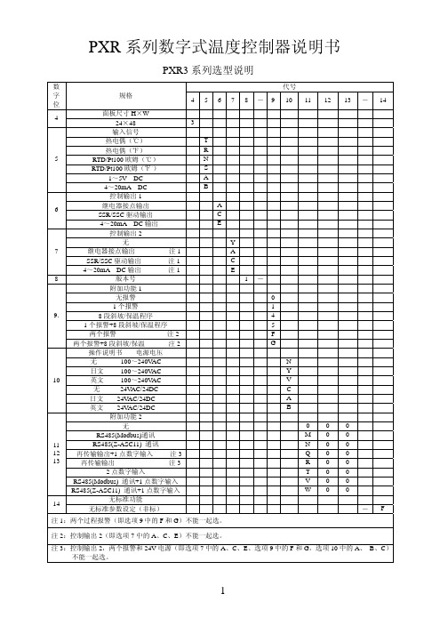
PXR 系列数字式温度控制器说明书PXR3系列选型说明 代号 数字位规格 45678-9101112 13 - 14面板尺寸H ×W 4 24×48 3 输入信号 热电偶(℃) T 热电偶(℉) R RTD/Pt100欧姆(℃) N RTD/Pt100欧姆(℉。
) S 1~5V DC A 54~20mA DC B 控制输出1 继电器接点输出 A SSR/SSC 驱动输出 C 64~20mA DC 输出 E 控制输出2 无 Y 继电器接点输出 注1 A SSR/SSC 驱动输出 注1 C 74~20mA DC 输出 注1 E 8版本号 1- 附加功能1 无报警 0 1个报警 1 8段斜坡/保温程序 4 1个报警+8段斜坡/保温程序 5 两个报警 注2 F 9.两个报警+8段斜坡/保温 注2 G 操作说明书 电源电压 无 100~240V AC N 日文 100~240V AC Y 英文 100~240V AC V 无 24V AC/24DC C 日文 24V AC/24DC A 10英文 24V AC/24DC B 附加功能2 无 0 0 0 RS485(Modbus)通讯 M 0 0 RS485(Z-ASC11) 通讯 N 0 0 再传输输出+1点数字输入 注3 Q 0 0 再传输输出 注3 R 0 0 2点数字输入 T 0 0 RS485(Modbus) 通讯+1点数字输入 V 0 0 111213RS485(Z-ASC11) 通讯+1点数字输入 W 0 0 无标准功能14 无标准参数设定(非标) - F 注1:两个过程报警(即选项9中的F 和G )不能一起选。
注2:控制输出2(即选项7中的A 、C 、E )不能一起选。
注3:控制输出2,两个报警和24V 电源(即选项7中的A 、C 、E 、选项9中的F 和G ,选项10中的A 、 B 、C )不能一起选。
PXR4系列选型说明 代号 数字位规格 45678-910 11 12 13面板尺寸W ×H 4 48×48mm 4 输入信号 热电偶(℃) T 热电偶(℉) R RTD/Pt100欧姆(℃) N RTD/Pt100欧姆(℉。
富士PXR系列温度控制器参数设定

富士PXR系列温度控制器参数设定
一、设置参数:
1.按SEL约1秒进入第一组参数表;
2.按SEL约3秒进入第二组参数表;
3.按SEL约5秒进入第三组参数表;
4.以上如持续按SEL不放,将回到原始状态;
5.进入参数模式时,如超过30秒无设定动作,显示将回到原始状态。
二、无法设定参数时,检查LOC是否锁定
锁定按键(LOC范围:0,1,2,3,4,5)
*按键锁LOC
*本功能可将控制器内部参数依不同使用程度设定。
0:所有参数均可盘面/通讯设定;
1:所有参数盘面均不可设定,只能通讯设定;
2:仅能盘面键入设定值,所有参数均可通讯设定;
3:所有参数均可盘面设定,无法通讯设定;
4:所有参数均可盘面通讯设定;
5:仅能设定设定值,所有参数均无法设定。
RC4 中文操作手册范本
手册引导内容提要1介绍1.1手册结构1.2补充文件1.3操作手册使用人群1.4手册中使用的信号和警示1.5使用的方式和缩写1.6版本附件2设备描述2.1目的2.2潜在的危险3总述3.1电源3.2外加24VDC3.3使用的电缆型号3.4安全须知3.4.1Congrav RC-4使用安全须知3.4.2安装安全须知3.4.3接线安全须知3.4.4使用和操作安全须知4硬件描述4.1Congrav RC-4:类型4.2Congrav RC-4A:显示和按键4.2.1集成按键及其功能4.2.2显示和功能组成4.3参数更改4.3.1数字输入4.3.2固定参数设置的选择4.3.3如果….,更改参数不被接受4.4Congrav RC-4B:4.5Congrav RC-4的插卡槽4.5.1现场的可能连线4.6Congrav RC-4的基本功能4.6.1插入卡RC4-MSIO4.6.1.1XS1.1:与主计算机的连接4.6.1.2XS1.2:与ISC现场总线的连接4.6.1.3XS1.3:与调试解调器和工控电脑的连接4.7Congrav RC-4的选项卡4.7.1CDIO插入卡4.7.2DIOP插入卡4.7.2.1输入输出模式-数字式RC-4的终端功能4.7.3ANOP插入卡4.7.3.1输入输出模式-模拟式RC-4的终端功能4.7.4Profibus模式5调试5.1安装5.2调试,Congrav RC-4的开机5.3Congrav RC-4:软件升级5.4ISC-CM:软件升级6菜单页F100安装结构6.1F110:安装模式6.2模拟结构6.3F120:主计算机操作6.4F130:显示内容改变6.5连锁停机6.6时间和日期6.7F150:配方处理6.7.1设定值斜线,设定值阈值6.7.2调试操作7F200:打印机结构,内存值重设7.1打印功能7.2F210:如何清除记忆内容8F300:设定值输入和选择8.1安装设定值8.2加料器设定值8.2.1`设定值的模拟控制8.2.2设定值斜线,设定值阈值(菜单页F150)8.3选项8.4F310:滞后时间8.5报警停机9F400:安装的实际值,总产量重设9.1F430:总产量重设10单台加料器操作10.1加料器页的抬头10.2Kxx0:加料器控制10.3操作功能10.3.1开机 5410.3.2停机 5410.3.3报警重设10.3.4补料 5510.3.5删除 5510.3.6开始试样10.3.7开始去皮10.3.8右侧行实际值的显示10.4Kxx1:产品参数10.4.1自动去皮10.4.2检查最大输出10.4.3堆积密度10.4.4体积最大输出10.4.5十进制转换10.4.5.1十进制转换的设置10.4.6模式 5910.4.6.1失重式加料(GF)10.4.6.2体积式控制(VR)10.4.6.3体积式设置(VS)10.4.6.4排料(DI)10.4.6.5检查最大输出(CM)10.4.6.6重量式排料(GD)10.4.6.7体积式加料(VF)10.4.6.8测量(M)10.4.6.9运行过程中GF和VF模式转换10.5Kxx2:控制参数10.5.1PID控制的设置10.5.1.1控制成套配合10.5.1.2重量式计算最大输出10.5.1.2.1CM值的存储11F500:报警报告和开机条件11.1报警报告11.2缺省的开机条件11.3系列驱动控制操作的错误代码11.3.1系列变频器11.3.2振动放大器控制器ISC-VC11.4Kxx5:报警结构12硬件结构12.1 Kxx8:ISC-CM(-A)的硬件结构12.1.1 速度输入12.1.2 传感器(重量读取)的结构12.1.3 驱动控制器12.1.4 ISC-CM-A模拟输入输出的结构12.1.4.1 ISC-CM-A上单台控制的选项12.1.4.2 Kxx8:模拟输入12.1.4.3 Kxx8:模拟输出12.2 ANOP模拟输入输出的结构12.2.1 安装控制和安装的实际值12.2.1.1 菜单页F190的参数12.2.2 ANOP的组分功能12.2.2.1 模拟输入:模拟单台控制12.2.2.2 模拟输出:总操纵量或实际值12.2.2.2.1 模拟输出信号范围的定义12.3 CDIO的数字输入输出12.4 DIOP的数字输入输出12.4.1 DIOP:功能描述12.5 ISC现场总线机构12.5.1 如果构建总线通讯12.5.2 总线通讯的关闭12.6 调试解调器的机构12.7 主计算机操作机构12.7.1 MISO卡上的主计算机接口12.7.2 Profibus DP操作结构12.7.3 以太网接口的结构13校正程序13.1加料器参数13.2加料器参数功能解释13.2.1CP02-加料范围13.2.2CP04-欠载13.2.3CP03-最大输出量13.2.4CP05-过载13.2.5CP06-粗去皮13.2.6CP07-平均重量取数13.2.7CP08-总产量累计分值13.2.8CP09-最小速度13.2.9CP010-最大速度13.2.10CP11-控制偏差13.2.11CP12-报警停机滞后时间13.2.12CP13-联锁类型13.2.13CP14-实际值指示13.2.14CP15-杠杆臂值13.2.15CP16-料斗内容13.2.16CP17-最小补料料位13.2.17CP18-最大补料料位13.2.18CP19-Window/K1/滤波IDL/F, AED 13.2.19CP20-数字速度13.2.19.1标准速度监控13.2.19.2FlexWall-Plus加料器的运动监控13.2.19.3数字式速度取数13.2.19.4推荐输入13.2.20CP21-最大补料时间13.2.21CP22-补料优化13.2.22CP23-稳定时间13.2.23CP24-测样时间13.2.24CP25-防振(AV)切断时间13.2.25CP26-PID控制器接近时间13.2.26CP27-控制器自动化13.2.26.1控制器自动化13.2.26.2开机自动化13.2.26.2.1重复的开机自动化13.2.26.2.2总体开机自动化13.2.27CP28-滤波限制13.2.28CP29-实际值的接纳13.2.29CP30-总操纵量的接纳13.2.30CP31-体积控制(VR)实际值的接纳13.2.31CP32-开机滞后时间13.2.32CP33-称重桥(LWB)的长度13.2.33CP34-重量测试值(WTV)13.2.34CP35-摄取(AP)13.2.35CP36-自动去皮范围13.2.36CP37-无负载时间自动去皮13.2.37CP38-有比例的皮带速度13.2.38CP39-皮带长度13.2.39CP40-dead time way13.3附加参数13.3.1AP01-05 校正13.3.2AP11-可用的称重范围13.3.3AP12-drop out13.3.4AP13-速度模式13.3.5AP14-滑动影响13.3.6AP15-滑动值13.3.7AP16-速度接纳性13.3.8AP17-无负载时间13.3.9AP18-AT时间13.3.10AP19-驱动控制2最小13.3.11AP20-驱动控制2最大14硬件测试功能14.1F140:输入输出测试-外围(安装)14.2Kxx3:输入输出状态显示-外围14.3Kxx4:测试功能和模拟14.3.1模拟模式14.3.2输入输出测试(加料器)15名词解释附件11915.1技术数据15.2电磁兼容性15.3零配件清单15.4可能显示的模式清单15.5菜单页清单插图表图4-1:Congrav RC-4后部视图图4-2:Congrav RC-4后部视图(带ProfiBus模式)1 总介绍1.1手册的结构现有的操作手册包括:RC-4的:●技术操作和●RC-4 HGC软件(其版本请参见封页)按照下列顺序,每章独立描述一个完整的主题:●设备的描述●使用特性●硬件执行●硬件功能定义●操作●软件描述●参数描述和●结构例举1.2附加文件●ISC系统的描述●ISC-CM,ISC-FC和ISC-VC的技术手册●相应主计算机程序手册1.3操作手册所适用的人群操作手册适用于以下两组人群:●经过授权和培训过的专业技术人员来进行安装和其它电气工作。
XRS-4 X光源操作手册说明书

XRS-4X-RAY SOURCEOPERATOR’S MANUALCONTENTSITEM PAGE1.0 INTRODUCTION (2)2.0 WARNINGS (2)DUTY CYCLE (2)3.0 PHYSICAL DESCRIPTION (3)HIGH VOLTAGE PULSER/TUBEHEAD (3)BASE (3)BATTERY PACK (3)BATTERY CHARGER (3)CONTROL MODULE (4)CABLE CONNE CTOR DIAGRAM (5)4.0 DESCRIPTION OF OPERATION (6)BLOCK DIAGRAM (6)5.0 OPERATING INSTRUCTIONS (7)OPERATING PRECAUTIONS (7)EXCLUSION ZONE (7)PULSE SELE CTION (7)REMOTE CABLE OPTION (8)DELAY MODE OPTION (8)REAL TIME IMAGING OPTION (8)PULSE SETTINGS (8)6.0 SOFTWARE (9)7.0 MAINTENANCE (9)DOSE MEASUREMENT (9)TUBE RE PLACEMENT (9)8.0 TROUBLE-SHOOTING (10)9.0 INSTRUCTIONS FOR REPAIR (10)FUSE REPLACEMENT (10)REMOVING BOARDS (10)BOARD INSTAL LATION (11)BATTE RY DISPOSAL (11)10.0 WARRANTY (13)RETURNING REPAIR INSTRUCTIO NS (13)11.0 SPECIFICATIONS (14)PHYSICAL DIMENSIONS (14)X-RAY OUTPUT (14)ELECTRICAL & THERMAL CHARACTERISTICS (14)12.0 SPAR E PARTS (14)1.0 INTRODUCTIONThe XRS-4 produces high levels of radiation and must be operated by qualified personnel who have read the Warning and Operations section of the manual before operating the device.The XRS-4 is a small, lightweight x-ray generator that operates on its own removable battery pack. The XRS-4 is a pulsed x-ray device that produces x-ray pulses of very short duration (50 nanoseconds). It produces a relatively low dose rate comparable to a 0.25 ma constant potential machine. The energy produced by the XRS-4 is up to 370KVP, which makes it possible to radiograph up to one (1.5) inch (3.81 cm) of steel.XRS-4 standard accessories are two keys, two battery packs, and one battery charger. Remote cable, carrying case, and film developing equipment are also common accessories.2.0 WARNINGSThe XRS-4 is a pulsed X-ray generator that emits hazardous ionizing radiation when pulsing. The XRS-4 should only be operated by authorized personnel who are properly trained to safely operate the generator. The XRS-4 must be registered with proper authorities prior to use and should not be used to intentionally expose humans.Develop and closely follow a safe operating system for using the XRS-4. The safe operating system must ensure that no one is exposed to radiation above the permissible limits which are 2 mR (0.02 mSv) per hour for a member of the public. The safe operating system must ensure the XRS-4 is used within federal and state guidelines.All operators and users of the XRS-4 x-ray machine must wear a personal radiation monitoring device, such as a TLD (thermo luminescent dosimeter), film badge, and/or a pocket dosimeter consistent with the appropriate federal, territorial or provincial standards (note: an electronic dosimeter will not detect the XRS-4 radiation pulses).Due to the short pulse width of the XRS-4, survey meters of the Geiger-Mueller and scintillator type do not accurately detect the radiation emitted from the x-ray source.Survey meters should be of the ionization type and should be used in the integration mode. Survey meters must not be used in the rate mode because the XRS-4 does not produce constant radiation. The XRS-4 produces very high rates of radiation for very short periods of time resulting in either unrealistically high readings or no readings for a survey meter in rate mode.The XRS-4 has no explosion proof rating and should not be used in an explosive atmosphere. The Spark Gap is vented to the air and could be a source of ignition.DUTY CYCLE WARNING.The XRS-4 is a light duty machine that is not made to pulse continuously. The maximum duty cycle for the XRS-4 is 200 pulses every four minutes (3000 pulses per hour). Two consecutive pulse trains of 99 pulses can be fired then the unit should rest at least four minutes. Exceeding the duty cycle will shorten the life of the tube and head.3.0 PHYSICAL DESCRIPTIONFigure 1: XRS-4 X-ray UnitHIGH VOLTAGE PULSER/TUBEHEAD. The main body of the XRS-4 is the tube head which contains the tube cavity, cold cathode type X-ray tube, spark gap, high voltage capacitor, and transformer. The standard collimator located on the front of the head limits the X-ray beam to 40 degrees. Special order collimators up to 85 degrees are available.BASE . The base of the XRS-4 contains the identification label and a threaded ¼-20 insert that can be attached to any standard camera tripod. Identification label indicates the model, manufacturer, and serial number is located on the bottom of the XRS-4 base.BATTERY PACK . The standard battery pack is a DeWalt 18V nickel-cadmium battery. Optional battery chemistry or voltage may be available.BATTERY CHARGER : The standard battery charger is the DeWalt DW9116 110V charger or DE9108 220V charger. Battery charge time is one hour. See battery charger manual for additional instructions and warnings.BATTERYCONTROL MODULEHANDLEBASEHEADCOLLIMATORKEYBEAM ANGLE LABELRADIATION WARNING LABEL3.5 CONTROL MODULEFigure 3: Control ModulePOWER ON LIGHT: Illuminates when battery voltage is applied to control module.RED X-RAY PULSING LIGHT: Blinks after time delay button or remote cable button is pressed to warn that the XRS-4 is going to pulse. The light stays on continuously while the XRS-4 is pulsing. This is a failsafe warning light. If the light does not work the X-ray unit will not pulse .LIQUID CRYSTAL DISPLAY (LCD): Two digit LCD displays selected pulse, time before unit pulses, software version, and total number of pulses on the unit.RANGE SWITCH: Used to alternate LCD between tens digit and ones digit.UNITS SWITCH: Used to change the value of the tens digit or units digit from 0 to 9. The UNITS SWITCH is also used with the EMERGENCY STOP SWITCH to alter the default pulse setting.DELAY SWITCH: Initiates delay mode.EMERGENCY STOP SWITCH: Stops the unit before it begins pulsing or stops the unit in the middle of a pulse train. This switch can also be pressed with the UNITS SWITCH to alter the default pulse setting when the XRS-4 is first powered up.CABLE CONNECTOR: Lemo connector located on the back of the control module beneath the battery receives the remote cable or imaging system cable. See Rear View Diagram on page 5 for details.BACK PLATE: Covers the Oscillator board and contains battery terminal connectors.XRS-4 REAR VIEW/CABLE CONNECTORREMOTE CONNECTOR: LEMO EPG.0B.305.HLN MATING CABLE PLUG: L EMO FGG.0B.305.CLAD 56Z5 432 14.0 DESCRIPTION OF OPERATIONThe block diagram below illustrates how the XRS-4 functions. The following sequence of events takes place each time the XRS-4 is fired:1. User initiates operation of the machine.2. The control section sends a signal to the converter section to begin oscillating.3. Once oscillating, the converter section changes the 18 volts DC to 22Khz AC.4. The transformer charges the High Voltage Capacitor to about 9000 volts.5. The spark gap arcs after the High Voltage Capacitor reaches proper voltage.6. The pulse detector signals the control block that the unit has pulsed.7. As the High Voltage Switch is closed, a high voltage transient of approximately 270,000 volts and50 nanoseconds in duration is applied across the x-ray tube generating x-rays.The closing of the High Voltage Switch produces an audible pulsing sound. The XRS-4 cannot produce x-rays without the pulsing sound so it serves as an additional warning the XRS-4 is functioning.This unit generates x-rays through high voltage bombardment of a tungsten target. The XRS-4 does not contain radioactive materials. All the high voltage is contained within the aluminum canister and as long as the canister is not punctured the operator is not exposed to dangerous voltages.BLOCK DIAGRAM5.0 OPERATING INSTRUCTIONSOPERATING PRECAUTIONS: The operator should always stand at least 20 feet behind the X-ray unit and clear all personnel at least 20 feet behind the unit or at least 100 ft. from the front of the unit before pulsing. The exclusion zone (below) should be a controlled area free of all personnel while X-ray pulses.Figure 4: Exclusion ZonePULSE SELECTION1. Attach a charged battery and turn on the X-ray generator.2. Press the RANGE BUTTON. The one’s digit of the LCD will blink twice and then goblank.3. Press the UNITS BUTTON to adjust the ones digit from 0 to 9.4. Press the RANGE BUTTON again and the tens digit of the LCD will blink twice and go blank.5. Press the UNITS BUTTON to change the tens digit from 0 to 9.6. Press the RANGE or UNITS BUTTON again to accept the new pulse setting.7. Both tens digit and units digit will blink to indicate acceptance of the new pulse setting. (IfRANGE or UNITS BUTTON is not selected after entering the pulse count the generator will automatically accept the entered pulse setting after six seconds).8. Press the UNITS BUTTON and EMERGENCY STOP BUTTON simultaneously to lock in pulsesetting. XRS-4 will retain locked in pulse setting until it is changed.Select ones digit Enter ones value(0-9) Enter tens value (0-9)Change pulse default(optional)DELAY MODE OPTION1. Press Green DELAY BUTTON on top of the control module.2. LCD displays 60 and X-ray begins 60 second time delay.3. Hold DELAY BUTTON down for 1.5 seconds and time delay goes from 60 to 15 seconds.4. X-ray makes audible beep and red pulsing light blinks as generator counts down to pulse.5. Audible warning and red warning light stay on while X-ray generator pulses.REMOTE CABLE OPTION1. Attach remote cable to back of control module.2. Retreat distance of the cable behind the unit.3. Press and hold down button on the end of the remote cable until generator completes pulsetrain.4. There is 5 second safety delay before generator begins pulsing. Audible beep and red pulsinglight blink.5. Audible warning and red pulsing light stay on while X-ray generator pulses.REAL TIME IMAGING OPTION1. Change pulse setting default to 99 pulses if it is not already set to 99 pulses.2. Attach imager cable to back of the control module unless using wireless option.3. Refer to imaging system operating instructions for details on pulse setting and pulsing thegenerator.4. There is no delay in this mode so the X-ray generator pulses immediately unless there is a timedelay on the imaging system.SUGGESTED PULSE SETTINGSThe chart below lists approximate pulses necessary to penetrate various materials. Settings vary greatly depending on imaging system used. Refer to imaging system instructions for moreThe following is true when using film or digital systems that generate a positive image. If the radiograph is too dark, the film is underexposed. If the radiograph is too light the film is overexposed. Underexposure can be corrected by increasing the number of pulses and/or decreasing the distance between the imaging medium and the XRS-4. Overexposure can be corrected by reducing the number of pulses and/or increasing the distance between the imaging medium and XRS-4.Underexposed Overexposed Correct exposure (pulse setting)6.0 SOFTWAREThe software program that controls the microcontroller can be identified by turning the key switch onwhile both push button switches (RANGE & UNITS) below the LCD are depressed. The LCD displaysthe software version “65”. After “65” is displayed the total number of pulses on the XRS-4 will bedisplayed in the LCD. Each digit represents 10,000 pulses. Example: If the LCD reads “04” the totalnumber of pulses on the XRS-4 is between 40,000 and 50,000 pulses. After the total number of pulsesis displayed the LCD will read “00” or the default pulse setting that was last stored on the unit.The software program is capable of determining the state of battery charge based on the time betweeneach pulse. As the battery loses charge the XRS-4 pulse rate slows, with more time between eachpulse. If there is more than 0.33 seconds between two consecutive pulses the following will occur: The XRS-4 continues the current pulse train to “00”.After the XRS-4 stops pulsing. The LCD goes back to the original pulse setting. The left and right digits blink alternately.The condition indicates a low battery.The XRS-4 will be inoperable until the key switch is turned off and on, or the battery is replaced.If there is more than one second between two consecutive pulses.The XRS-4 stops pulsing immediately and the LCD displays 00.This function prevents XRS-4 from pulsing continuously if there is a failure in detecting circuitry.This condition may indicate a low battery, electrical noise, or failure in detecting circuitry.The operator may need to replace the battery pack, turn key switch off and on, or send the XRS-4 back for repair.7.0 MAINTENANCEX-RAY DOSE MEASUREMENT Using a dosimeter, the average X-ray dose for new tube can be established.With the dosimeter located 1 foot from the front of the case and in line with the center of the beam angle label, the reading for 10 pulses should be 26 mR to 36 mR.The leakage sheet illustrates the X-ray dose and maximum allowable radiation leakage levels for each X-ray unit. A completed copy of this form accompanies each X-ray.TUBE REPLACEMENT If you have a tube replacement kit refer to instructional disk included with thekit. If you do not have a kit the unit must be sent back to Golden Engineering or an AuthorizedDistributor for tube replacement.Tube life is approximately 50,000 pulses. Under normal conditions the tube’s output will decrease slowly with use. If the tube is broken or the glass cracks the tube output willcease immediately.8.0 TROUBLESHOOTING9.0 INSTRUCTIONS FOR REPAIRFUSE REPLACEMENT Requires T-10 Torx driver & needle nose pliers.1. Remove the back plate. Remove the 5 screws in the back plate then pull the back plate off slowlymaneuvering the battery terminal connecting wires through the opening in the oscillator board.2. The 15 amp fuse is the white one inch long fuse on the left side of the oscillator board. The 2amp fuse is a small green fuse just to the right of the 15 amp fuse. See diagram on page 12.The 15 amp fuse can be removed with fingers. The 2 amp fuse may require needle nose pliers to pull it out of the board. It should be pulled in a downward direction to remove from the board. REMOVING THE BOARDS Refer to the diagram on page 12 for steps 1-4.1. Remove the back plate (see FUSE REPLACEMENT step 1). After the terminals are through theoscillator board, disconnect the red and black battery wires.2. There are three terminals on the lower left side of the oscillator board and one on the lower right.Disconnect the two blue wires, one red wire, and one green signal wire using Philips driver.3. There are three socket head cap screws holding the oscillator board in place. Two are in themiddle of the board and one is at the bottom. Remove these three screws.4. Disconnect the oscillator board from the counter board by pulling the bottom of the oscillatorboard up and away from the counter board. Disconnect the two pin white key switch connector, white three pin remote connector and black touch pad connector.5. Tilt the back of the counter board down until the LED clears the housing then pull the board out ofthe housing.6. Remove the top plate of the control module.7. The counter board is located on the bottom of the top plate.8. Disconnect the key switch connector and ribbon connector from the bottom of the counter board.BOARD INSTALLATION1. Slide counter board back into the top of the Control Module housing just below the screwreceptacles.2. Push the counter board up so LED goes through the appropriate hole in the control modulehousing.3. Connect the three white and one black connector.4. Screw the LED cover back on.5. Put the three cap screws through the oscillator board and then put the ½” offsets on the back ofthe screws.6. Plug the oscillator board back into the counter board and push it in position.7. Tighten the three screws holding the board in place.8. Insert the flat head screw in upper left corner of the oscillator board.9. Attach the two blue wires, one red wire, and green signal line.10. Reinstall the back plate.INSTRUCTIONS FOR BATTERY DISPOSAL Follow all federal, state, and local laws for disposal of nickel-cadmium batteries. Batteries may be returned to Golden Engineering for disposal.Figure 7:Oscillator BoardCounter Board10.0 WARRANTYGolden Engineering, Inc. warrants XRS-4 X-ray unit made and sold by it or its authorized representatives to be free of defects in materials and workmanship for a period of twelve (12) months from the date of shipment to the end user. Warranty does not cover maintenance required due to life. To make a claim under this limited warranty, customer must ship the entire unit (or the component believed to be defective) to Golden Engineering, post-paid. Golden Engineering, Inc. assumes no liability for units or components shipped until they are actually in the custody of Golden Engineering, Inc. Provided Golden Engineering, Inc. in its sole discretion, is satisfied that the failure is not the result of excessive use, abuse, misuse, accident, modification or improper disassembly or repair, Golden Engineering will provide parts and labor required to repair the unit. Golden Engineering reserves the right to use reconditioned and remanufactured components that meet original specifications. The unit or component will be return shipped to customer at customer's expense. THIS EXPRESS LIMITED WARRANTY IS IN LIEU OF ALL OTHER WARRANTIES AND GUARANTEES, EITHER EXPRESS OR IMPLIED OR CREATED BY OPERATION OF LAW.THE XRS-4 X-Ray Source is manufactured by:GOLDEN ENGINEERING, INC.PO BOX 185CENTERVILLE, IN 47330 USAPhone: 1-765/855-3493Fax: 1-765/855-3492WEB: RETURNING UNIT FOR REPAIRComplete the repair form at /technical.html and include a copy of the printed form with the repair. If you do not have internet access prior to sending repair theninclude a letter containing a brief description of the problem, contact name, phone number, and return address.Remove battery before shipping the unit.Accessories are not necessary with units shipped back for repair.Be sure the unit is securely packaged for shipment and wrap in plastic bag if there is an oil leak.Ship to address:Golden Engineering6364 Means Road,Centerville, IN 47330 USAPhone: 1-765-855-3493EMAIL: *****************************11.0 SPECIFICATIONS12.0 SPARE PARTS AND ACCESSORIES FOR THE XRS-4。
温控器PXR使用说明书

PXR 系列数字式温度控制器说明书PXR3系列选型说明 代号 数字位规格 45678-9101112 13 - 14面板尺寸H ×W 4 24×48 3 输入信号 热电偶(℃) T 热电偶(℉) R RTD/Pt100欧姆(℃) N RTD/Pt100欧姆(℉。
) S 1~5V DC A 54~20mA DC B 控制输出1 继电器接点输出 A SSR/SSC 驱动输出 C 64~20mA DC 输出 E 控制输出2 无 Y 继电器接点输出 注1 A SSR/SSC 驱动输出 注1 C 74~20mA DC 输出 注1 E 8版本号 1- 附加功能1 无报警 0 1个报警 1 8段斜坡/保温程序 4 1个报警+8段斜坡/保温程序 5 两个报警 注2 F 9.两个报警+8段斜坡/保温 注2 G 操作说明书 电源电压 无 100~240V AC N 日文 100~240V AC Y 英文 100~240V AC V 无 24V AC/24DC C 日文 24V AC/24DC A 10英文 24V AC/24DC B 附加功能2 无 0 0 0 RS485(Modbus)通讯 M 0 0 RS485(Z-ASC11) 通讯 N 0 0 再传输输出+1点数字输入 注3 Q 0 0 再传输输出 注3 R 0 0 2点数字输入 T 0 0 RS485(Modbus) 通讯+1点数字输入 V 0 0 111213RS485(Z-ASC11) 通讯+1点数字输入 W 0 0 无标准功能14 无标准参数设定(非标) - F 注1:两个过程报警(即选项9中的F 和G )不能一起选。
注2:控制输出2(即选项7中的A 、C 、E )不能一起选。
注3:控制输出2,两个报警和24V 电源(即选项7中的A 、C 、E 、选项9中的F 和G ,选项10中的A 、 B 、C )不能一起选。
PXR4系列选型说明 代号 数字位规格 45678-910 11 12 13面板尺寸W ×H 4 48×48mm 4 输入信号 热电偶(℃) T 热电偶(℉) R RTD/Pt100欧姆(℃) N RTD/Pt100欧姆(℉。
PURPOSECRT - 04 温控器说明书
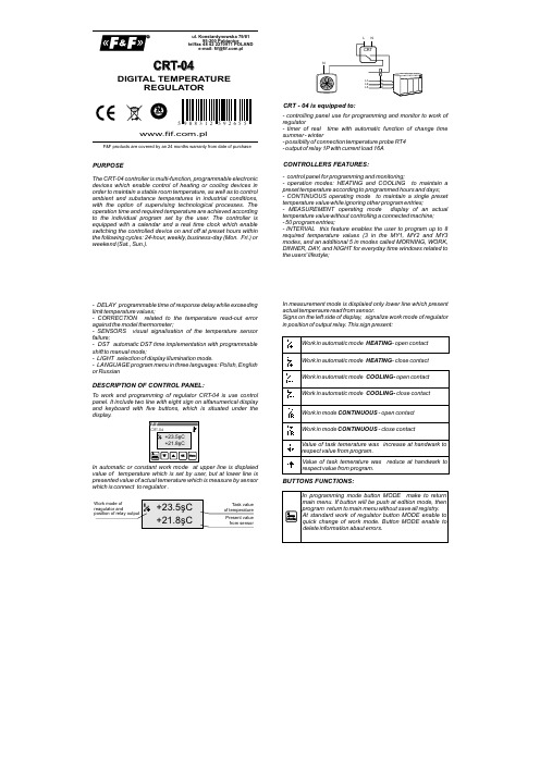
PURPOSECRT - 04 is equipped to:CONTROLLERS FEATURES:The CRT-04 controller is multi-function, programmable electronic devices which enable control of heating or cooling devices in order to maintain a stable room temperature, as well as to control ambient and substance temperatures in industrial conditions, with the option of supervising technological processes. The operation time and required temperature are achieved according to the individual program set by the user. The controller is equipped with a calendar and a real time clock which enable switching the controlled device on and off at preset hours within the following cycles: 24-hour, weekly, business-day (Mon. Fri.) or weekend (Sat., Sun.).- controlling panel use for programming and monitor to work of regulator- timer of real time with automatic function of change time summer - winter- possibilty of connection temperature probe RT4- output of relay 1P with current load 16A- control panel for programming and monitoring;- operation modes: HEATING and COOLING to maintain a preset temperature according to programmed hours and days;- CONTINUOUS operating mode to maintain a single preset temperature value while ignoring other program entries;- MEASUREMENT operating mode display of an actual temperature value without controlling a connected machine;- 50 program entries;- INTERVAL this feature enables the user to program up to 8 required temperature values (3 in the MY1, MY2 and MY3 modes, and an additional 5 in modes called MORNING, WORK, DINNER, DAY, and NIGHT for everyday time windows related to the users' lifestyle;- DELAY programmable time of response delay while exceeding limit temperature values;- CORRECTION related to the temperature read-out error against the model thermometer;- SENSORS visual signalisation of the temperature sensor failure;- DST automatic DST time implementation with programmable shift to manual mode;- LIGHT selection of display illumination mode.- LANGUAGE program menu in three languages: Polish, English or RussianCRT-04.plul. Konstantynowska 79/81tel/fax 48 42 2270971 POLANDe-mail:***********.pl95-200 PabianiceF&F products are covered by an 24 months warranty from date of purchaseDIGITAL TEMPERATUREREGULATORDESCRIPTION OF CONTROL PANEL:To work and programming of regulator CRT-04 is use control panel. It include two line with eight sign on alfanumerical display and keyboard with five buttons, which is situated under the display.In automatic or constant work mode at upper line is displaied value of temperature which is set by user, but at lower line is presented value of actual temerature which is measure by sensor which is connect to regulator .In measurement mode is displaied only lower line which present actual temperaure read from sensor.Signs on the left side of display, signalize work mode of regulator in position of output relay. This sign present:BUTTONS FUNCTIONS:In standard work mode regulator enable to make cyclic programs which wereset by user at memory. Possible is make to 50 programming registry which needed define:- day or days when will be make program. Possible is choose sibgle days( from monady to fsunday), work days, weekand and another.d- time of start program- one of eight definite by user value of task temerature (INTERVAL)FUNCTIONING:ATTENTION! Numberof program are given automaticly by regulator when the is set new program.Programs are make in chronology, it mean they start with set time and date. Stop of program is make at the moment when the nextprogram is start.EXAMPLE:The First program with temperature …morning” is execute at work days (RO) and is start at 6.00 am. The Second program with temperature …night” will be execute every day since 9 pm. The third program will be execute only weekand since 9 am. The last program with temperature “work” will be execute every Monday since 3 pm.u n d a y o u r . 0:00u n d a y ,o u r 9:00 a mo n d a y ,o u r 09:00 p mo n d a y ,o u r 06:00 a mo n d a y ,o u r 03:00 p mo n d a y o u r 09:00 p mu e s d a y ,o u r 06:00 a mu es d a y ,o u r 09:00 p me n d e s d a y ,o u r 06:00 a mExecute programATTENTION! Programs which were save at higher position are processing earlier than programs from lower position. It mean, if we have two programs with the same action and time, than will be execute program with higher number.Pass to programming mode is possible by push button MENU.Structure of main menu:PROGRAMMINGTo select position from menu we use buttons “UP” and “DOWN”. If you want pass to selected position then you need push button OK. Pass to main menu is possible by push button MENU.Menu -> MODERegulator make measurement result temperature between actual temperature from sensor C1 and task temperature Tprog. Which is set to executing program and for set width of hysteresis area H.Regulator in HEATING mode:T T P1T Regulator make measurement result temperature between actual temperature from sensor C1 and task temperature Tprog. Which is set to executing program and for set width of hysteresis area H.If temperature on input of sensor C1 fall to lower than value (Tprog H), it cause close of joint P1. Open a joint P1 will make after the temperature on input C1 will be higher than temperature (Tprog + H).Regulator in COOLING mode:T T T P1If temperature on input of sensor C1 increase to higher than value ( Tprog+ H), it cause close of joint P1. Open a joint P1 will make after the temperature on input C1 will be lower than temperature (Tprog - H).Regulator make measurement result temperature between actual temperature from sensor C1 and constant temperature Tconst, which is set by user at the moment when is select work mode and for set width of hysteresis area H.In this mode device is use only to display value of temperature.Joint P1 stay in open position.TT P1T Regulator in CONTINUOUS mode:Regulator in MEASUREMENT mode:If temperature on input of sensor C1 fall to lower than value ( Tconst H), it cause close of relay joint P1. Open of realy joint P1will make after the temperature on input C1 will be higher thantemperature (Tconst + H).Choose work mode:1. By button MENU pass to main menu of regulator.2. Push a button OK to enter pass to menu3. By buttons “UP” and “DOWN” choose work mode and enter by button OK.4. When you choose Continuous mode you should set temperature which will be hold by regulator.The first of all you set a digit of decimal position ( digit which is edit is signalize by blinking underline sign), afterwards you pass to set next position by push a button MENU. After set all digits oftask temperature enter by button OK.Menu -> ProgramOrders from menu Program make possibility to create, edit and delete programs which define behaviour of regulator in automatic work.CREATE A NEW PROGRAM:Stage of create a new program are following:1. After pass to Menu -> Program and select program- > set and enter by button OK, by buttons “UP” and “DOWN” set a minute, enter by OK and set hour for start program ( value which is edit is signalize by blinking underline minute and hour)2. Push button OK and by buttons “UP” and “DOWN” set a day when will be start program. We have following option:Monday,Tuesday,Wednesday, Thursday, Friday, Saturday, Sunday Program will be start in choosen dayProgram will be start in every work day (from Monday to Friday).Program will be start at Saturdy and Sunday Program will be start at every day of week.RO - Work days WEeekendy DO - free dayEnter selected day by button OK.3. By buttons “UP” and “DOWN” set a task temperature for present program.ATTENTION!! Possible is choose one of eight values of temperature which were definite in MENU -> interval. Everyone of values are signed by parameters: Morning, Work, Dinner, Day, Night, Mine1, Mine 2, mine 3. Changes value of temperature for present program is automaticly set for every programs with this parameter.4. Save program in memory by button OK.At any time possible is out from create new program mode, without save all registry, by button MENU.Example of create a new program:EDITION OF EXIST PROGRAM:1. After pass to menu Program need to choose option Program -> edit and enter by button OK.2. By buttons “UP” and “DOWN” select program which will be edit and enter by button OK3. Next operation are similarly as create new program.Edition of program without save all change, could break by push button MODE.DELETE PROGRAM1. After pass to menu Program need to choose option Program -> delete and enter by button OK.2. By buttons “UP” and “DOWN” select program which will be delete and enter by button OK.3. Confirm delete of program by button OK.ATTENTION! Delete program cause automaticly change numbers of rest programs.Menu -> IntervalOrdered value of temperature in programs which are make by regulator CRT-04 is not define in program code, but by group of eight parameters which comes from menu interval.If you want change value of temperature which is connect with selected parameter need to:1. After pass to menu Interval by buttons “UP” or “DOWN” select edited parameter.2. Enter by button OK.3. By buttons “UP” or “DOWN” set correct value for decimal position of degree.4. If you wont pass to edit temperature on next position, push button Menu (edit position will be signalize by blinking underline sign)5. Repeat procedure from point 3 and 4 need set all numbers with new value of ordered temperature.6. Enter all changes by button OK.Push a button any time in edit mode cause out from edition mode without save all changes.Example of set a new value of temperature:Menu -> TimerThis mode is use only for change date and time.Set a DATE:1. After pass to menu timer by buttons “UP” or “DOWN” select timer -> DATE and push button OK.2. By buttons “UP” or “DOWN” set correct month, enter OK3. By buttons “UP” or “DOWN” set correct day.Example of procedure:SET TIME:1. After pass to menu timer by buttons “UP” or “DOWN” select menu TIMER and push button OK.2. By buttons “UP” or “DOWN” select timer -> Hour and push button OK.3. By buttons “UP” or “DOWN” set correct minute, enter OK4. By buttons “UP” or “DOWN” set correct hour.5. Push button OK.. cause enter changes and start count time from set value.Example of procedure:AUTOMATIC CHANGE TIME FUNCTION:Regulator CRT-04 could automaticly change time from winter tosummer and from summer to winter. This function will be make automatic or handwork, it is set by user.If you want set function DST need to:1. After pass to menu timer by buttons “UP” or “DOWN” select function DST.2. Enter by button OK.3. By buttons “UP” or “DOWN” choose option Atomatic (if regulator have automatic change time function) or handwork (when change of time will not make).4. Enter by button OK..Menu -> SystemThis mode make possible to define additional functions of regulatorCRT-04.DELAYThis parameter make possibility to put delay of reconnection realyoutput by ordered time. In practic this function will be use at the situation when we wait for turn ON/OFF of heater, it will make when temperature go out from allow regulation area.Example with use time delay by value Tzw and regulator is presented at under picture. In this cause condition of enclose is fall a temperature under value (Tprog H) for time Tzw, but condition of excluse is increase temperature higher than value (Tprog + H) for time Tzw.T T P1T If you need set a delay time of reconnection follow procedure:1. Pass to menu -> System and by buttons “UP” or “DOWN” select option System -> Delay.2. Enter by button OK.3. By buttons “UP”and “DOWN” set value of delay.4. Enter by button OK.Push a button any time in edit parameter cause out from edition mode without save all changes.ATTENTION!: Delay time could be set in range 0 ÷ 15 min.,with step1 min.Example of setting delayHYSTERESISThis parameter make possibility to define precision and cleanliness with in will be reconnect output of relay at regulation of temperature. If value of hysteresis is smoler than precision is higher but enclose of heater component will be oftenly. But if the value of hysteresis is large that cause lower frequency of connection heater component and precision of regulation is lower.Examples characteristics with two different hysteresis areas:T T P1T S m a l l a r e a o f h y s t e r e s i sTT T L a r g e a r e a o f h y s t e r e s i sIf you need set value of hysteresis follow with procedure:1. Pass to Menu -> System and by buttons “UP” or “DOWN” select option -> Hyst.2. Enter by button OK.3. By buttons “UP” or “DOWN” set value of hysteresis.4. Enter by push button OK.At any time possible is out from edit parameter mode, without save all registry, by push button MENU.ATTENTION: Hysteresis could be set in range 0÷10°C, with step 0,1°C.Example of setting hysteresis:CORRECTIONThis parameter is use for correction indication from sensor. To set correction indication of sensor follow the procedure:1. Pass to Menu -> System and by buttons “UP” or “DOWN” select option System -> Correction2. Enter by button OK.3. By buttons “UP” or “DOWN” set value of correction.4. Enter by button OK.At any time possible is out from edit parameter mode, withoutsave all registry, by push button MODE.ATTENTION ! Correction of sensor indication could set in range 5.0 ÷ 5.0 °C, with step 0,1°C.Example of setting temperature correction:SELECT REPORT LANGUAGEThis parameter make possiblity to choose on of three language in which will be display reports. If you need change language you need pass to menu System -> Language by buttons “UP” or “DOWN” select language and enter by button OK. Return to main menu is possible by push button MODE.LIGHTING OF DISPLAYThis parameter make possibility to lighting a display of regulator. Possible is set lighting for all the time for display or lighting only for some second after push any buttonIf you need way of lighting you need to pass menu System -> Light and select by buttons “UP” or “DOWN” correct option and enter by button OK.. Return to main menu is possible by push button MODE.REATURN TO DEFAULT SETTINGSDefault settings make possibility to return all settings of regulator to target values. If you need restore default settings pass to menu System -> default settings and enter by button OK. Next by buttons “UP” or “DOWN” set value YES and push button OK.ATTENTION! Return to default settings cause delete all earlier configurations with saved programs.Rest of parameters of regulators are set with values:ModeHandwork Tzad (handwork)25,0°C Hysteresis0,0°C Delay0min Sensor correction0,0°C Correction of odered value0,0°CInterval20,0°C (everyone)Lighting of displayAll time DST AutomaticDate / Time01.01.2008 00:00QUICK CONFIGURATIONRegulator CRT-04 make possibility choose work mode and change value of order temperature without pass to programming mode.QUICK CHANGE VALUE OF WORK TEMPERATUREIf you need change work mode in standard work you need push button MODE, next follow with instructions as select work mode which is presented in programming mode section.QUICK CHANGE OF ODERED VALUETo change ordered value of temperature in standard work of regulator use buttons “UP” or “DOWN”. Pushing once time button “UP” cause increase ordered temperature by 0,5°C, but pushing button “DOWN” cause fall ordered temperature by 0,5°C. Increas temperature higher than default value is siganlize by display in upper line a sign , but fall temperature is siganlize by sign .ATTENTION!Handwork correction of ordered temperature will be force at all next work in automatic mode. Also after start program to next step of program, forced value will be change by value from handwork correction Return to deafult settins is possible in causes:- hadwork configuration to moment when arrow will disappear from display.- reconnection regulator to continuous work mode.,Example of quick configuration of ordered temperatureDISPLAY ACTUAL DATE AND TIMEDisplay to date and time, need to in standard work of regulatorpush button OK..ERRORS SYGNALINGAfter 3 sec. regulator return to earlier window.In the cause break or wrong work of sensor, regulator displayunderline report :In this cause first of all need to check connection of sensor.sensor DS18S20dimensions of sensorŘ5LiYY 3×0,34mm˛ l=2,5m; h=30mmsensor isolationtherm jacketcablePROBE RT4TECHNICAL DATAASSEMBLY:supply230V ACcurrent load<16Ajoint separated 1Prange of regulation temperature0÷60°Chysteresis setting range 0÷10°Cprecision 0,1°Cmodel correction±5°Cdelay reconnection- to set1÷15minpower consumption1,5Wworking temperature-20÷40°Cterminal screw terminals 2,5mm²dimensions 3 modules (52,5mm)fixing on rail TH-351. Take OFF the power.2. Regulator put on the rail in the switchgearbox.3. Connect supply: L to joint 1; N to joint 2.4 Out cable of temperature probe connect to realy with marksWHITE cable(7) to joint 8, BROWN cable (9) to joint 9 .5. System of enclose receiver connect in line to joints 11-126. Set program to regulation temperature.For use seprtated reconnection of joint 1P, were accept ininstruction configuration:ATTENTION!CRT-047WGB R89111210WIRING DIAGRAMATTENTION!Do not any change in device. It impend break or wrong work ofdevice, it will cause break contolled device or menace for user. Inthis cause producer is not responsible of arise accidents andcould refuse given warranty for regulator in cause submit a claim.A090701。
PXR 系列数字温度控制器

PXW5 (conve ntional )
PXR4
New model
PXR5
New model
PXR series digital controller
前面防水机能: IP66/NEMA-4X
• 防水机能构造可以提供面板上的PXR以抗水洗能 力!
• 防水机能作为一种标准,所以客户无需在 增加任何费用!
可追加技能VII: 广泛的报警输出
• 可选择1,2,3点报警输出 • 使用按键可以在15种警报中选 择
– 绝对值警报 – 偏差值警报 – 范围警报
PXR series digital controller
插入式PCB构造以节省零件 以便维护
• 3块插入式PCB板可提供超过2000零件:
– PCB I: 主PCB板以及第1控制输出 – PCB II: 电源以及警报输出 – PCB III: 可追加PCB班,第2控制输出, 对应多种输入
PV retransmission
Temperature input (PV)
Fryer
Recorder
Control output Oil
Auto power regulator
Heater
PXR series digital controller
可追加技能II: 8 段 ramp soak 机能
报警机能
2 points(at max.)
• PXR 系列
6 + 5 + 7 = 18 种!!
PXR series digital controller
插入式结构以减少零件 更便于维护
• PCB I: Main PCB ① T/C or RTD input