WEST-8100+温控器说明书
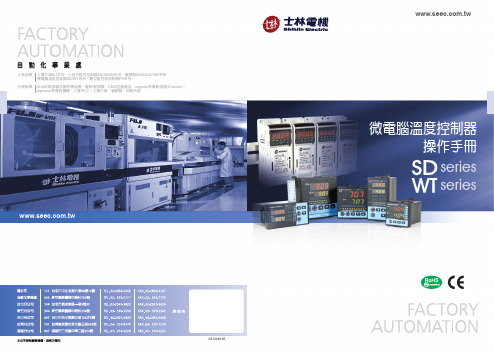
士林_温控器操作手册
22
9.2 Level2 (PID 層)
8.2.1
參數“顯示/隱藏”條件 .....................................................
23
8.2.2
參數說明 ......................................................................
41
15.2 軟體部分 .................................................................................................
42
16 更改輸出類型 : Relay , SSR , 4~20mA ............................................................ 43
7
2.4 安裝及配線......................................................................................
8
2.5 操作說明..........................................................................................
17
7 操作步驟說明
7.1 開機 ...............................................................................................
18
7.2 設定 SV ..........................................................................................
温控器说明书
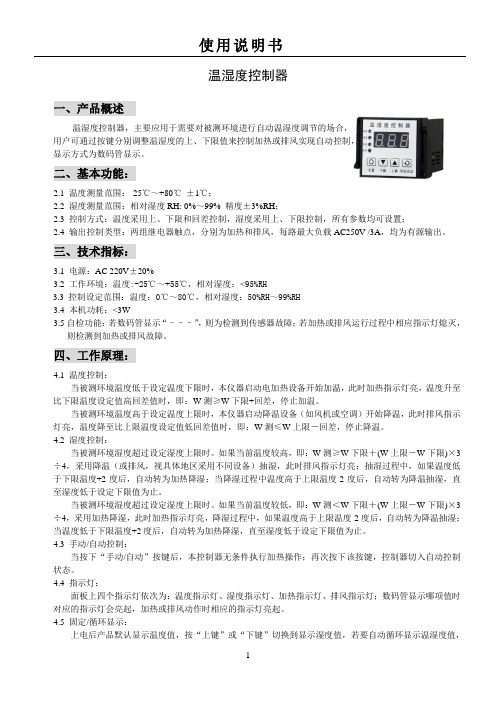
温湿度控制器一、产品概述温湿度控制器,主要应用于需要对被测环境进行自动温湿度调节的场合,用户可通过按键分别调整温湿度的上、下限值来控制加热或排风实现自动控制,显示方式为数码管显示。
二、基本功能:2.1 温度测量范围:-25℃~+80℃±1℃;2.2 湿度测量范围:相对湿度RH: 0%~99% 精度±3%RH;2.3 控制方式:温度采用上、下限和回差控制,湿度采用上、下限控制,所有参数均可设置;2.4 输出控制类型:两组继电器触点,分别为加热和排风,每路最大负载AC250V /3A,均为有源输出。
三、技术指标:3.1电源:AC 220V±20%3.2 工作环境:温度:-25℃~+55℃,相对湿度:<95%RH3.3控制设定范围:温度:0℃~80℃,相对湿度:50%RH~99%RH3.4 本机功耗:<3W3.5自检功能:若数码管显示“–––”,则为检测到传感器故障;若加热或排风运行过程中相应指示灯熄灭,则检测到加热或排风故障。
四、工作原理:4.1 温度控制:当被测环境温度低于设定温度下限时,本仪器启动电加热设备开始加温,此时加热指示灯亮,温度升至比下限温度设定值高回差值时,即:W测≥W下限+回差,停止加温。
当被测环境温度高于设定温度上限时,本仪器启动降温设备(如风机或空调)开始降温,此时排风指示灯亮,温度降至比上限温度设定值低回差值时,即:W测≤W上限-回差,停止降温。
4.2 湿度控制:当被测环境湿度超过设定湿度上限时。
如果当前温度较高,即:W测≥W下限+(W上限-W下限)×3÷4,采用降温(或排风,视具体地区采用不同设备)抽湿,此时排风指示灯亮;抽湿过程中,如果温度低于下限温度+2度后,自动转为加热降湿;当降湿过程中温度高于上限温度-2度后,自动转为降温抽湿,直至湿度低于设定下限值为止。
当被测环境湿度超过设定湿度上限时。
如果当前温度较低,即:W测<W下限+(W上限-W下限)×3÷4,采用加热降湿,此时加热指示灯亮,降湿过程中,如果温度高于上限温度-2度后,自动转为降温抽湿;当温度低于下限温度+2度后,自动转为加热降湿,直至湿度低于设定下限值为止。
温控器说明书
温湿度控制器一、产品概述温湿度控制器,主要应用于需要对被测环境进行自动温湿度调节的场合,用户可通过按键分别调整温湿度的上、下限值来控制加热或排风实现自动控制,显示方式为数码管显示。
二、基本功能:2.1 温度测量范围:-25℃~+80℃±1℃;2.2 湿度测量范围:相对湿度RH: 0%~99% 精度±3%RH;2.3 控制方式:温度采用上、下限和回差控制,湿度采用上、下限控制,所有参数均可设置;2.4 输出控制类型:两组继电器触点,分别为加热和排风,每路最大负载AC250V /3A,均为有源输出。
三、技术指标:3.1电源:AC 220V±20%3.2 工作环境:温度:-25℃~+55℃,相对湿度:<95%RH3.3控制设定范围:温度:0℃~80℃,相对湿度:50%RH~99%RH3.4 本机功耗:<3W3.5自检功能:若数码管显示“–––”,则为检测到传感器故障;若加热或排风运行过程中相应指示灯熄灭,则检测到加热或排风故障。
四、工作原理:4.1 温度控制:当被测环境温度低于设定温度下限时,本仪器启动电加热设备开始加温,此时加热指示灯亮,温度升至比下限温度设定值高回差值时,即:W测≥W下限+回差,停止加温。
当被测环境温度高于设定温度上限时,本仪器启动降温设备(如风机或空调)开始降温,此时排风指示灯亮,温度降至比上限温度设定值低回差值时,即:W测≤W上限-回差,停止降温。
4.2 湿度控制:当被测环境湿度超过设定湿度上限时。
如果当前温度较高,即:W测≥W下限+(W上限-W下限)×3÷4,采用降温(或排风,视具体地区采用不同设备)抽湿,此时排风指示灯亮;抽湿过程中,如果温度低于下限温度+2度后,自动转为加热降湿;当降湿过程中温度高于上限温度-2度后,自动转为降温抽湿,直至湿度低于设定下限值为止。
当被测环境湿度超过设定湿度上限时。
如果当前温度较低,即:W测<W下限+(W上限-W下限)×3÷4,采用加热降湿,此时加热指示灯亮,降湿过程中,如果温度高于上限温度-2度后,自动转为降温抽湿;当温度低于下限温度+2度后,自动转为加热降湿,直至湿度低于设定下限值为止。
WEST表P8100用户手册(0-10V)
7.1.1
进入选择模式 ........................................................................................... 24
7.1.2
操作指南 ..................................................................................................24
4.27 输出 3 - 继电器........................................................19
4.28 输出 3 - SSR 驱动 .....................................................19
4.29 输出 3 – 线性直流 .....................................................20
注意: 在仪表接线端子处有此警告标志,在仪表接线时请仔细阅读本手册 本手册使用产品型号: P4100, P6100 & P8100
ii
Danaher Sensors & Controls
1/4 -DIN, 1/8 -DIN & 1/16 -DIN 控制器、显示仪和程序控制器手册
目录
目录...................................................................................................................................... iii 如何使用本手册 ..................................................................................................................... 1 1 简介..............................................................................................................................2 2 安装..............................................................................................................................3
CN8100系列温度控制器说明书
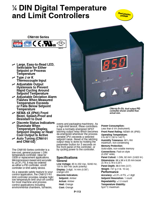
U L arge, Easy-to-Read LED, Selectable for EitherSetpoint or ProcessTemperatureU T ype J or KThermocouple InputU A djustable O utputHysteresis to PreventRapid Cycling AroundSetpoint TemperatureU A djustable Deviation Alarm Flashes When MeasuredTemperature Exceedsor Falls Below SetpointTemperatureU N EMA 4X (IP65) FrontBezel, Splash-Proof andResistant to DustU D iscrete Status Indicators Illuminate WhenTemperature Display,Setpoint Display or Heat/Cool Output Is ActiveU A uto Tuning (CN8101and CN8102)CN8100 SeriesThe CN8100 Series controller is alow-cost, general purpose 1⁄4 DINtemperature controller, ideal for OEM or replacement applications. Microprocessor-based and accurate to ±0.3% FS, it may be orderedas either a PID controller, on/off controller or limit safety device.As a separate safety feature to your control application, the CN8121-R1 limit controller provides reliable high/ low temperature limit shut-off control for most machine and process control applications including environmental chambers, furnaces, SpecificationsGeneralLine Voltage: 85 to 250 Vac, 50/60 Hz,120 to 300 Vdc (auto polarity)Display: 3-digit, 14 mm (0.56")orange LEDDiscrete Indicators:Setpoint: AmberActual: AmberHeat: OrangeCool: OrangeCN8102-R1-R2, dual output PIDcontroller shown smaller thanactual size.Power Consumption:Less than 6 VA (instrument)Front Panel Rating: NEMA 4X (IP65)Operating Temperature:0 to 60°C (32 to 140°F)Humidity Tolerance: 90% RHmaximum, non-condensingMemory Protection:Solid-state, non-volatile memoryConnections: Fast-on style(0.250" wide)Panel Cutout:1⁄4 DIN, 92 mm2 (3.622 in2)Dimensions: 96 x 96 x 6.35 mm bezel(3.78 x 3.78 x 0.25")Panel Depth: 88.9 mm (3.5")Weight: 737 g (1 lb. 10 oz)PerformanceAccuracy: ±0.3% of FS, ±1 digitSetpoint Resolution: 1 countRepeatability: ±1.0 countTemperature Stability:5µV/°C maximumovens and packaging machinery. Asa high-limit device, these controllershave a normally energized SPSTlatching output relay which becomesde-energized whenever the processvariable (PV) exceeds a selectedsetpoint value. Reset of the latchingoutput relay is done by holding theparameter button for 3 seconds onthe front panel of the controller, orby cycling power to the controller.1⁄4 DIN Digital Temperature and Limit ControllersP a n e l p u n c h es a v a i l a b l e* Specify output type from Output Options table.Ordering Examples: CN8102-R1-R2, 1⁄4 DIN dual mechanical relay output PID controller.OCW-3, OMEGACARE SM extends standard 2-year warranty to a total of 5 years.CN8121-R1.Controllers shownsmaller than actual size.CN8102-R1-R2.CN8111-R1.TC Cold End Tracking: ±0.05°C/ °C ambientNoise Rejection: Common mode >100 dB, Series mode >70 dBProcess Sampling: 3.7 Hz (270 ms)Available Inputs: Thermocouple: CN8110: Type J CN8120: Type J CN8100: Type J or K Maximum lead resistance, 100 Ω for rated accuracy Control Characteristics:Control Hysteresis: 1 to 140°C (2 to 252°F)Display Offset: -70 to 70°C (-126 to 126°F)Deviation Alarm: Off, 1 to 140°C (Off, 1 to 252°F)Outputs: Electromechanical relay, 5 A @ 250 Vac, 5 A @ 30 Vdc, solid-state relay, 120/240 Vac, 0 voltage switched, 2 A continuous (output 1), 0.5 A continuous (output 2) 10 A surge @ 25°C (77°F), pulsed DC 5V for external SSROMEGACARE SMextended warranty program is available for models shown on this page. Ask your sales representative for full details when placing an order. OMEGACARE SMcovers parts, labor and equivalent loaners.。
温控器说明书

说明书设计题目温控器设计姓名:张龙学号:2011071128专业:机械工程及自动化目录摘要 (3)1 设计内容与设计要求 (4)2、方案选择 (4)2.1 单片机的选择方案 (4)2.2显示器的选择方案 (4)2.3 模数转换芯片的选择 (5)3、元器件介绍 (5)3.1 AT89C51 (5)3.2 LCD1602液晶屏 (6)3.3 ADC0804 (8)3.4 NPN型三极管 (9)4.系统硬件设计 (10)4.1时钟电路 (11)4.2 复位电路 (12)4.3 ADC转换电路 (14)4.4 LCD1602液晶显示器 (14)4.5 独立按键控制电路 (15)4.6 继电器控制电路 (15)5.软件设计 (16)总结 (17)摘要温控器(Thermostat),根据工作环境的温度变化,在开关内部发生物理形变,从而产生某些特殊效应,产生导通或者断开动作的一系列自动控制元件,也叫温控开关、温度保护器、温度控制器,简称温控器。
或是通过温度保护器将温度传到温度控制器,温度控制器发出开关命令,从而控制设备的运行以达到理想的温度及节能效果,其应用范围非常广泛,根据不同种类的温控器应用在家电、电机、制冷或制热等众多产品中。
其工作原理是通过温度传感器对环境温度自动进行采样、即时监控,当环境温度高于控制设定上限值时控制电路启动,温度下降。
当环境温度低于控制设定下限值时,控制电路不工作,温度上升。
主要应用于电力部门使用的各种高低压开关柜、干式变压器、箱式变电站及其他相关的温度使用领域。
关键词:温控器温度采样上限值下限值1 设计内容与设计要求基本内容:设计一个简易温控器基本要求:①可以设定上限温度和下限温度,温度高于上限温度上,主电路不工作,温度降低,温度低于下限控制电路时,主电路继续工作,温度升高。
③设定温度时,液晶屏上显示设定状态,设定完显示正常模式,并且设定的上下限温度,在液晶屏上都有显示。
⑤采集温度信号,转换成数字信号。
013 8100、8200控制屏说明
Logo
8120控制屏说明
主控制器为BE24控制器
科泰电源设备(上海)有限公司
COOLTECH POWER(SHANGHAI)LTD.
Logo
8120控制屏说明
主控制器参量信息
1、低燃油液位报警指示 2、紧急停机报警指示 3、低油压停机报警指示 4、高水温停机报警指示 5、电池电压值 6、皮带断裂/充电发电机故障报警指示 7、超/低频率停机报警指示 8、启动失败停机报警指示 9、交流发电机故障
科泰电源设备(上海)有限公司
COOLTECH POWER(SHANGHAI)LTD.
Logo
8100控制屏说明 8100控制屏(501K) 8100控制屏(501K)电路原理 控制屏
科泰电源设备(上海)有限公司
COOLTECH POWER(SHANGHAI)LTD.
Logo
8120控制屏说明
二、8120控制屏说明 8120控制屏说明
Logo
8100、8120、8200、8220控制屏说明 8100、8120、8200、8220控制屏说明
科泰电源设备(上海)有限公司
—销售服务中心
版本编号:VO.0801-13
Logo
8100、8200控制屏说明 8100、8200控制屏说明 目 录 1、8100控制屏说明 2、8120控制屏说明 3、8200控制屏说明 4、8220控制屏说明 5、KX系列ATS
科泰电源设备(上海)有限公司
COOLTECH POWER(SHANGHAI)LTD.
Logo
8120控制屏说明
控制屏外面板 1.主控制器:整个系统的主控制器; 2.微型空气开关:控制线路过流及短路保护; 3.紧急停机按钮
3
海洛斯操作手册(说明书)
HIROSS恒温恒湿机房精密空调操作手册HIMOD系列北京****科技有限公司技术部2009年01月01日目录第一章HIMOD系列海洛斯空调概述 (2)型号多 (3)控制技术先进 (3)制冷系统 (3)送风系统 (3)加湿系统 (3)加热系统 (4)1.7其它 (4)第二章HIMOD系列海洛斯空调型号含义 (4)第三章有关空调的一些资料 (5)气流组织方式(详见下图) (5)盖板纽开启方式(详见下图) (5)空调重量(单位:Kg) (5)机组尺寸及维护空间 (6)第四章制冷循环管路示意图 (7)风冷却(A型) (7)水冷却(W型) (8)双冷源(D型) (9)单系统(C型) (10)双系统(C型) (10)第五章调速风机调速接线示意图 (11)第六章MICROF ACE概述 (12)概述 (12)面板简介液晶显示屏 (13)液晶显示屏介绍 (13)第七章MICROF ACE面板的操作 (13)第八章控制器的使用 (14)控制器(HIROMATIC)概述 (14)控制器的操作 (15)菜单结构 (17)第九章日常维护及特殊维护 (18)日常维护 (18)特殊维护 (19)第十章常见报警及处理 (20)低压报警 (20)高压报警 (21)加湿报警 (21)失风报警 (21)电加热过热报警 (22)显示器发黑 (22)空调不制冷 (22)附录1:参数列表 (22)附录2:报警内容列表 (26)附录3:各菜单项含义: (28)第一章HIMOD系列海洛斯空调概述HIMOD系列海洛斯空调(HIMOD空调)是当今世界上最先进的机房专用恒温恒湿机房专用精密空调。
随着IT业的突飞猛进的发展,各种布局、面积差别很大的机房如雨后春笋般纷纷出现了,使用环境也不一而同。
为适应各种不同要求的机房,新开发的海洛斯HIMOD系列空调应运而生。
她是在保留她的前一代产品HIRANGE系列机房空调的优点,又应用了当今世界上提高了的制冷技术及制冷部件制造工艺,使用当今最先进的模块化设计理念生产出来的高科技机房空调产品。
WEST8100温控表选型手册
技术指标
特点 控制类型 自动/手动 输出配置 报警类型 人机界面 计算机组态
输入 热电偶 RTD DC 直流 阻抗 精度 采样频率 传感器断路检测
输出和选件 控制和报警继电器 SSR 输出 故态继电器输出 直流输出 变送器电源 通讯 数字输入 遥控输入
操作环境 温度和湿度 电源 前面板防护 认证
PID 控制,on/off 控制,自整定、自适应,单输出或加热/制冷双输出。 无扰动切换,通过按键或数字输入切换。 最多 3 个输出,可以自由设置输出用途(控制、报警、变送输出、变送器电源)。 过程高/低报警,偏差报警,,带报警,逻辑与/或报警,回路断线报警。 4 键操作, 双 4 位 10mm、8mm LED 显示, 5 个 LED 指示灯 离线计算机组态 (不需通讯选件),组态软件:PS1-CON。
选件 B
零件号
遥控输入及数字输入...............PB1-W0R
选件 B
0
无
R
遥控输入/数字输入
显示颜色
0
红色/红色
1
绿色/绿色
2
红色/绿色
3
绿色/红色
电源
0
100-240V AC
2
24-48V AC/DC
选件 A
0
无
1
RS485 通讯
3
数字输入
4
遥控输入(基本型)
选件 3
0
无
1
继电器
2
选件 1
零件号
继电器模块 ..............................PO1-C10
直流模块.................................. PO1-C21
SCD8000 8100温度控制器用户手册说明书
SCD8000/8100 Temperature ControllerInstruction SheetThank you very much for choosing SCD8000/8100 series temperature controller. Please read this instruction sheet carefully before using your SCD8000/8100 to ensure proper operation. Keep this instruction sheet handy for quick reference.!1Precaution!DANGER! CAUTION! ELECTRIC SHOCK!SCD8000/8100 is an OPEN-TYPE device and therefore should be installed in an enclosure free of airborne dust, humidity, electric shock and vibration. The enclosure should prevent non-maintenance staff from operating the device (e.g. key or specific tools are required for opening the enclosure) in case danger and damage on the device may occur .1. Prevent dust or metallic debris from falling into the device and cause malfunctions. DO NOT modify or uninstall the circuitboard of SCD8000/8100 without being permitted. DO NOT use empty terminals. 2. Keep away from high-voltage and high-frequency environment during the installation in case of interference. Prevent usingthe device in premises which contain:(a) dust or corrosive gas; (b) high humidity and high radiation; (c) shock and vibration. 3. The power has to be switched off when wiring or changing the temperature sensor.4. When installing the circuit board of the accessory, please make sure the power of the main unit is switched off and insertthe accessory into the correct slot on the main unit. 5. Make sure to use compensation wire which matches the thermocouple or platinum resistance when extending orconnecting the thermocouple or platinum resistance.6. Keep the wire as short as possible when wiring a sensor to the controller. Separate the power cable and load wire in orderto prevent interference and induced noise. 7. Make sure the power cables and signal device are installed correctly before switching on the power; otherwise seriousdamage may occur. 8. DO NOT touch the terminal or repair the device when the power is on; otherwise an electric shock may occur.9. Please wait for 1 minute after the power is switched off to allow the capacitor to discharge and DO NOT touch the internalwiring within this period. 10. DO NOT touch the internal terminal when SCD8000/8100 is either switched on or off in case you may damage the circuit. 11. Please place SCD8000/8100 with other heating objects (e.g. power supply) within proper distance while installingSCD8000/8100.2Power input DC 24V, isolated switching power supply Voltage range 90% ~ 110% rated voltagePower consumption Max. 10W + 3W × number of SCD2000 controllers connected in parallel (Max. 7) Thermocouple: K, J, T, E, N, R, S, B, L, U, TXK Input sensor Platinum resistance: Pt100, JPt100, Cu50Sampling cycle Thermocouple or platinum resistance: 1.0 second/all input Control method PID, PID programmable, manual, ON/OFFRelay output: SPST, Max. AC 250V load, 3A resistive load Voltage pulse output: DC 24V, Max. 40mA current outputCurrent output: DC 4 ~ 20mA output (resistive load < 500Ω); for OUT1 and OUT2 only Output accessories (optional)Analog voltage output: 0 ~ 10V (resistive load > 1,000Ω); for OUT1 and OUT2 onlyOutput functions Control output, alarm output or proportional output (proportional output is only applicable in themodel with linear voltage and current output for OUT1, OUT2) Alarm modes12 alarm modes availableCommunicationRS-485 digital communication; supports baud rate 2,400bps ~ 115,200bps Communication protocol Supports Modbus ASCII/RTUExtension port The extension port transmits 24V power supply and communication signals to extension module SCD2000.Vibration resistance 10 ~ 55Hz 10m/s 23 axes 10minsShock resistance Max. 300m/s 23 axes 6 directions, 3 times each Ambient temperature 0°C ~ +50°C Storage temperature -20°C ~ +65°C Operation altitude < 2,000mAmbient humidity 35% to 85% RH (non-condensing) Pollution degree23SCD8000/81001 I/O terminals2 Status LED 3Display and setup unit4 DIN rail clip5 Power input port6 RS-485 communication port 7Extension module fixing clip8 Extension port4 Panel Layout5InputThe standard SCD8000/8100 main unit is attached with 4 channels of inputs. You can purchase additional SCD-4T or SCD-4Rto expand the number of input channels. SCD8000/8100 supports maximum 8 channels of inputs which belong to group INA and group INB. Each group possesses 4 input channels. SCD8000/8100 series supports the following input sensors:Input Sensor TypeRegister ValueRangeFor SCD8100 / SCD-4RTemperature measurement resistance (Cu50)13 -50 ~ 150°C Platinum resistance (Pt100)12 -200 ~ 600°C Platinum resistance (JPt100) 11-20 ~ 400°C For SCD8000 / SCD-4TThermocouple TXK type 10-200 ~ 800°C Thermocouple U type 9 -200 ~ 500°C Thermocouple L type 8 -200 ~ 850°C Thermocouple B type 7 100 ~ 1,800°C Thermocouple S type 6 0 ~ 1,700°C Thermocouple R type 5 0 ~ 1,700°C Thermocouple N type 4 -200 ~ 1,300°C Thermocouple E type 3 0 ~ 600°C Thermocouple T type 2 -200 ~ 400°C Thermocouple J type 1 -100 ~ 1,200°C Thermocouple K type-200 ~ 1,300°CNote: The default setting in SCD8000 is “thermocouple K type”. The default setting in SCD8100 is “Pt100".Communication address: Input sensor types at H10A0 ~ H10A7; input upper limits at H1010 ~ H1017; input lower limits atH1018 ~ H101F.6OutputSCD8000/8100 supports maximum 16 channels of outputs, belonging to output groups OUT1, OUT2, SUB1 and SUB2, each group with 4 channels. See the explanations below for how input channels correspond to output groups.Without group INB (4 channels of input): Every channel corresponds to 2 groups of output and 2 groups of alarms. OUT1 and SUB1 are for control output, and OUT1 can be used for proportional output. OUT2 and SUB2 are fixed for alarm output. With group INB (8 channels of input): Every channel is paired with 2 groups of outputs. OUT1 and OUT2 are used for control output or proportional output of CH1 ~ CH8. SUB1 and SUB2 are used for control output or alarm output. See Table 1 for the relations between input and output.4 channels of input 8 channels of inputOutput GroupINA (CH1 ~ CH4)INA (CH1 ~ CH4)INB (CH5 ~ CH8) OUT1 Main control output or proportional output Main control output or proportionaloutputNo corresponding output OUT2 Alarm 1 output No corresponding output Main control output or proportionaloutputSUB1 Control output Control output or alarm output No corresponding output SUB2Alarm 2 outputNo corresponding output Control output or alarm outputTable 1Note: SUB1 and SUB2 do not support SCD-46 and SCD-45. Please install the optional output modules you purchase intothe correct slot.Communication Address of Output & How to Set up Parameters:See Table 2 for the communication addresses of output and Table 3 for the definition of the value in the address. INAINBCH1 CH2 CH3 CH4 CH5 CH6 CH7 CH8 OUT1, OUT2 H10A8 H10A9 H10AA H10AB H10AC H10AD H10AE H10AF SUB1, SUB2H10B0H10B1H10B2H10B3H10B4H10B5H10B6H10B7Table 2Value = 0Value = 1 Value = 2 Value = 3 OUT1, OUT2** Heating control Cooling control Proportional output Disable output SUB1, SUB2**Heating controlCooling controlAlarm output*Disable outputTable 3*When there are only 4 channels of inputs, SUB1 cannot be used for alarm output but heating/cooling control only.**When there are only 4 channels of inputs, OUT2 and SUB2 cannot be set up by the user but set up automatically as "alarmoutput” by the controller. Control Output:SCD8000/8100 offers PID control, ON/OFF control, manual control and programmable PID control. Control output methods are set at address H10B8 ~ H10BF (default = 0: PID), PID parameters at H1028 ~ H105F, ON/OFF parameters at H1058 ~ H106F, and manual control parameters at H1070 ~ H107F. Alarm Output:SCD8000/8100 offers 12 alarm modes. The alarm modes are set up at address H10C0 ~ H10C7, upper limits at H1080 ~ H1087 and lower limits at H1088 ~ H108F.7LED DisplayPWR: On B SCD8000/8100 is powered. RUN: On B Any of the channel is executing. COM: Flashing B Communication in progress ERR: Indicating errors (red)ERR LED is on indicates one of the following errors occur, and the output has to be disabled. 1. Memory EEPROM error.2. Any of the input points is not connected.3. Any of the input points exceeds the setup range.4. Any of the input temperatures has not been stabilized.8Synchronous Communication Protocol & Auto ID SetupThis function allows the auto setup of communication protocol in extension module SCD2000 following the communicationprotocol set in the SCD8000 main unit. The station IDs of SCD2000 decrease. See below for the steps. 1. Set the auto communication ID of SCD8000 as “1” (communication address: H10F8).2. Switch off SCD8000. Connect SCD8000 with extension module SCD2000 and switch on SCD8000 again.3. Default communication protocol: 9,600bps, 7 bits, Even, 1 stop bit, communication address = 01.4. This function will consume 3 ~ 5 seconds more when you switch on SCD8000.9RS-485 Communication1. SCD8000/8100 supports baud rates 2,400/4,800/9,600/19,200/38,400/57,600/115,200 bps and does not supportcommunication format 7, N, 1/8, E, 2/8, O, 2. Communication protocol = Modbus ASCII or RTU. 2. Function codes: H03 = read maximum 8 words in the register; H06 = write 1 word into the register.3. Address and contents: Every parameter has 2 communication addresses. One is numbered by the function of the parameter, and the other is by the order of channel (as shown in the table below).Content Explanation CH1 CH2 CH3 CH4 CH5 CH6 CH7 CH8 Presenttemperature value/input error code Unit; 0.1See Table 5H1000(H1100)H1001(H1200)H1002(H1300)H1003(H1400)H1004(H1500)H1005(H1600)H1006(H1700)H1007(H1800)Set temperature value Unit: 0.1H1008(H1101)H1009(H1201)H100A(H1301)H100B(H1401)H100C(H1501)H100D(H1601)H100E(H1701)H100F(H1801)Max. temperature value Disabled when higherthan default valueH1010(H1102)H1011(H1202)H1012(H1302)H1013(H1402)H1014(H1502)H1015(H1602)H1016(H1702)H1017(H1802)Min. temperature value Disabled when lowerthan default valueH1018(H1103)H1019(H1203)H101A(H1303)H101B(H1403)H101C(H1503)H101D(H1603)H101E(H1703)H101F(H1803)Error temperature value -999 ~ +999Unit: 0.1°CH1020(H1104)H1021(H1204)H1022(H1304)H1023(H1404)H1024(H1504)H1025(H1604)H1026(H1704)H1027(H1804)Proportional band value (Pb) 0 ~ 9,999Unit: 0.1H1028(H1105)H1029(H1205)H102A(H1305)H102B(H1405)H102C(H1505)H102D(H1605)H102E(H1705)H102F(H1805)Ti value 0 ~ 9,999H1030(H1106)H1031(H1206)H1032(H1306)H1033(H1406)H1034(H1506)H1035(H1606)H1036(H1706)H1037(H1806)Td value 0 ~ 9,999H1038(H1107)H1039(H1207)H103A(H1307)H103B(H1407)H103C(H1507)H103D(H1607)H103E(H1707)H103F(H1807)Integration default 0.0 ~ 100.0%Unit: 0.1%H1040(H1108)H1041(H1208)H1042(H1308)H1043(H1408)H1044(H1508)H1045(H1608)H1046(H1708)H1010(H1808)Proportional control offset error value, when Ti = 0 0.0 ~ 100.0%Unit: 0.1%H1048(H1109)H1049(H1209)H104A(H1309)H104B(H1409)H104C(H1509)H104D(H1609)H104E(H1709)H104F(H1809)Proportional band coefficient of output 1 and output 2 0.01 ~ 99.99Unit: 0.01H1050(H110A)H1051(H120A)H1052(H130A)H1053(H140A)H1054(H150A)H1055(H160A)H1056(H170A)H1057(H180A)Dead band ofcontrol output 1 & output 2. -99.9 ~ 999.9H1058(H110B)H1059(H120B)H105A(H130B)H105B(H140B)H105C(H150B)H105D(H160B)H105E(H170B)H105F(H180B)Hysteresis for output 1 0 ~ 9,999Unit: 0.1%H1060(H110C)H1061(H120C)H1062(H130C)H1063(H140C)H1064(H150C)H1065(H160C)H1066(H170C)H1067(H180C)Hysteresis for output 2 0 ~ 9,999Unit: 0.1%H1068(H110D)H1069(H120D)H106A(H130D)H106B(H140D)H106C(H150D)H106D(H160D)H106E(H170D)H106F(H180D)Read/write output 1 value Unit: 0.1 %H1070(H110E)H1071(H120E)H1072(H130E)H1073(H140E)H1074(H150E)H1075(H160E)H1076(H170E)H1077(H180E)Read/write output 2 value Unit: 0.1 %H1078(H110F)H1079(H120F)H107A(H130F)H107B(H140F)H107C(H150F)H107D(H160F)H107E(H170F)H107F(H180F)Upper limit for alarm output Alarm enabledwhen temperatureexceeds upper limitH1080(H1110)H1081(1210)H1082(H1310)H1083(H1410)H1084(H1510)H1085(H1610)H1086(H1710)H1087(H1810)Lower limit for alarm output Alarm enabledwhen temperaturefalls below lowerlimitH1088(H1111)H1089(H1211)H108A(H1311)H108B(H1411)H108C(H1511)H108D(H1611)H108E(H1711)H108F(H1811)Tuning for upper limit of analog output Current (4 ~ 20mA)or voltage outputtuningH1090(H1112)H1091(H1212)H1092(H1312)H1093(H1412)H1094(H1512)H1095(H1612)H1096(H1712)H1097(H1812)Tuning for lower limit of analog output Current (4 ~ 20mA)or voltage outputtuningH1098(H1113)H1099(H1213)H109A(H1313)H109B(H1413)H109C(H1513)H109D(H1613)H109E(H1713)H109F(H1813)Input sensor type See “Input” section H10A0(H1114)H10A1(H1214)H10A2(H1314)H10A3(H1414)H10A4(H1514)H10A5(H1614)H10A6(H1714)H10A7(H1814)Output function for output 1 0: heating1: cooling2: proportionaloutputH10A8(H1115)H10A9(H1215)H10AA(H1315)H10AB(H1415)H10AC(H1515)H10AD(H1615)H10AE(H1715)H10AF(H1815)Output function for output 2 0: heating (default)1: cooling2: alarmH10B0(H1116)H10B1(H1216)H10B2(H1316)H10B3(H1416)H10B4(H1516)H10B5(H1616)H10B6(H1716)H10B7(H1816)Control method 0: PID1: ON-OFF2: manual3: PIDprogrammableH10B8(H1117)H10B9(H1217)H10BA(H1317)H10BB(H1417)H10BC(H1517)H10BD(H1617)H10BE(H1717)H10BF(H1817)Alarm 1 output mode See “Alarm Output”sectionH10C0(H1118)H10C1(H1218)H10C2(H1318)H10C3(H1418)H10C4(H1518)H10C5(H1618)H10C6(H1718)H10C7(H1818)Alarm 2 output mode See “Alarm Output”sectionH10C4(H1518)H10C5(H1618)H10C6(H1718)H10C7(H1818)Heating/cooling cycle for output 1 1 ~ 99 seconds0 = 0.5 secondH10C8(H1119)H10C9(H1219)H10CA(H1319)H10CB(H1419)H10CC(H1519)H10CD(H1619)H10CE(H1719)H10CF(H1819)Heating/cooling cycle for output 2 1 ~ 99 seconds0 = 0.5 secondH10D0(H111A)H10D1(H121A)H10D2(H131A)H10D3(H141A)H10D4(H151A)H10D5(H161A)H10D6(H171A)H10D7(H181A)Run/Stop the control 0: stop1: executing2: program stops3: program pausesH10D8(H111B)H10D9(H121B)H10DA(H131B)H10DB(H141B)H10DC(H151B)H10DD(H161B)H10DE(H171B)H10DF(H181B)Status of PID auto-tuning 0: stop1: executingH10E0(H111C)H10E1(H121C)H10E2(H131C)H10E3(H141C)H10E4(H151C)H10E5(H161C)H10E6(H171C)H10E7(H181C)Positive/negative proportional 0: positive1: negative (slope)H10E8(H111D)H10E9(H121D)H10EA(H131D)H10EB(H141D)H10EC(H151D)H10ED(H161D)H10EE(H171D)H10EF(H181D)Content Explanation CH1 CH2 CH3 CH4 CH5 CH6 CH7 CH8outputOther statuses Other statusesH10F0TemperatureunitH10F1Open specialfunction(H1234)H10F2Return todefault(H1357)H10F3ReservedH10F4ReservedH10F5ReservedH10F6ReservedH10F7ReservedCommunicationspecificationsSee Table 4H10F8Auto IDsetupH10F9ReservedH10FABaud rateH10FBASCII = 0RTU = 1H10FC8 bits=07 bits=1H10FD2 stop=01 stop=1H10FEParityH10FFAddress1 ~ 247Communication Parameter Setting:Content 0 1 2 3 4 5 6Baud rate 2,400bps 4,800bps 9,600bps 19,200bps 38,400bps 57,600bps 115,200bpsParity bit None (N) Even (E) Odd (O)Table 4Error Codes:The error codes can be read from address H1000 ~ H1007. When the input operation is in normal status, H1000 ~ H1007 arefor input values. When input error occurs (except for stable status and input exceeding the range), SCD8000/8100 will readerror codes in H8001 ~ H8002.H1000 ErrordescriptionH8001 EEPROM cannot be written in.H8002 Input sensor is not connected.H8003 Group INB is not connected.Table 5Analog output current tuning scale: 1μA/scaleAnalog output voltage tuning scale: 1mV/scaleReturning to Default Value: Write H1234 into address H10F1 and H1357 into address H10F2. Restart SCD8000/8100.Programmable Communication Parameter Setting:Content Explanation CH1 CH2 CH3 CH4 CH5 CH6 CH7 CH8Read remaining time of the step Unit: sec H111E H121E H131E H141E H151E H161EH171EH181ERead remaining time of the step Unit: min H111F H121F H131F H141F H151F H161F H171F H181FRead the NO. of the currentpattern0 ~ 7 H1120 H1220 H1320 H1420 H1520 H1620 H1720 H1820Read the NO. of the current step 0 ~ 7 H1121 H1221 H1321 H1421 H1521 H1621 H1721 H1821NO. of start pattern 0 ~ 7 H1122 H1222 H1322 H1422 H1522 H1622 H1722 H1822NO. of start step 0 ~ 7 H1123 H1223 H1323 H1423 H1523 H1623 H1723 H1823Programmable Parameter Setting:Content ExplanationPatternPattern1Pattern2Pattern3Pattern4Pattern5Pattern6Pattern7Max. number ofsteps in the pattern0 ~ 7 = N: The patternexecutes from step 0 toN.H2068 H2069 H206A H206B H206C H206D H206E H206FNumber of cycles ofpattern 0 ~ 7execution0 ~ 199: The patternhas been executed for 1~ 200 timesH2070 H2071 H2072 H2073 H2074 H2075 H2076 H2077NO. of current linkpattern0 ~ 8: 8 refers to end ofprogram; 0 ~ 7 refer tothe NO. of next patternH2078 H2079 H207A H207B H207C H207D H207E H207FAddress Default Content Explanation2000H ~ 203FH 0Target temperatures for pattern 0 ~ 7Pattern 0: 2000H ~ 2007HUnit: 0.1°C2080H ~ 20BFH 0Execution time for pattern 0 ~ 7Pattern 0: 2080H ~ 2087HTime: 0 ~ 900 (Unit: 1 min)4. Communication format: H03 = read bit data; H06 = write bit dataASCII Mode:Read Command Read Response Message Write Command Write Response MessageStart word ’:’ Start word ’:’ Start word ’:’ Start word ’:’Machine address 1 ‘0’ Machine address 1 ‘0’ Machine address 1 ‘0’ Machine address 1 ‘0’Machine address 0 ‘1’ Machine address 0 ‘1’ Machine address 0 ‘1’ Machine address 0 ‘1’Command 1 ‘0’ Command 1 ‘0’ Command 1 ‘0’ Command 1 ‘0’Command 0 ‘3’ Command 0 ‘3’ Command 0 ‘6’ Command 0 ‘6’‘1’ ‘0’ ‘1’ ‘1’‘0’Length of responsedata (byte) ‘4’ ‘0’ ‘0’‘0’ ‘0’ ‘0’ ‘0’Read start address ofdata/bit‘0’ ‘1’Data address‘1’Data address‘1’‘0’ ‘F’ ‘0’ ‘0’Read length of data/bit(word/bit) ‘0’Data content in H1000‘4’Write data content‘3’Write data content‘3’Read Command Read Response Message Write Command Write Response Message‘0’ ‘0’ ‘E’ ‘E’‘2’ ‘0’ ‘8’ ‘8’LRC1 check ‘E’ ‘0’ LRC1 check ‘F’ LRC1 check ‘F’LRC0 check ‘A’Data content in H1001‘0’ LRC0 check ‘D’ LRC0 check ‘D’End word 1 CR LRC1 check ‘0’ End word 1 CR End word 1 CREnd word 0 LF LRC0 check ‘3’ End word 0 LF End word 0 LFEndword1CREndwordLFLRC Check:Sum up the contents from “machine address” to “data content”, e.g. H01 + H03 + H10 + H00 + H00 + H02 = H16. Obtain2’scomplement H EA.RTU Mode:Read Command Read Response Message Write Command Write Response MessageMachine address H01 Machine address H01 Machineaddress H01 Machineaddress H01Command H03 Command H03 Command H06 Command H06H10 H10 H10Read start address ofdata H00Length of responsedata (byte)H04 Write data addressH01Write data addressH01H00 H01 H03 H03Read length of data(bit/word) H02Data content 1HF4Write data contentH20Write data contentH20CRC low byte HC0 H03 CRClowbyte HDD CRC low byte HDDCRC high byte HCBData content 2H20 CRC high byte HE2 CRC high byte HE2CRClowbyteHBBCRC high byte H15CRC (Cyclical Redundancy Check) is obtained by the following steps:unsigned int reg_crc = 0xffff;i = 0;while (length--){ reg_crc ^=RTUData[i];i ++;for (j = 0; j < 8; j++){ if (reg_crc & 0x01) reg_crc =(reg_crc >> 1) ^ 0xA001;else reg_crc = reg_crc >> 1;}}return(reg_crc);Software for Setting up Communication on PC: Download the free software on Dwyer’s website.10Connect maximum 7 SCD2000 controllers to SCD8000 by using DIN rail.。