“大众”系列固定式三氟化氮检测仪
TI-72730J安装、使用和维护手册,72-730和72-O730NA氧氮分析仪说明书

72-730 and 72-O730NA Oxygen Analyzer11-800-343-4048These instructions must be thoroughly read and understood before installing and oper-ating this product. Failure to operate this product in accordance with the instructionsset forth in this manual and by other safety governing bodies will void the safety certifi-cation of this product. If you have any questions or concerns, please call the TechnicalServices Department at 800-343-4048, 8AM to 5PM Eastern Time (North America only).For other locations, please contact your local representative. Send email to:*****************************The Balston 72-730 and 72-O2730NA Oxygen Analyzers are designed to monitor the oxygenconcentration in a process stream, display this concentration in digital form, and provideappropriate alarms and controls for protecting a process against undesirable oxygen con-centrations. The oxygen analyzer is a valuable accessory for food packaging, solvent andchemical blanketing, and purging applications.Note: In hazardous applications where the oxygen content is critical (i.e., blanket-ing explosive chemicals or packaging food for extended shelf life), an oxygen moni-tor and/or trace oxygen analyzer should be used in conjunction with safety interlocksand/or alarm systems to assure proper nitrogen purity levels at all times.The Balston Oxygen Analyzer is a self-contained unit which may be wall-mounted, bench-mounted, or ordered as an integral accessory to any Nitrogen Generation System. The unit ispowered by 120 VAC or 240 VAC, 50/60Hz. (Note: Main supply voltage must be within 10%of nominal rated voltage for the generator.)The Balston oxygen analyzer has been certified to IEC 1010 Standards (CSA 22.2 No.1010.1-92) and bears the CSA safety marking on the product label.The sensing device designed into the Balston 72-730 and 72-O2730NA Oxygen Analyzersis a galvanic cell. The Oxygen Analyzer has an internal temperature compensation circuit toprovide accurate readings within a specified temperature range, with an accuracy of ±1% ofthe calibration gas concentration.The Balston 72-730 and 72-O2730NA Oxygen Analyzers have all the controls necessary toassure safe and accurate monitoring of the oxygen concentration in a process stream. Theanalyzers are equipped with the following controls and features (see Figure 1). DescriptionSensorControlsFigure 1 - Front Panel Controls72-730 and 72-O730NA Oxygen Analyzer 21-800-343-4048Alarm Controls - The alarm controls are located on the front panel of the analyzer. The switchon the far right enables the audible alarm. When enabled, the audible alarm will sound if theoxygen concentration in the process stream exceeds the alarm set points set by the user. Thealarm set switch is located to the left of the audible alarm control switch. The two potentiom-eters used to set alarm trigger points are located to the left of the alarm set switch. The LED’sabove and below the alarm set switch give a visual indication that the oxygen concentration isbeyond the specified range.Oxygen Concentration Display - The oxygen concentration LED display shows oxygen con-centration, in percent, to the nearest 0.1%.Calibration Controls - The calibration controls are located to the left of the oxygen concentra-tion display. The zero potentiometer is used to zero the instrument when a zero gas (containingno oxygen) is introduced. The span potentiometer is used to set the 72-730 and 72-O2730NAto the specified concentration of oxygen in the span gas.Controls (cont’d)Figure 4- Recommended Calibration Gas ValvingFigure 2 - Mounting Dimensions All installation, operation and maintenance procedures for the Balston 72-730 and72-O2730NA Oxygen Analyzer should be performed by suitable personnel using reason-able care.The Balston 72-730 and 72-O2730NA Oxygen Analyzers should be located indoors and as closeto the process stream as possible to ensure accurate readings. Do not install the oxygen ana-lyzer outdoors. The location should be clean, dry, and between 59°F and 95°F (15°C - 35°C).If the unit will be wall-mounted, use the mounting holes on the back of the oxygen analyzer.Mounting dimensions for the units are shown in Figure 2. Any mounting hardware supplied bythe customer should be adequately sized to support the weight (5 lbs./2.2 kg) of the oxygenanalyzer in its mounted location. The unit should be mounted to the wall using National Electri-cal Code (NEC) and local building code guidelines. Allow a minimum of 2 in. (5 cm) on all sidesof the analyzer.The inlet port to the 72-730 and 72-O2730NA is a 1/8" single ferrule fitting and is located on theleft side of the unit, as indicated in Figure 3. The flow rate through the oxygen analyzer is con-trolled by a fixed orifice located inside the unit. The inlet pressure to the analyzer must be heldbetween 2 psig and 140 psig (0.14 barg and 10 barg), to yield an accurate reading. (Note:Parker recommends setting the pressure of the calibration gases as close to the operating pres-sure of the system as possible to ensure optimal accuracy in oxygen concentration readings.)The sample line and fittings should be brass or stainless steel to prevent contamination of theprocess stream sample. A schematic for the recommended process stream and calibration gasvalving is shown in Figure 4.Sample lines Figure 3 - Left Side ViewWith Cover Removed72-730 and 72-O730NA Oxygen Analyzer 31-800-343-4048The galvanic cell is not installed into the analyzer prior to shipment. It is shipped in the bagwhich contains the documentation for the product. The tools required to install the oxygen sensorare a small flat head or Phillips screwdriver and wire strippers. Install the sensor as follows:1Remove sensor cover on left side of unit.2 Strip sensor connecting wires to 1/4" to 3/8" (6mm to 9mm) using wire strippers. Install thesensor into the sensor holder on the left side panel of the analyzer (see Figure 3) by pushingfirmly into place.3 Insert small screwdriver into the hole adjacent to the wire connection point (see Figure 3) andpress to open connector.4 Slide the stripped wire end into the appropriate (red or black) connection port until it “bottomsout”. The red wire goes to the “+” connector, and the black wire goes to the “-” connector.5 Remove the screwdriver to clamp the wire into the connection port. Pull the wire gently to testintegrity of the connection. Repeat this procedure from step 2 if the wires release easily.6Replace sensor cover before powering up unit.The 72-730 and 72-O2730NA Oxygen Analyzers are preset at the factory for operation at 120 VAC. (Note: Main supply line voltage must be within 10% of the nominal rated voltage for thegenerator.) The voltage setting for the analyzer is shown through a small window on the powerentry module on the right side of the analyzer (see Figure 5). Check the voltage selector set-ting prior to energizing the analyzer. The selector setting should match the voltage of the localpower supply. (Note: The "NA" version of the oxygen analyzer will only operate at 120 VAC.) Plugthe provided power cord into the power entry receptacle of the analyzer, and plug the oppositeend into a wall outlet with earth ground protection. The North American cordset is rated for 125V ,10 amperes, 18 AWG, SJT, with ferrite bead. Do not replace it with an inadequately rated cordset.The analyzer is powered on by plugging into electrical supply. There is no power switch onthis product.If the voltage selector displays an input power voltage different from the local power supply, it maybe changed using only a small screwdriver (check voltage rating of analyzer on product label onthe bottom panel to ensure compatibility with local electrical supply). First, use the screwdriverto release the cover of the power entry module on the right side of the analyzer (see Figure 5).Next, rotate the voltage selector until the desired input voltage is displayed in the window. Finally,replace the power entry module cover.Galvanic Cell Voltage Selector The 72-730 and 72-O2730NA are calibrated prior to shipment; however, Parker strongly recom-mends re-calibrating the units prior to initial start-up. After the initial start-up, the unit should becalibrated on a bi-weekly basis until a suitable schedule is determined, based upon the level ofaccuracy required by the application.There are two methods of calibrating the 72-730 and 72-O2730NA Oxygen Analyzer: the twopoint method and the single point method. In the two point method, the first point in thecalibration range is set to zero using a zero gas (zero percent oxygen), and the second point inthe range is set to a known percentage of oxygen using a span gas (known quantity of oxygen,per gas supplier) or compressed air (20.9% oxygen). In the single point method, only one pointin the calibration range is set, using either span gas or compressed air. Maximum accuracy inoxygen concentration monitoring will be achieved if the oxygen concentration in the span gas iswithin the range of the expected oxygen concentration in the process stream. See Figure 1 forcalibration controls and Figure 4 for recommended calibration gas valving.Calibration Figure 5 - Right Side View72-730 and 72-O730NA Oxygen Analyzer41-800-343-404841CAUTION: The Balston 72-730 and 72-O2730NA Oxygen Analyzers will not provide accu-rate readings unless calibrated on a regular basis. The procedure for the two point calibrationmethod is as follows:1 Isolate the 72-730 and 72-O2730NA by closing the valve between the process stream andthe analyzer (see Figure 4). Attach zero gas to port inlet.2 Open the valve in the line from the tank of zero gas to the analyzer (gas pressure should beapproximately equal to process pressure, if possible).3 Allow the zero gas to flow through the analyzer until the reading on the oxygen concentrationdisplay stabilizes.4 Adjust the zero potentiometer until the oxygen concentration display reads zero.5 Disconnect the zero gas from the calibration gas line, and connect a tank of span gas (pro-cess pressure) or a source of clean compressed air.6 Allow the reading to stabilize, and adjust the span potentiometer until the reading on the oxy-gen concentration display reads the known percent (span gas) or 20.9% (compressed air).7 Close the valve from the calibration gas line and re-open the valve between the processstream and the analyzer.The procedure for the single point calibration method is as follows:1 Isolate the 72-730 and 72-O2730NA by closing the valve between the process stream andthe analyzer.2 Connect a tank of span gas (process pressure) or a source of clean compressed air to thecalibration gas line.3 Open the valve in the calibration gas line to introduce the span gas or compressed air to theanalyzer.4 Allow the gas or air to flow through the analyzer until the reading on the oxygen concentra-tion display stabilizes.5 Adjust the span potentiometer until the reading on the oxygen concentration display readsthe known percent (span gas) or 20.9% (compressed air).6 Close the valve from the calibration gas line and re-open the valve between the processstream and the analyzer.(Note: Parker recommends the use of a span gas with an oxygen content between 1% and10%.)The high and low limits of the integral alarm may be set anywhere between 0.5% and 25%oxygen, depending on the process limitations. To set the high alarm set point, press the alarmset switch upward and simultaneously adjust the high potentiometer until the meter shows thedesired high alarm set point. To set the low alarm set point, press the alarm set switch downwardand simultaneously adjust the low potentiometer until the meter shows the desired low alarm setpoint.The Balston 72-730 and 72-O2730NA Oxygen Analyzers also include high and low alarm relaycontacts located on the right side panel (see Figure 5). The oxygen analyzer, through the useof the alarm relay contacts, may be used to control the process stream or remotely activate analarm. For example, a high or low oxygen concentration could signal a remote alarm, open abackup supply of the process stream, or close the process down for protection of downstreamequipment or processes. The alarm relay contacts should be wired (by a qualified electrician).Both the high and low oxygen alarm conditions are provided with three relay outputs: a common(C), a normally open (NO), and normally closed (NC).The relay contacts are rated for 250 VAC, 5 amps resistive or 1 amp inductive load or24 VDC 5 amps resistive or 1 amp inductive load. Do not exceed these values in order tomaintain the instrument safety certification.To eliminate the possibility of electrical shock, disconnect the power cord before wiring thealarm relay contacts to outside circuitry.Alarm set points Alarm relay contacts72-730 and 72-O730NA Oxygen Analyzer51-800-343-4048All maintenance activities should be performed by suitable personnel using reasonablecare. Safety risks that may affect the service personnel are identified with protectivemeasures that apply. The service personnel will verify the safe state of the analyzerafter maintenance is completed.The only routine maintenance required by the Balston 72-730 and 72-O2730NA OxygenAnalyzers is timely calibration and annual sensor replacement. Calibration details and rec-ommended calibration scheduling are outlined in the “Calibration” section of this manual. Ifnecessary, the Balston 72-730 and 72-O2730NA Oxygen Analyzer may be wiped clean with adry cloth on an as needed basis. Do not use water, aerosols, or other cleaning agents toclean the unit.Note: There are no customer serviceable parts inside the metal cover of the analyzer.Disconnect analyzer from power supply before replacing galvanic cell sensor.The galvanic cell sensor degrades over time and should be replaced on an annual basis(P/N 72695). The only tools needed for this replacement are a small screwdriver and wirestrippers. The procedure for changing the sensor is outlined below and takes approximately10 minutes.1Remove sensor cover and disconnect old cell wires from connectors by pressing the screwdriver into the hole next to the connector and pulling wires out.2 Strip replacement sensor connecting wires to 1/4" to 3/8" (6mm to 9mm) using wirestrippers. Install the sensor into the sensor holder on the left side panel of the analyzer(see Figure 3) by pushing firmly into place.3 Insert small screwdriver into the hole adjacent to the wire connection point (see Figure 3)and press to open connector.4 Slide the stripped wire end into the appropriate (red or black) connection port until it“bottoms out”. The red wire goes to the “+” connector, and the black wire goes to the“-” connector.5Remove the screwdriver to clamp the wire into the connection port. Pull the wire gentlyGalvanic Cell Replacement The customer is responsible for the circuitry utilizing these relay outputs and should use goodengineering safety practices in the design of this circuitry.1Strip all connecting wires to 1/4" to 3/8" (6mm to 9mm) using wire strippers. 2Insert small screwdriver into the hole adjacent to the wire connection point and press to open connector.3Slide the stripped wire end into the connection port until it “bottoms out”.4 Remove the screwdriver to clamp the wire into the connection port. Pull the wire gently totest integrity of the connection. Repeat this procedure from step 2 if the wires release easily.Figure 6 - Sample Schematic for Wiring Alarm Relay Contacts, Right Side View72-730 and 72-O730NA Oxygen Analyzer 61-800-343-4048Description P/NSensor seal set22172Galvanic cell (sensor)72695Fuse 13221Cordset 13612Balston 72-730 and 72-O2730NA Oxygen Analyzer CSA Certification Standard CSA 22.2 No. 61010-1-12IEC 61010 Installation Category Category II IEC 61010 Pollution Category Degree 2Accuracy ±1% Full scale calibrated span, after 30 min. stabilizationSpan concentration .1 to 99.9% oxygenResponse time 12 secondsDisplay LED TypeDigital display range 00.0 to 99.9% oxygenMin./Max. sample flow rate 25 scc/min. to 850 scc/min.Min./Max. inlet pressure 2 psig/140 psig (0.1 barg/9.7 barg)Min./Max. operating temperatures 59°F / 95°F (15°C / 35°C)Max. Relative Humidity 80% to 31°C; 50% at 40°CAltitude 2000 mSensor type Galvanic cellSensor life 1 yearRequired calibration frequency 2 weeksAlarm outputs DPDT relay contacts 3 amp, 250 VAC Rating, resistivePower requirement * 120 VAC, 230 VAC, 50/60 Hz, .10 A (120 VAC), .05 A (230 VAC)Fuse Type Type T, Slow Blo Fuse, 250 V, 0.10 amp, 5 x 20 mmPhysical dimensions 11"h x 5"w x 4"d (28cm x 13cm x 11cm)Shipping weight6.5 lbs. (3 kg)*Note: Main supply line voltage must be within 10% of nominal rated voltage for the generator.System Specifications 23Fuse Replacement to test integrity of the connection. Repeat this procedure from step 2 if the wires releaseeasily. Replace sensor cover.This equipment has fuses in both neutral and phase lines. Use care when servicing.Occasionally, one or both of the fuses in the analyzer may burn out. The fuses are locatedin the power receptacle on the left hand side of the analyzer. Before servicing the fuses,disconnect the power cord from the local power supply and from the power entry mod-ule. Both fuses should be checked each time fuse replacement is warranted. To access thefuses, use a small screwdriver to remove the holder located in the power receptacle of thegenerator (see Figure 5). Replace either one or both fuses as necessary and re-assemble.For continued protection against risk of fire, replace only with fuse of specified rating.Replacement Parts72-730 and 72-O730NA Oxygen Analyzer 71-800-343-4048ProblemPossible Cause No display/reading Sensor wires not connected; check wire strip length, polarity.Display varies Check process; check sensor light; check sample lines for leaksAlarm stays onCheck set points Limited range during calibration Replace sensor (P/N 72695)Troubleshooting Don’t Forget To:Serial Numbers 1 Complete and mail or fax in your warranty registration card2 Keep your product certification in a safe place.3 Call the Technical Services Department at 800-343-4048, 8AM to 5PM Eastern Timewith any questions (North America only). For other locations, please contact your localrepresentative.The serial number for the unit is located on the bottom panel. For your own records, and incase service is required, please record the following:DATE IN SERVICE SERIAL NO.Please have the serial number available when calling for assistance.72-730 and 72-O730NA Oxygen Analyzer 81-800-343-4048Parker Hannifin Manufacturing Limited Gas Separation and Filtration Division EMEA Dukesway, Team Valley Trading Estate Gateshead, Tyne and Wear, Angleterre NE11 0PZ Tél. : +44 (0)191 402 9000 Fax : + 44 (0)191 482 /***************************Parker Hannifin Corporation Industrial Gas Filtration and Generation Division 4087 Walden ncaster, NY 14086Tel: 978-858-0505 Fax: !Symbol DescriptionCaution, refer to accompanying documents for explanation.Refer to the caution/warning note indicated for explanation.Caution, risk of electric shock.3!Copyright © Parker Hannifin Corporation 1995, 2015Printed in U.S.A. Bulletin TI-72730J CELL: SPE •R E C Y C L A B L E •R E C Y C L A B L E •R E C Y C L A B L E。
东方吉华jh-2 型固定式磷化氢气体检测仪使用说明书

51489521/23/37/38固定式磷化氢气体检固定式磷化氢气体检测仪测仪固定式磷化氢气体检测仪主要由报警控制主机和磷化氢气体检测探头组成。
报警控制主机有开关量输出并可选通讯接口,可以外接声光报警器或启动控制设备,也可以与上位机通讯。
报警控制主机可接收检测探头的信号,当测量值达到设定的报警值时,控制主机发出声、光报警,同时输出控制信号(开关量接点输出),提示操作人员及时采取安全处理措施,或自动启动事先连接的控制设备,以保障安全生产。
Jh 系列报警主机适用于各种工业报警控制,壁挂式安装,安装简单、操作方便,工作状态稳定、测量精度高。
一、报警控制主机功能及参数�接收标准信号:4-20mA ,二线或三线制探头均可,可为探头提供24V 供电;�可选1,2,4,8四种通道数的主机:每通道接一个探头,定货时说明通道数;�报警点及全部参数可按键设定;�每个通道带有两个报警输出;开关量无源触点输出220V AC ,2A�可设定低限、高限二级报警,或上限、下限报警,具延时报警功能(部分型号);�主机可以对检测探头的数据进行修正,可远程调零点;�可选RS485/232通讯功能,并进行实时监控和通讯。
�工作电压220V AC�温度范围:0~70℃�湿度范围:10~90%RH(非凝结)************51489521/23/37/38************E-mail:*******************.cn �精度:0.2%F.s (单通道为:0.5%F.s )�安装方式:壁挂式安装�重量:约1.2kg (单/双通道)�外形尺寸:200X200X80mm 二、磷化氢气体探头功能参数三、使用说明将磷化氢气体检测探头安装于需要监测的地点,可以多点监控,通过二芯屏蔽电缆接入主机,接线时按说明书或示意图中说明,按颜色对接即可。
主机安装于中控室等安全场合,根据需要安装声光报警器、排风扇等设备。
当磷化氢气体浓度超出预设报警点时,系统发出声光报警,同时启动排风扇等设备。
凯美特 NGP40 系列便携式多功能气体检测仪 产品说明书
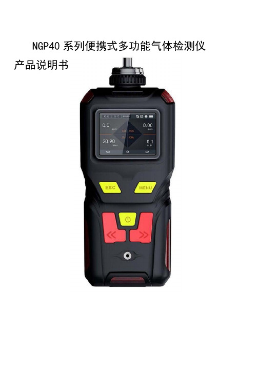
NGP40系列便携式多功能气体检测仪产品说明书产品说明书一、NGP40便携式多功能气体检测仪概述NGP40系列便携式多功能气体检测仪用于:快速检测多种气体浓度及环境温湿度测量,测量超过限值则发出声光振动报警。
NGP40采用2.31寸高清彩屏实时显示,采用行业知名品牌的气体传感器,主要检测原理有:电化学、红外、催化燃烧、热导、PID光离子等。
先进的电路设计、成熟的内核算法处理,独特的外形设计,取得了多项软件著作和外观等专利。
NGP40适用于检测管道中或受限空间、大气环境中的气体浓度;气体泄漏或各种背景气体为氮气或氧气的高浓度单一气体纯度。
检测气体种类超过500余种。
二、NGP40便携式多功能气体检测仪产品特点:★可以同时检测1~4种气体,单位自由切换单位可选:PPM、mg/m3、V ol%、LEL%、PPHM、ppb、mg/L。
★内置泵吸式测量,集成水汽、粉尘过滤器,防止因水汽和粉尘损坏传感器和仪器,可用于高湿度、高粉尘环境响应迅速;特殊气路设计,采样距离大于10米,可直接检测负压或正压-0.5~2公斤的气体★丰富的人机界面2.31寸高清彩屏,显示实时浓度、报警、时间、温度、湿度、存储等信息;菜单界面采用高清仿真图形显示各个菜单的功能名称。
★大容量数据存储功能(容量可定制),支持多种存储方式,选配RS485通讯标配10万条数据存储容量;支持实时存储、定时存储,或只存报警浓度数据;支持本机查看、删除数据,和通过USB接口上传到电脑进行数据分析或打印。
★高温气体检测(选配)选配高温采样降温过滤手柄或高温高湿预处理系统可检测400度温度的烟气。
更高温度的气体检测可订制。
★三种显示模式可切换同时显示四种气体浓度,大字体循环显示单通道气体的浓度,实时曲线显示。
★图形化显示,以曲线形式反映一段时间内气体浓度变化走势●数据恢复功能,如遇误操作可以选择部分或全部恢复●可设置是否显示最大值、最小值、平均值●标准USB充电接口,具有充电保护功能,支持USB热插拔,充电状态仪器可正常工作●采用4500mA大容量可充电高分子聚合物电池,可长时间连续工作●高精度温湿度测量(选配)●支持实时检测或定时检测,不检测时可以把泵关闭以延长开机时间●多种报警方式,报警时多方位立体指示报警状态包含声光报警、振动报警、显示屏视觉报警。
APEG-D系列说明书0207臭氧仪
感谢您选择安帕尔“大众”系列固定式气体检测仪!为确保人身和系统安全,并使产品达到最佳性能,在产品安装、使用和维修前,请完全阅读和理解本手册中的内容,特别是警告和注意的事项。
警告固定式气体检测仪安装必须符合相关的国家标准。
▶为保证固定式气体检测仪整体的合格性,对固定式气体检测仪的任何操作,必须由受过专门培训的人员来执行;并且要确保遵循了当地的规章制度和现场的操作程序。
▶禁止在潜在危险环境下打开固定式气体检测仪机壳、替换或改装传感器;在固定式气体检测仪运行期间要保持装配紧密连接,打开固定式气体检测仪机壳前,必须断开固定式气体检测仪所有电气线路的连接。
▶为了保证漏电流安全和避免电磁波干扰,固定式气体检测仪必须可靠接地。
应确保同一气体监测系统下的所有固定式气体检测仪和气体报警控制主机的接地端相连并与大地可靠连接,不要各自连接到大地。
▶固定式气体检测仪的内部和外部各有一个接地点,内部接地点应优先作为设备接地,外部接地点只是补充的绑定连接;只有当地权威机构要求时,才可采用外部接地点。
提示▶固定式气体检测仪的安装位置请尽量远离大功率的设备,如电机,射频设备。
▶固定式气体检测仪的电源不要与大功率设备共用,因大功率设备的电源可能对固定式气体检测仪的正常工作造成影响。
▶固定式气体检测仪的电源线不要与高压线(如220VAC)布置在同一线槽,如现场无法避免,则必须分别选择屏蔽铠装线材,但仍有引起固定式气体检测仪工作异常的可能。
▶若安装在户外,则应注意外界因素的影响,如淋雨或浸水。
▶通常应记录固定式气体检测仪的安装位置,以及电缆的布线情况,以便于维护。
深圳市安帕尔科技有限公司真诚接受任何针对本说明书内容上的错误或遗漏而提出的批评指正。
目录1、产品简介及应用领域- ------------------------------------------- 42、产品特点--------------------------------------------------43、产品分类及型号定义-----------------------------------------------54、技术参数---------------------------------------------------- 65、产品结构------------------------------------------------8 5.1、总体结构介绍----------------------------------------- 8 5.2、主要部件结构--------------------------------------- 95.3、产品尺寸图--------------------------------------96、产品现场安装固定、现场布线、内部接线操作说明-------------------10 6.1、安装环境--------------------------------------------------10 6.2、安装位置---------------------------------------------10 6.3、固定式气体检测仪的安装方法--------------------------------11 6.4、不同信号输出仪表的信号传输距离及电缆选择------------------ 12 6.4.1、有线“大众”系列固定式气体检测仪--------------------- 12 6.4.2、其它说明----------------------------------------------- 13 6.5、“大众”系列无线固定式气体检测仪---------------------------14 6.6、固定式气体检测仪端子接线指导-------------------------------156.6.1、接线方法------------------------------------------------157、操作方式说明--------------------------------------------------16 7.1、遥控器使用操作说明-----------------------------------------167.2、仪表按键使用操作说明---------------------------------------178、检测仪使用操作说明--------------------------------------------- 17 8.1、开启设备----------------------------------------------------17 8.2、菜单功能介绍及使用说明--------------------------------------188.2.1、进入配置列表方法--------------------------------------- 188.2.2、配置列表操作详细说明----------------------------------- 19气体标定---------------------------------------------------- 19报警设置--------------------------------------------------23 通讯设置-------------------------------------------------24 恢复出厂------------------------------------------------24 时间设置-------------------------------------------------24 输出调节----------------------------------------25 密码设置---------------------------------------------25 其他设置----------------------------------------------258.3、工作状态说明---------------------------------------------- 269、检测仪标定操作说明----------------------------------------------289.1、气体标定的定义---------------------------------------------289.2、标定前注意事项------------------------------------ --------289.3、什么情况下需要标定-------------------------------- --------289.4、标定前的准备-----------------------------------------------289.5 、气体检测仪的零点标定--------------------------------------299.6、仪表的高点(或称目标点)标定流程-----------------------------30 9.6.1、单个高点标定流程---------------------------------------309.6.2、多级高点(或称目标点)标定流程---------------------------319.7标定结果测试------------------------------------------------3310、传感器更换及保养--------------------------------------- 3311、故障现象和排除-----------------------------------3412、责任限定------------------------------------------- 3413、附表----------------------------------------------------351、产品简介及应用领域“大众”系列固定式气体检测仪是安帕尔公司根据客户市场需求和多年行业应用经验推出的一款低价格、高性能、功能齐全的现场在线监测固定式气体检测仪。
泵吸式三氟化氯气体报警分析仪(网络版)
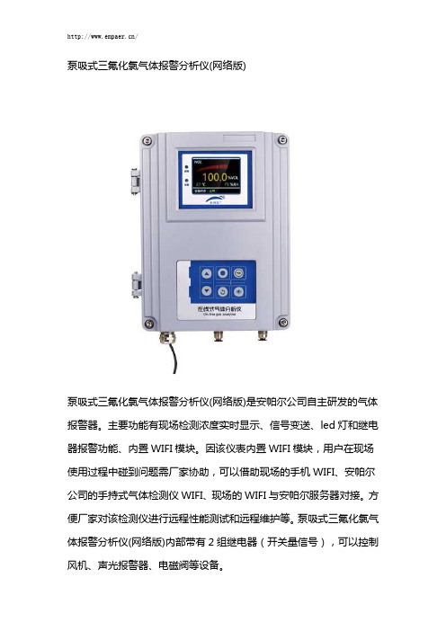
泵吸式三氟化氯气体报警分析仪(网络版)泵吸式三氟化氯气体报警分析仪(网络版)是安帕尔公司自主研发的气体报警器。
主要功能有现场检测浓度实时显示、信号变送、led灯和继电器报警功能、内置WIFI模块。
因该仪表内置WIFI模块,用户在现场使用过程中碰到问题需厂家协助,可以借助现场的手机WIFI、安帕尔公司的手持式气体检测仪WIFI、现场的WIFI与安帕尔服务器对接。
方便厂家对该检测仪进行远程性能测试和远程维护等。
泵吸式三氟化氯气体报警分析仪(网络版)内部带有2组继电器(开关量信号),可以控制风机、声光报警器、电磁阀等设备。
检测速度快内置进口气泵报警方式多样提醒和报警功能齐全黑匣子功能搭载第三代‘COVE三氟化氯’系列传感器模组工业级的EMC模组内置WIFI模块物联网功能超高清彩色显示屏双语操作系统隔爆设计操作指引零点自动校正泵吸式三氟化氯气体报警分析仪(网络版)简介泵吸式三氟化氯气体报警分析仪(网络版)是安帕尔公司自主研发的气体报警器。
主要功能有现场检测浓度实时显示、信号变送、led灯和继电器报警功能、内置WIFI模块。
因该仪表内置WIFI模块,用户在现场使用过程中碰到问题需厂家协助,可以借助现场的手机WIFI、安帕尔公司的手持式气体检测仪WIFI、现场的WIFI与安帕尔服务器对接。
方便厂家对该检测仪进行远程性能测试和远程维护等。
泵吸式三氟化氯气体报警分析仪(网络版)内部带有2组继电器(开关量信号),可以控制风机、声光报警器、电磁阀等设备。
泵吸式三氟化氯气体报警分析仪(网络版)特点★检测速度快:“泵吸在线”系列三氟化氯检测仪对比同行同类产品,检测速度快;★内置进口气泵:保证了气室内气流的稳定性和气压的稳定性,提高仪器检测的精度★报警方式多样:仪表显示屏led灯、声光报警等和继电器报警★提醒和报警功能齐全:传感器到期提醒功能、超浓度报警功能、超温湿度报警功能、故障报警功能、仪表标定提醒功能等;★黑匣子功能:操作、报警记录,超温度使用记录,超湿度使用记录,超量程使用记录;★搭载第三代‘COVE三氟化氯’系列传感器模组,部分具有温湿度监测与补偿功能;★工业级的EMC模组,应对严酷的现场环境干扰;★内置WIFI模块:可以在有WIFI信号覆盖的区域,实现信号无线传输;★物联网功能:可连接安帕尔服务器来实现手机和电脑远程数据监控、报警提醒、报警值设置、远程售后服务等;★超高清彩色显示屏。
PV3900-2000_汽车内部的部件_气味检验最新版
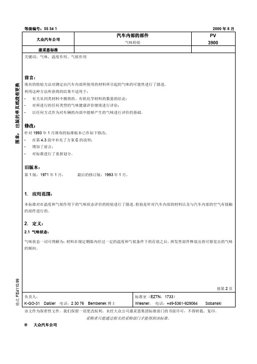
负责人 K-GO-31 Daßler 电话 2 30 76 Bembenek 博士
标准室 EZTN,1733 Wiesner, 电话 +49-5361-929064
接第 2 Sobanski
该文 为保密性文 我们保留一 更改权利 未 大众公 康采恩集团标准部门的书面许可, 得转载 复印
© 大众汽车公
5. 用的资料
DIN 50 011-12
气候及其技术应用 空调设备 空调数值 空气温度
产的“Einkochspaß”型容器选择用于对检验进行手工实施的 1I-容器 为进行重复测 ,推荐使用 3I-容器 检验容器应 在 次检验过程之前进行清洗 例如 使用实验漂洗机 并必须是 净及无异味的—推荐 纽锐 科技 Newaystek
4.2 试样预处理
试样预处理只能够对符合规定的特殊材料进行 另外,检验可按发 状态进行
1. 应用范围
本标准对在温度和气候作用下的气味状态评 的检验进行了 述 检验是针对汽车内部的材料以及 汽车内部的空气 接触 的部 进行的
2. 定
2.1 气味状态 气味状态一词可理解为 材料在规定期限内 过一定的温度和气候条 下的存放之 ,挥发性部 释放出的可察觉出的气味 的倾向
格式 FE4110.99
5534大众汽车公大众汽车公大众汽车公大众汽车公汽车内部的部汽车内部的部汽车内部的部汽车内部的部气味检验pv3900康采恩标准康采恩标准康采恩标准康采恩标准关键词气味温度作用气候作用前言前言前言前言现的检验方法对测定由汽车内部所使用的材料所引起的气味的可能性进行了述利用这种方法所获得的结果用于以任何方式作为对车辆的内部中能够产生的气味进行评的基础修改修改修改修改在第43段中补充了方案c的说明对标准进行了重新划旧版本旧版本旧版本旧版本应用范围应用范围应用范围应用范围本标准对在温度和气候作用下的气味状态评的检验进行了述检验是针对汽车内部的材料以及汽车内部的空气接触的部进行的21气味状态气味状态气味状态气味状态气味状态一词可理解为材料在规定期限内过一定的温度和气候条下的存放之挥发性部释放出的可察觉出的气味的倾向负责人kgo31daler电话23076bembenek博士标准室eztn1733wiesner电话495361929064sobanski该文为保密性文我们保留一更改权利未大众公康采恩集团标准部门的书面许可得转载复印采购者只能通过相关的采购部门才能得到该标准大众汽车公大众汽车公大众汽车公大众汽车公第二pv3900200008标记标记标记标记31检验结果标记举例检验结果标记举例检验结果标记举例检验结果标记举例气味检验pv3900note3032tl图纸等中的理论值规定的标记举例图纸等中的理论值规定的标记举例图纸等中的理论值规定的标记举例图纸等中的理论值规定的标记举例气味检验pv3900note2533标记的结构标记的结构标记的结构标记的结构参看图1气味检验pv3900检验规程检验体存放条检验检验检验检验41检验仪器检验仪器检验仪器检验仪器带制通风的加热室符合din5001112标准精度等2可使用带气味中性密封和盖子的1i玻璃容器作为检验器皿例如可使用在日用品商店可买到的leitheit产的einkochspa型容器选择用于对检验进行手工实施的1i容器为进行重复测推荐使用3i容器检验容器应在次检验过程之前进行清洗例如使用实验漂洗机并必须是净及无异味的推荐纽锐科技newaystek42试样预处理试样预处理试样预处理试样预处理试样预处理只能够对符合规定的特殊材料进行另外检验可按发状态进行43试样体试样体试样体试样体个层次参看表格1abc的排列是根据在车辆内部使用的材料的数份额来确定的第三pv3900200008表格表格
QPN-I介绍

目录
1 原因动机 2 什么是成熟度和QPNI? 3 方法和系统 4 QPN-I是Tevon中的系统 5 运行状态
Seite 2
一名飞行员的一天
“… 在给飞机加满油之后,飞行员 首先开始对飞机进行外观检查。 在 飞机起飞之前进行的这个巡视检查, 是为了检验飞机上的可见故障。
尤其需要注意的是承重表面, 以及其附属的翻转系统, 驱动装置, 底盘和刹车。飞行员以经过培训的 专业人士眼光来检查飞机可能发生 的故障 …”
Seite 15
Volkswagen AG采购条件
IX. 质量和文献记录
1.供应商的供货的产品都有技术含量,其技术内容要符合安全标准和约 定好的技术信息。 只有得到订货方书面同意之后,才能对供货状态进行 更改。
1998年在美因河畔法兰克福,VDA-文件“供货质量安全-供应商 选择/生产过程-和产品认可/批量质量绩效”,对样件认可给出说 明。只有当订货方接受样件之后,才可以开始批量供货。
和产品技术部门 进行对接, 例如
GQE
… TOP-Q, 外购件领导 大会, KAF-
Umfeld
Seite 25
辅助供应 – 举例: 虚拟试模 (VTO)
VTO实现了早在物理实物产品诞生之前,早期阶段的新车型总零件(外购件和自制件)挑选。
质保通过VTO得到支持:
● 在成熟度保障过程中(RGA) ● 在新零件提升项目中(QPN) ● 针对车辆使用安全内容 ● 在KV比例制定过程中
Seite 16
VDA 成熟度 vs. VDA 2?
≠
例如,
- 制定样件认可规划 - 整合框架条件:
质量框架约定, 指定零件, … - 参看VDA成熟度保障,
并且和其相关
大众标准 PV3938
3对检测空间的要求检测空间要足够摆放两辆汽车。
其中一辆汽车在被检测的时候可以对另外一辆作检测准备。
除此以外空间还要足够大以方便散去红外线仪器工作时排放的热量。
务必杜绝火灾的危险。
检测空间内必须不带任何特殊气味。
机动车装配车间或者涂料工作室以及类似的地方不能用作此检测之用。
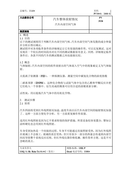
4红外线仪器以及对其要求四部红外线仪器,功率各为3.3千瓦。
照射板大小为100厘米x80厘米。
仪器由热电偶控制。
通过设定最大限度的物体温度能保护汽车。
四部红外线仪器将放在汽车的四面。
仪器距离车身50厘米。
照射面应该与汽车玻璃面平行。
此项要求请参照以下图示。
图一:仪器与车身应按图示摆放。
4.1监测温度通过预先设定红外线仪器达到的最大温度这项指标能有效地保护汽车。
照射板照到车身上最热的位置安装探测器。
推荐加热温暖最高限度为110°C。
车身温度要纪录备案。
5对车身的要求为了让测试有重复操作性,让测试结果有对比性,汽车的温度和时间都应详细纪录。
这里的时间指的是被检测汽车的已使用时间应该大致一样。
举例来说,如果在汽车装配完毕后马上测试有良好的可比性。
只要是同一套装配程序,同一型号的车在流水线上的装配时间相差无几。
5.1前期准备从经验总结,刚装配好的汽车含有浓烈的溶媒浓缩剂。
这现象很不利于一项详细的辐射测试。
因此汽车在受检测之前需要严格地遵照规定做前期处理。
汽车所有窗户打开,在室温中置放24小时。
较易挥发溶媒的浓度会通过这样的处理显著地降低。
5.2加温曲线加温中汽车车身的温度会在特定位置量取。
这个位置是前排座位头部靠垫的正中间以及距离车顶20厘米(下文继续解释)。
汽车车身最初加热升温的幅度需要比较大。
三小时内测试位置量取的温度应该达到65°C(上下5°C)。
到第四个小时结束时温度都要保持如此。
四小时以后开始测试。
整个测试过程中该位置的温度都要纪录备案。
同样,测试过程中火焰离子侦测器的值也要纪录。
一旦温度曲线呈平行延展的趋势,理想状态中,火焰离子侦测器之值也应该饱和。
- 1、下载文档前请自行甄别文档内容的完整性,平台不提供额外的编辑、内容补充、找答案等附加服务。
- 2、"仅部分预览"的文档,不可在线预览部分如存在完整性等问题,可反馈申请退款(可完整预览的文档不适用该条件!)。
- 3、如文档侵犯您的权益,请联系客服反馈,我们会尽快为您处理(人工客服工作时间:9:00-18:30)。
“大众”系列固定式三氟化氮检测仪(网络版)
一、“大众”系列固定式三氟化氮检测仪(网络版)简介
“大众”系列固定式三氟化氮检测仪(网络版)有多个别称,可以叫做“大众”系列在线式三氟化氮检测仪(网络版)、“大众”系列壁挂式三氟化氮检测仪(网络版)等等。
“大众”系列固定式三氟化氮检测仪(网络版)可以同时具有现场检测浓度显示、信号变送、led灯和继电器报警功能。
“大众”系列固定式三氟化氮检测仪(网络版)工作原理是将现场检测到的三氟化氮气体浓度,转换为对应的标准信号(如电压信号(如0-5/10V)、电流信号(如
4-20mA)、标准数字信号(如总线三氟化氮S-485、三氟化氮S232)、频率信号、Hart协议信号,然后将信号变送到PLC、DCS、报警控制主机等上位机进行统一显示、管理和控制。
“大众”系列固定式三氟化氮检测仪(网络版)内部带有1个继电器(开关量信号),可以控制风机、声光检测仪、电磁阀等设备。
二、产品分类
三、“大众”系列固定式三氟化氮检测仪(网络版)特点
★快速反应。
“大众”系列固定式三氟化氮检测仪(网络版)对比同行同类产品,检测速度快;
★多级标定功能。
可实现高精度检测的成熟技术,已经过市场多年验证;
★零点自动校正。
针对某些环境应用,仪表可实现零点自动校正功能;
★标准信号输出种类齐全。
“大众”系列固定式三氟化氮检测仪(网络版)有线输出信号有多种选择。
★提醒和报警功能齐全传感器到期提醒功能、超浓度报警功能、超温度报警功能、故障报警功能、仪表标定提醒功能等;
★物联网功能。
“大众”系列固定式三氟化氮检测仪(网络版)可连接服务器来实现手机和电脑远程监控、报警提醒和报警值设置等;
★超高清彩色显示屏。
“大众”系列固定式三氟化氮检测仪(网络版),远距离可视,可视距离10米(5.0视力);
★操作指引。
人性化设计,每个功能设置都有操作指引,防止客户误操作,行业独一无二;★双操作方式。
按键操作+遥控操作;
★双语操作系统。
可以实现中英文系统切换,默认中文操作系统;
★隔爆设计、本安设计、三氟化氮oHS设计;
★黑匣子功能。
操作、报警记录,超温度使用记录,超量程使用记录;
应用领域
“大众”系列固定式三氟化氮检测仪(网络版)广泛应用于石油化工、工业生产、冶炼锻造、电力、煤矿、隧道工程、环境监测、污水治理、生物制药、家居环保、畜牧养殖、温室培植、仓储物流、酿造发酵、农业生产、消防、燃气、楼宇建造、市政企业、学校实验室、科研中心等行业。
五、系统图
六、产品尺寸与安装示意图
七、产品尺寸与安装示意图
/。