散热片之E320L小型加工中心
西门子SINAMICS S120流动冷却机械说明书

FOR HARSH ENVIRONMENTAL CONDITIONS SINAMICS S120liquid-cooledSINAMICS S120 liquid-cooledTHE DRIVE FAMILY FOR FUTURE-PROOF DRIVE SOLUTIONSSINAMICS – the optimum drive for every applicationSINAMICS offers you the optimum drive for every application. All of the members of this converter family can be engineered, parameter-ized, commissioned and operated in the same standard way. One drive system – to tackle every application.Low voltageStandard performance convertersIndustry specific convertersHigh performance convertersV20G120C G120G130 / G150G120X G180S120S1500.12 – 30 kW0.55 – 132 kW0.55 – 250 kW75 – 2.700 kW0.75 – 630 kW2.2 – 6.600 kW0.55 – 6.840 kW75 – 1.200 kWSINAMICS S120 liquid-cooledSINAMICS S120 liquid-cooledis part of the SINAMICS family• Wide range of power ratings from 0.12 kW to 85 MW • Available in low-voltage, medium-voltage and also DC versions• High degree of flexibility and combinability• Simple link to SIMATIC control systems, seamless integration in the automation landscape as well as part of Totally Integrated Automation• Higher-level, standard Safety Integrated concept • Standard engineering for all drives–SIZER for engineering–STARTER / SINAMICS Startdrive for parameterizing and commissioning Medium voltageGrid converter Servo converters Distributedconverters For demanding applications with high power ratingDCM (DC)PCS SIMATICMICRO-DRIVE V90S210S120M G115D / G120D GL150 / SL150SM120 CM /SM150 / GM150GH150 / GH1806 kW – 30 MW435 – 870 kW0.1 – 1 kW0.05 –7 kW0.05 – 7 kW0.25 – 1.1 kW0.37 – 7.5 kW 2.8 – 85 MW0.8 – 58 MW0.15 – 28.5 MWSINAMICS S120liquid-cooledThe clever alternative for harsh environmental conditionsLiquid-cooled SINAMICS S120 convert-ers are predestined for harsh condi-tions. High degrees of protection can be achieved when using these devices. They are also not affected by dirty or aggressive ambient air. When compared to air-cooled versions, liquid-cooled ver-sions have a footprint that is up to 50 % smaller than for chassis devices – an ideal solution where mounting space is restricted. Less space is required in the control cabinet as a result of the lower envelope dimensions. Not only this, these liquid-cooled drive systems are especially quiet, efficient and require little maintenance. In many applica-tions, the heat recovery can create additional energy saving potential. In this case, the cooling water that has been heated up can be used for process heat, heating or process water.Independent of the ambient airAs the power loss for liquid-cooled SINAMICS S120 can be very effectively dissipated to the cooling liquid, sealed control cabinets in an IP55 degree of protection can be easily implemented. The ingress of dusty or aggressive air is just as low as the humidity, spray water or salt-laden sea air in marine applica-tions. Even high ambient temperatures are less critical when compared with air-cooled devices as the thermal load is essentially determined by the cooling water temperature. Further, the tem-perature in electrical rooms does not increase as much.SINAMICS S120 liquid-cooled – advantages at a glance • Highest power density throughefficient cooling• Predestined for applications where space is restricted• High degrees of protection can be simply implemented • Perfectly suitable for dusty and aggressive ambient air and low-noise operation • Redundant cooling systems can be implemented with low additional costs• Reduction of expenses for room air conditioning• Maintenance and operating costs can be reduced• Additional energy saving potential by recovering heatEFFICIENT AND RUGGEDLiquid-cooledSINAMICS S120SINAMICS S120 liquid-cooledUp to 50 % smaller footprintWhere space costs a lot of money – for instance on ships, offshore platforms and industrial plants and systems – liquid-cooled converters are attractive as a result of their extremely compact design. These reduce the footprint by about 50 % when compared to air-cooled chassis devices with the same power rating, as they require signifi-cantly smaller envelope dimensions as a result of the more effective cooling. The control cabinets can be designed smaller as the chassis units require less space. In turn, this means that electrical rooms can be made smaller, which also has a positive impact on the civil engi- neering costs.Quiet and low maintenance Liquid-cooled versions certainly make sense where cooling water is available anyway. This is because significantly less climate control is required for the electrical rooms that accommodate the converters. SINAMICS S120 convertersare quieter to start off with as they have no fans. No additional noise dampening measures are required for typically up to 60 db (A). This is the reason that these converters are recommended for applications that are sensitive to noise, for example on cruise ships – and when directly located close to workplaces in production envi- ronments. And, last but not least, eliminating fans enhances drive relia- bility – and, in turn, plant availability.Climate control is not required For liquid cooling, up to 95 % of the power loss is dissipated through the cooling medium. This means that the temperature of the ambient air sur-rounding the converter hardly increases, and complex climate control can be eliminated – this is an important issue for retrofit and modernization projects. A redundant cooling system can be easily configured using two pumps in the cooling system, and can be imple-mented with low associated costs.Cost-saving, compactand versatileAdditional energy savingpotential by recovering heatIn addition to the energy savings as a result of the efficient cooling concept, heat can also be recovered. The cooling water that is heated up as part of the cooling process can be used for process heat, heating or hot water at no charge. Using a heat pump, the cooling water temperatures can be increased in an energy-efficient fashion. An espe-cially high amount of energy can be saved if hot water is required for the production process, which for example, is the case when manufacturing paper. Cost savings can also be realized for heating and for hot water required in production and office environments. As a consequence, these devices fre-quently have a payback time of just several years.Energy savingsContrary to converters with a rectifier input on the line side, SINAMICS S120 converters equipped with an Active In-feed can feed back energy into the line supply. This means that they can save a lot of energy. Further, for multi-axis sys-tems, it is also possible to transfer the energy (energy balancing). For example, for crane applications when the load is lowered, energy is recovered that can then be used to power the crane trolley. By connecting up to four identical liquid-cooled modules in parallel, power rat-ings of up to 5,700 kW can be realized on the motor side and up to 6,460 kW on the line side. Sophisticated cooling systemThe compact design and high efficiency of liquid-cooled SINAMICS S120 devices is based on a sophisticated cooling sys-tem. All of the main components, such as power semiconductors, DC link capac-itors and symmetrizing resistors, can be cooled by the cooling circuit. Only a low amount of cooling liquid is required as a result of the physical attributes of water. As a consequence, the required flow rate is very low. This factor reduces the drive power of the pumps when com-pared to fan power ratings. As a conse- quence, power costs are very low, whichnoticeably reduces the operating costs,especially for those plants and systemsthat operate continuously.The standard modular systemFor liquid-cooled SINAMICS S120, acomplete range of standard as well astype-tested components are available.These can be flexibly combined to createthe optimum solution for customizedapplications. Supplementary compo-nents such as heat exchanger modulesand piping can be simply integrated.Liquid-cooled SINAMICS S120 devicescan also be mounted horizontally.The ideal industry solutionIn a wide range of industries, the liquid-cooled concept provides considerableadvantages. For example, in the process,paper and steel industries, where a con-trol cabinet solution with a high degreeof protection against dirt and watermakes sense. The same applies to plantswith high dust loads such as cementfactories, mining companies or tunnelboring machines. In the automotiveindustry (e.g. on test benches) or inapplications in the food industry, wherethe control cabinets in the productionhall are cleaned with water for hygienicreasons. For applications in less harshenvironments, reduced space require-ments, lower costs for room air condi-tioning and heat recovery for hot processand service water pay off.Champion in shipbuilding andoffshore applicationsSince every square meter counts here,the space-saving design in marine appli-cations pays off especially well. Thesame applies to the fact that the heatgenerated during the cooling process isremoved from the already warm switch-gear rooms and transferred to the sea-water via heat exchangers. In addition,the saline atmosphere cannot penetrateinto the device electronics due to thetightly closed control cabinet. Based onthe comprehensive SINAMICS modularsystem, highly compact solutions formain and auxiliary drives as well as theintegration of energy storage systemscan be realized. The liquid-cooledSINAMICS S120 converters thus play akey role in electrification and decar-bonization in the shipbuilding industry.It goes without saying that all systemcomponents are marine certified(DNV and ABS).SINAMICS S120liquid-cooledModularity for customized solutions SINAMICS S120 Cabinet Modules comprise converter modular cabinet modules that can be combined to address the particular drive application. As a consequence, almost any drive solution can be optimally implemented. This modular system is especially suit- able for multimotor drive configura-tions with central line infeed and a common DC link busbar.Simple planning, straightforward serviceThe liquid-cooled SINAMICS G120 Cabinet Modules represent a com- pletely new development that sets itself apart in every phase of the product lifecycle with a high degree of cost effectiveness and simplicity – from planning and procurement throughmounting/installation and commission-ing up to everyday operation and service. Further, these systems offer an excellent price-performance ratio, and can be integrated into any automation solution.Rugged and straightforward for the highest degree of reliability With their rugged, straightforward design, the SINAMICS S120 Cabinet Modules system is extremely reliable. A special cabinet design guarantees a high degree of mechanical endurance. Another additional positive issue: nickel-plated standard busbars and coated electronic modules are pro- tected against the effects of the envi-ronment. It goes without saying that all of the components – from the produc-tion of individual parts up to a ready-toSINAMICS S120 Cabinet Modules:liquid-cooled cabinet systems – can be flexibly combined in a modular wayThe highlights at a glance• High degrees of protection up to IP55 can be easily implemented • Cabinet system used: Rittal TS8, 2,200 mm high (industrial standard)• Can be engineered using known engineering tools, simply ordered based on an article number and with short delivery times• A comprehensive range of options supports flexible adaptation to address specific requirements as for the marine industry• Series device with type-tested design, for example the appropriate partitions for optimally cooling the passive components and corrosion-resistant, favorably priced plastic pipes• Comprehensive documentation is available in many languages• Spare parts can be called up via SparesOnWeb as the components used have been standardized• Marine certified cabinet design as well as individual acceptance tests by various certification centers available as an optionconnect cabinet – are subject to exten-sive checks throughout the complete production process. This guarantees a high degree of functional reliability when configuring, commissioning and in operation.Operational reliability built inAll SINAMICS S120 Cabinet Modules have been developed according to the zone concept, which means that they offer the highest degree of operational reliability. EMC design measures have been consequentially implemented. Partitions to guide the air and control temperature gradients have been de-signed based on simulation runs.SINAMICS S120 liquid-cooledSINAMICS S120 liquid-cooled – voltage ranges and power ratings1)R ated power of a typical 6-polestandard induction motor at 3AC 400 V / 50 Hz or 3AC 690 V / 50 Hz 2) T he current derating required as a result of the parallel connection has already been taken into account 3)O ptimized regarding space and weight SINAMICS S120 liquid-cooledSkalierung auf Skalierung auf Skalierung aufSkalierung aufThe drive, that optimizesyour energy efficiencySINAMICS S120 liquid-cooledElectric drives use about two thirds of all industrial electric power.This is why it is decisive to use drive technology right from thestart to already effectively reduce future energy consumption inthe engineering phase – thus optimizing plant/system availabilityand process reliability.11Follow us on:/siemensindustry /siemensPublished bySiemens AGDigital IndustriesMotion ControlP.O. Box 31 8091050 Erlangen, GermanyFor the U.S. published by Siemens Industry Inc.100 Technology Drive Alpharetta, GA 30005United StatesSubject to change without prior notice Article No.: DIMC-B10077-00-7600 Dispo 21500Printed in GermanyWÜ/1000173743 WS 1021 PDF© Siemens AG 2021The information provided in this brochure contains merely general descriptions or character-istics of performance which in case of actual use do not always apply as described or which may change as a result of further development of the products.The required performance features are only binding if they have been expressly agreed upon in the form of a written contract. All product designations may be trademarks or product names of Siemens AG or supplier companies whose use by third parties for their own purposes could violate the rights of the owners.To ensure the secure operation of Siemens products and solutions, it is necessary to take suitable preventive measures (e.g. cell protection concept) and integrate each component into a state-of-the-art holistic industrial security concept. When so doing, products from other manufacturers should be taken into account. For more information about industrial security, visit /industrialsecurityDigitalization solutions for low-voltage convertersWhether virtualization and simulation, dimensioning and configuring, connectivity, data analysis or services – digitalization opens up greater efficiency and reliability in planning, operation and maintenance.Get the most out of the converter data through digitalization. From digital converter twins, selection and engineering tools, and connectivity solutions to analytics apps and data-based services – the digitalization portfolio for drive technology enables optimized development processes, demand-oriented maintenance planning, and ensures higher productivity. https:///digital-drives。
NC-320主要技术参数
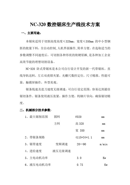
NC-320数控锯床生产线技术方案一、主要用途:本锯床适用于切割高度高度≤320mm,宽度≤350mm的中小型钢胚的批量下料,全自动控制,人机界面操作,简单方便。
在选取适当的参数调整不同速度后,可切割各种形状的软硬铝棒,是各种加工企业高效节能的理想切割设备。
NC-320卧式带锯床是本公司自行设计开发的新一代带锯床。
直线导轨送料,左右双虎钳夹紧,光栅尺数控定位,尺寸精准,性能可靠,触摸屏操作,外型美观。
锯条线速及进刀速度无级调速,可自行设定范围,容易达到最佳锯切条件。
锯条使用液压张紧,操作方便,钨钢片导向,确保锯切精度。
二、机械部分技术参数:1、最大锯削范围圆料Ø320 mm方料高320 mm宽 350 mm2、带锯条规格 4115*34*1.1 mm3、锯带速度变频调速 20--90 m/min4、进给速度液压无级调速5、主电动机功率 3.0 Kw6、液压电动机功率 0.75 Kw7、冷却电动机功率 90 W8、液压油箱容量 60 L9、液压系统压力 3.0 Mpa10.单次自动送料长度 400 mm*送料长度超过400mm可自动循环累加达到预定尺寸11.自动送料循环精度≤ 0.2 /次 mm12.上下锯切垂直精度 < 0.1/100 mm13.储料系统容量并排10根Ø 230mm原料长6米14.自动拨料材料范围Ø200- Ø 230 mm(注;锯切之原材料直线度偏差≤ 2mm/m)15. 动力式钢刷16. 动力式铁屑排除器17.光栅尺送料定位18.断带,卡带,自动停机19.成品料自动存储20.带铖条锯缝仅为1.8mm, 而普通圆盘锯片锯缝为18mm, 大大节省材料,从而降低成本.21.速度快,效率高,直径200-230mm的铝棒,最快速度为:15-20件/小时.三、电器技术参数:1.主要电器品牌配置参数a: 触摸屏西门子 5.6“触摸屏b: PLC 西门子c: 电器控制元件正泰d: 光栅尺万濠e: 电磁阀北部精机2.电器安全配置参数a:故障程序保护禁止运行b: 触摸屏故障监控显示c: 机床三色报警灯(运行为闪绿,故障直黄,维修直红)d: 安全盖打开停机报警e: 锯带断带卡带停机报警f: 电器回路中短路、过载等保护元件g: 油温散热保护3.可编程控制模式a: 手动模式此模式下全部手动工作,点击触摸屏进入手动控制页面,确认手动启动,所有动作只可以手动点击b: 自动模式有料状态下,输入锯切数量,锯切长度等参数后,点击触摸屏进入自动控制页面,机械归零,自动启动,系统自动完成设定任务c: 拨料送料模式无料状态下,系统自动感测确认无料后,锯切停止,,系统自动拨料,进入拨料送料程序拨料送料程序动作顺序当一种规格材料锯切完成后,送料钳口夹紧时无料感测,程序进入送料状态,此时锯切,送料虎钳全部松开(松开距离大于锯切时虎钳松开距离,以防止原材料弯曲造成的碰撞干涉),拨料---进入平台输送架---后虎钳夹紧---轨道送料----顶出上次锯切残料---触动前限位开关---后虎钳松开退回原位---送料,锯切虎钳夹紧材料---锯料头---开始正常循环锯切状态拨料送料机构说明机构组成:1.存料,拨料系统及料架,采用杠杆原理拨料,2.平台输送架(滚筒台面),当材料经拨料系统后导入此料架两侧挡止固定3.独立虎钳夹持轨道送料系统,当材料进入平台输送架,独立虎钳立即夹紧材料,虎钳下方配备轨道和滚轮组,直线油缸驱动,把原材料送入工作区域,顶出残料料架配置1.7米存料架,2.7米滚筒料架(后部)3.6米滚筒料架(前部)4.1.5米成品存料架5.独立虎钳送料机构,送料入工作区域,顶残料6.立滚筒,挡立板,防侧翻装置7.拨料臂4支,拨料油缸4支8.推料油缸1只,四、其他机构说明及性能配置●高强度皮带轮经过精密平衡校正,运转平稳,震动小●锯条速度根据材料特性合理设置,操作简单,使用可靠,提高切削效率,更有利于延长锯条寿命。
Powertec i250C i320C电气方案备用零件说明说明书

Spare Parts - Electrical Schematic Spare Parts - Electrical Schematic1 IM3070 09/2018 REV03POWERTEC i250C STANDARD POWERTEC i250C ADVANCED POWERTEC i320C STANDARDPOWERTEC i320C ADVANCEDSpare Parts (2)Figure A: Powertec i250C/i320C STD/ADV Machine Assembly .................................................................................. 2 Figure B: Powertec i250C/i320C STD/ADV Inside Machine Assembly ....................................................................... 4 Figure C: Powertec i250C/i320C STD/ADV Wire Drive Assembly ............................................................................... 5 Figure D: Powertec i250C/i320C STD Front Assembly ................................................................................................ 6 Figure E: Powertec i250C/i320C ADV Front Assembly (6)Electrical Schematic (8)Lincoln Electric Bester Sp. z o.o.ul. Jana III Sobieskiego 19A, 58-263 Bielawa, Polandwww.lincolnelectric.euSpare Parts - Electrical Schematic Spare Parts - Electrical Schematic2 Spare PartsSP50430, SP50431, SP50432, SP50433 REV03ASSEMBLY PAGE NAMEP o w e r t e c M a c h i n e A s s e m b l yM a c h i n e F r o n t A s s e m b l y W i r e D r i v e A s s e m b l y & E u r o S o c k e t A s s e m b l yP o w e r t e c i 250C /i 320C S T D F r o n t A s s e m b l y P o w e r t e c i 250C /i 320C A D V F r o n t A s s e m b l y M i s c e l l a n e o u s I t e m s CODE NO.: K NO.: FIGURE NO.:A B C D E - 50430POWERTEC i250C STANDARD 1 1 1 1 - 1 50431 K14157-2 POWERTEC i250C ADVANCED 2 2 2 - 2 2 50432 K14158-1 POWERTEC i320C STANDARD 3 3 3 3 - 3 50433 K14158-2 POWERTEC i320C ADVANCED 444-44Figure A: Powertec i250C/i320C STD/ADV Machine AssemblyItem Description Part Number QTY 1 2 3 4 5 6 CABLE GRD-300A-50-5M 1 x x x x1 WELDING2 SIDE PANEL KIT R-1019-486-1R 1 x x x x3 COVERKIT R-3019-455-1/02R 1 x x x x4 HANDLE R-0010-292-1R 1 x x x x5 BASE, PARTITION, SHELF KIT R-3019-426-1R 1 x x x x6 SIDE COVER KIT R-0010-623-1R 1 x x x x7 FRONT AND REAR PANEL KIT R-8040-387-1R 1 x x x x8 LOCK 0654-610-004R 2 x x x xHINGE 0654-610-007R 2 x x x x9 LEAF10 MAIN INPUT CORD R-5041-497-1R 1 x x x x11 WHEELS 1029-660-127R 2 x x x x12 WHEELS 1029-660-250R 2 x x x xSpare Parts - Electrical Schematic Spare Parts - Electrical Schematic3Spare Parts - Electrical SchematicSpare Parts - Electrical Schematic4Figure B: Powertec i250C/i320C STD/ADV Inside Machine AssemblyItem DescriptionPart NumberQTY 1 2 3 4 5 6 13 TRANSFORMER AND CHOKE R-8040-382-2R 1 x x x x 14 INVERTER BOARD R-6042-079-1R 1 x x x x 15 HALL SENSOR W4900004R 1 x x x x 16 FAN W66X1369R 2 x x x x 17 INPUT FILTER Y051-1R1 x x x x 18 SOLENOID 0972-423-040R 1 x x x x 19 CABLE RELIEF1361-599-674R 1 x x x x 20FUSE SOCKET 1158-632-032R 1 x x x x FUSE 1A 400V 1158-660-003R 1 x x x x 21 PC BOARD R-6042-081-1R 1 x x x x 22 WIRE SPOOL HUB 0744-000-335R 1 x x x x 23 PLASTIC NUT 0744-000-336R 1 x x x x 24 USB SOCKET 1158-641-061R 1 - x - x 25 SWITCH1115-280-004R 1 x x x x 26 THREE PHASE BRIDGE1156-112-206R 1 x x x x 27CONTROL BOARD R-6042-082-2R 1 x - - - CONTROL BOARD R-6042-082-1R 1 - x - - CONTROL BOARD R-6042-080-2R 1 - - x - CONTROL BOARD R-6042-080-1R 1 - - - x 28 OUTPUT BRIDGE R-8040-388-1R 1 x x x x 29 LED MODULE R-5041-508-1R 2x x x xFigure C: Powertec i250C/i320C STD/ADV Wire Drive AssemblyItem Description Part Number QTY 1 2 3 4 5 6 30 WIRE DRIVE MOTOR 1111-722-048R 1 x x x x31 COMPLETE FEED PLATE ASSEMBLY(INCLUDES 1.0/1.2 MM DRIVE ROLLS ANDWIRE GUIDE KIT)0744-000-009R 1 x x x xSpare Parts - Electrical Schematic Spare Parts - Electrical Schematic5Spare Parts - Electrical SchematicSpare Parts - Electrical Schematic6Figure D: Powertec i250C/i320C STD Front AssemblyFigure E: Powertec i250C/i320C ADV Front AssemblyItem Description Part Number QTY 1 2 3 4 5 632 DISPLAY FRONT PANEL KIT R-0010-619-2R 1 x - x -33 USER INTERFACE PCB R-6042-078-1R 1 x - x -34 KNOB 9SM22778-2 2 x - x -35 BUTTON 9SS23055 2 x - x - 1 - x - x36 MAIN SWITCH 1115-270-022R 1 x x x x37 EURO SLEEVE C-1891-006-1R 1 x x x x38 SOCKET W7690350 R 2 x x x x39 PCB R-6042-077-1R 1 - x - x40 DISPLAY FRONT PANEL KIT R-0010-618-2R 1 - x - x41 LCD 0942-177-002R 1 - x - x42 KNOB 9SM22778-3 2 - x - xMiscelaneous Items (not shown in figure A, B, C, D, E)Item Description Part Number QTY 1 2 3 4 5 643 HARNESSES KIT R-5041-494-1R 1 x x x xSpare Parts - Electrical Schematic Spare Parts - Electrical Schematic7Electrical SchematicSpare Parts - Electrical Schematic Spare Parts - Electrical Schematic8234Spare Parts - Electrical Schematic Spare Parts - Electrical Schematic9。
IND320L仪表说明书

第一章
IND320L 技术/操作手册
概述
本章内容
IND320L 性能特点 型号描述 结构尺寸 选件支持
感谢您使用 IND320L 工业称重显示控制器。 IND320L 是梅特勒-托利多针对市场需要开发专 用称重显示控制器。IND320L 对各种串口通信协 议有广泛的兼容能力,即可单机使用,也可实
产品 BOM 号
型号
类型
配置
72264026 32L-1000-00-002-023 L00 基本型(共地型)
72264027 32L-1000-0A-002-023 L08 基本型(共地型,模拟量输出)
结构尺寸
前面板 壳体 开孔尺寸
110mm*62mm 132mm*91.5mm*45mm 92.5mm*45.5mm
恒 1
恒为 0
恒为 0 恒为 0
恒为 0 接口
通讯方式 恒为 0
应用
32 L
1000
00
000
0:无
2:基本型
0:RS232/RS485
0:基本型 A:模拟量输出
0:无
1:无 L:LED 显示
0:无
0:无 0:无
2
IND320L 技术/操作手册
IND320L(LED 显示)型号分类如下:
LED 显示系列
4
IND320L 技术/操作手册
第二章 设备安装
本章内容
电源 传感器连接 串口接线
本章介绍 IND320L 与外部设备安装方法及注 意事项。如果您现在正要开始使用 IND320L 的各种功能,请先阅读本章,以确保 IND320L 已经与您的设备正确连接。
电源
IND320L 使用 24VDC 直流电源,额定功率 8W。安全输入电压范围 18V~36VDC。 为保 证安全,安装时请务必使用仪表附带的电源接插件,同时注意正负极。 电源正负极接反并不会损坏仪表,但仪表不能正常开机。
S120快速选型

6SL3100-0BE21-6AB0 6SL3100-0BE23-6AB0 6SL3100-0BE25-5AB0 6SL3100-0BE28-0AB0 6SL3100-0BE31-2AB0
6SL3000-0BE21-6DA0 6SL3100-1AE31-0AB0 6SL3100-1BE31-0AA0
z 书本型电机模块
额定 额定 最大 Pn(kW) In(A) Imax(A)
内部风冷
输出电抗器 (选件)
单电机模块
1.6
3
6 6SL3120-1TE13-0AA3 6SE7021-0ES8-0AA3
4.8
9
18 6SL3120-1TE21-0AA3 6SL3000-2BE21-0AA0
附表: 与 20kW 和 40kW 的 BLM 对应的制动电阻
P20
订货号
Rmin(Ω) 连接 20kW BLM
5
6SE7018-0ES87-2DC0
80
是
10
6SE7021-6ES87-2DC0
40
是
20
6SE7023-2ES87-2DC0
20
是
50
6SE7028-0ES87-2DC0
8
否
连接 40kW BLM 是 是 是 是
双轴
Page 2 of 9
I DT MC Gu Hexiang
SINAMICS S120 简易选型 V1.9
2010,07
4. 控制单元和常用选件
名称 控制器及辅助部分
订货号
描述
多轴控制单元 CU320
6SL3040-0MA00-0AA1 Sinamics S120 多轴驱动器的控制单元,带 Profibus-DP 接口
vmc850e机床参数
vmc850e机床参数VMC850E机床参数VMC850E是一种数控立式加工中心,具有高精度、高刚性和高效率的特点。
下面将从机床的外观、主要参数、工作性能等方面对VMC850E进行详细介绍。
一、外观特点VMC850E机床采用整体铸造机身,具有良好的刚性和稳定性。
机床颜色为经典的白色,外观简洁大方。
机床床身采用倾斜式设计,方便切削液的排放和清理。
操作台采用人性化设计,按钮布局合理,操作便捷。
二、主要参数1. X/Y/Z三轴行程:850mm/500mm/550mm。
行程较大,适合加工大型工件。
2. 主轴转速:8000rpm。
主轴转速高,有利于提高加工效率。
3. 主轴功率:11kW。
主轴功率大,适用于切削不同材料的工件。
4. 进给速度:快速进给速度为15m/min,工作进给速度为10m/min。
进给速度快,加工效率高。
5. 刀库容量:24个刀位。
刀库容量大,适合多种工件的连续加工。
6. 定位精度:X/Y/Z轴重复定位精度为0.008mm。
定位精度高,保证了加工精度。
7. 主轴锥度:BT40。
主轴锥度标准化,易于刀具更换。
三、工作性能1. 切削性能:VMC850E机床具有优异的切削性能,适用于各类金属材料的加工。
可以进行高速精密铣削、钻孔、攻丝等工艺操作。
2. 稳定性:机床整体刚性好,采用进口高精度滚珠丝杠和直线导轨,保证了机床的稳定性和工作精度。
3. 自动化程度高:机床配备自动换刀装置,可实现自动换刀操作,提高生产效率。
4. 操作简便:机床采用数控系统进行操作,界面友好,操作简单,适合各类操作人员使用。
VMC850E机床具有良好的外观特点、主要参数和工作性能。
其高精度、高刚性和高效率的特点使其在各个领域得到广泛应用,特别适用于汽车、模具、航空航天等行业的零部件加工。
希望本文对您了解VMC850E机床有所帮助。
Sun-East IPC系列回流炉保养手册

设备设备维护与保养维护与保养维护与保养一台好的SMT 设备,如果不注意平时预防性的维护保养工作,防止因残留污垢、缺乏润滑剂、螺丝松动等问题而造成设备过早损坏或频繁发生故障,会使设备寿命大打折扣,甚至于使整个系统瘫痪。
为保证设备在完好状态下工作,焊接出高品质的产品,最大限度地减少停机损失,请遵循以下维护保养准则:制定设备日常和定期维护保养制度及维护周期,并由经过培训的专门人员进行维护保养。
一、 安全条款安全条款→ 请确保在维护、设置、更换时,总是遵守国家有效的安全规定和事故防范法规。
→ 请遵照维护与保养手册和说明书的安全规范。
→ 请同时遵照本章的特殊安全条款。
小心夹伤在关闭顶盖和炉膛时,禁止人员停留在危险区内。
危险该机器用电操作。
所以在操作电器时,某些部件不可避免一定带电!如果你要在带电部位操作,请先关闭主开关、断开机器的总电源。
呼吸道刺激→ 在废气系统停止工作的情况下,请立即通风,保证足够的空气流畅。
→ 清洁机器时,厂区内必须有很好的通风。
残渣和清洁剂会产生对人体有害的气体。
所以在清洁炉子时,厂区内排气系统应当照样运行。
如果炉子有快速排气系统,建议也将其打开。
烫伤危险→ 不允许在有可能引起火灾的情况下用酒精擦拭炉子元件。
→ 不允许在有可能引起火灾的情况下使用润滑或清洁喷剂。
→ 严禁吸烟!→ 炉膛维护时,至少要在打开炉膛冷却半小时以上并确认安全之后才能进行。
提示→ 当您在炉子上执行清洁工作时,请务必使用安全防护器具保护眼睛和手。
→ 若清洁剂不慎掉入眼睛,请立即用清水洗净。
→ 避免皮肤直接接触溶液或焊料残渣。
→ 禁止在工作区域内进食。
→ 保养现场禁止火种,以免引发火灾。
二、保养人员安全防护防护眼镜防护眼镜((带护边带护边))长袖工长袖工衣衣硬质橡胶手套耐高温手套防毒面罩ESD安全护鞋如果清洁或维护工作需在炉体中进行或保养中需使用清洁剂时,工作人员需要穿戴以上防护装置。
三、消耗品Sun-east公司推荐:在进行维护工作时请使用以下消耗品:润滑剂名称使用位置9560合成高温链条油, Avilup公司生产运输链条高温润滑油Krylox GPL106SYN-setral-INT/250S-2Sumitec F931丝杆、齿条和齿轮,以及调高和调宽装置Fluoronox 90/2 Synthetic Multipurpose GreaseFluoronox S90/2合成多效润滑脂清洁用品名称使用位置炉膛清洁剂CF 1(VP-1382), Kolb公司生产液体清洁剂,正常污染时采用碱性炉膛清洁剂G50,Kolb公司生产液体清洁剂,污染严重时采用PastEx, Kolb公司生产液体清洁剂antifoam防沫剂F40,Kolb公司生产非电离表面活性剂环保洗面水用于机器外壳清洁其他消耗品名称使用位置防冻剂,Avia公司生产内部水循环的防冻,防臭四、常规维护保养周期见下表常规维护保养周期见下表((如设备在高效率使用下如设备在高效率使用下,,应相应增加维护频次增加维护频次)): 维 护 保 养 内 容 保养时间 保养周期 保养材料 大罩散热小风扇(除尘)15分钟 3个月 毛刷、吸尘器 机器外壳、冷水机外壳清洁 15分钟 每天 洗面水 外壳冷水机散热器清洁10分钟 3个月 毛刷、吸尘器 冷水机水箱冷却水更换20分钟 1个月 装水容器水循环区检查水循环管路有无漏水及堵塞现象 15分钟 3个月 入出口风帘清洁20分钟 1个月 清洁剂 炉膛内部清洁 1小时 1个月 清洁剂 炉膛密封条清洁 15分钟 1个月 工业酒精 炉内冷却区部分清洁20分钟1个月清洁剂冷却区冷却区热交换器清洁30分钟 1个月 清洁剂 清空或更换助焊剂回收容器 10分钟 3个月 清洁剂 散热器、金属过滤器清洁 40分钟 1个月 清洁剂 助焊剂回收系统 风轮、回收系统管路清洁 1小时 3个月 清洁剂 抽风 出/入口抽风系统管道清洁30分钟 3个月 清洁剂 氧气分析仪 检查氮气管路、根据氧气分析仪《使用手册要求》保养氧气分析仪 15分钟6个月注油器高温润滑油液位检查 5分钟 1周 高温链条油注油油管或钢丝刷检查 15分钟 3个月 导轨调宽限位5分钟 3个月 调宽丝杆(齿条)及机头尾导向光杆清洁及加油润滑 30分钟1个月耐350度以上高温油脂 传输及调宽系统链条清洁40分钟3个月清洁剂运输、调宽驱动链轮和链条清洁及加油润滑15分钟 3个月 清洁剂、润滑油导轨平行度检查与校正 30分钟 3个月 所有螺丝紧固检查 30分钟 3个月 电箱散热小风扇(除尘)10分钟 6个月 毛刷、吸尘器 所有电气部件清洁除尘10分钟 6个月 吸尘器 电气元器件所有插头检查及所有大功率接线部位螺丝紧固 20分钟6个月电工专业工具电脑主机检查与保养30分钟 3个月 电气(此项须由专业人员完成所有测温线测温功能及安装位置是否正常15分钟1个月整机安全检查(此项必须由专业人员完成) 电气、机械使用安全评估(包括电气部件及线路有无老化及其它安全隐患、机械部分在使用过程中是否会造成人员伤害及财产损失。
SINE320中文说明书

目录1. 数控机床专用型变频器的特点 (2)2. 型号、外形和安装尺寸 (2)3. 接线 (4)4. 基本运行参数 (5)1. 数控机床专用型变频器的特点低频运行下150%额定力矩平稳输出,完全满足数控车床的的需求,确保机床在低速重切削时有强劲的切削力。
电机参数自动辨识功能,动态识别电机参数,保证系统的稳定性和精确性; 调速范围0~600.00Hz 完全满足数控车床的高频要求;自动跟踪负载的变化并自动限定输出电流,使其不超过允许的最大电流值。
即使负载突变、快速加减速,变频器也不发生过流、短路等故障,实现变频器配置的高性能、高可靠性; 高速停机时响应快速稳定;除特别定义的功能外,其余功能及操作参见《SINE303系列开环矢量控制变频器使用说明书》。
2. 型号、外形和安装尺寸SINE320系列数控机床专用型变频器的型号和额定输出电流如表1所示。
表1 SINE320系列数控机床专用型变频器型号型号 适用电机功率(kW)额定输入电压额定输出电流(A)SINE320-0R7 0.75 2.8 SINE320-1R1 1.1 3.7 SINE320-1R5 1.5 4.8 SINE320-2R2 2.2 6.2 SINE320-3R0 3.0 8.0 SINE320-4R0 4.0 10.0 SINE320-5R5 5.5 13 SINE320-7R5 7.5 17 SINE320-9R0 9.0 20 SINE320-011 11 26 SINE320-01515三相380V34图1. SINE320-0R7~SINE320-7R5规格尺寸 图2. SINE320-9R0~SINE320-015规格尺寸表2 SINE320系列数控机床专用型变频器安装尺寸规格W W1 H H1 H2 D D1 D2 d SINE320-0R7SINE320-1R1SINE320-1R5SINE320-2R2SINE320-3R0SINE320-4R0140 125 22020515296 118 6SINE320-5R5 SINE320-7R5 175 160 260245-18192 142 6.5SINE320-9R0SINE320-011 SINE320-015 215 150 352335317188142 - 73. 接线3.1 安装现场要求室内通风良好。
- 1、下载文档前请自行甄别文档内容的完整性,平台不提供额外的编辑、内容补充、找答案等附加服务。
- 2、"仅部分预览"的文档,不可在线预览部分如存在完整性等问题,可反馈申请退款(可完整预览的文档不适用该条件!)。
- 3、如文档侵犯您的权益,请联系客服反馈,我们会尽快为您处理(人工客服工作时间:9:00-18:30)。
散热片之E320L小型“加工中心”
利用散热片来增加散热的面积是热管理技术中最常见也是最基本的方式,随着电子器件发热密度增加的趋势,散热的需求日益增加,散热设计的困难度越来越高,所花费的成本也越来越多。
虽然新制程及设计技术不断提升,散热片的应用在有限空间的限制下,似乎有渐渐趋向极限的趋势,未来各种不同的冷却技术如水冷、冷冻循环以及浸入式沸腾冷却等都可能用来解决散热问题。
尽管如此,散热片仍是最经济、最可靠的散热方式,因此为了满足未来电子散热的需求,在散热片的形状、材料及加工方式上都必须有更新的技术。
散热片切削工艺的具体种类很多,从无润滑切削到润滑切削,从高速切削到激光切割,从车、钻到铣、磨,在散热片的成形过程中,为了获得一些较特殊、精细的形状,都需要使用切削工艺。
具体用途主要有板材(吸热底、鳍片等)成形、散热片开槽、底面修整、特殊雕刻等。
下面让我们走进欧驰来看看我们所加工的散热片种类以及加工视频吧!
这些各式各样琳琅满目的散热片都有着不同的用途,但是他们都有一个共同点,他们--都是用E320L小型加工中心加工而成的。
领先于产品创新与品质效率,专注于数控电商互联网事业,专业于生产研发11年,始终坚持客户至上,我是欧驰精机
欧驰微信号:ocmachine。