SL12 10006-03, 规格书,Datasheet 资料
602SJR00300E;605SJR00800E;610SJR00300E;605SJR00375E;605SJR00500E;中文规格书,Datasheet资料

øB
602SJR 10.0 3.15 605SJR (255 +0.0 -3.0) (80 +1.0 -0) 610SJR 12.99 (330 ± 2.0) 3.94 (100 ± 2.0)
N O
M L
N
LAND PATTERN
Type 602SJR 605SJR 610SJR M 0.622 (16.0) 0.622 (16.0) 0.369 (9.36) N
PA C K A G I N G S P E C I F I C AT I O N S
Embossed Carrier .059 (1.5 +0.1 -0 ) E W
B A
T1
P1
inches (mm) A
P2
P0
Direction of Feed
TAPE
Type 602SJR 605SJR 610SJR
T1 0.098 (2.5 ± 0.2) 0.091 (2.3 ± 0.2) ___ ___
0.057 0.134 0.069 (1.45 ± 0.2) (3.4 ± 0.2) (1.75 ± 0.1) 0.057 0.224 0.069 (1.45 ± 0.2) (5.7 ± 0.2) (1.75 ± 0.1)
APPLICATIONS
• • • • Current sensing Low inductance AC applications (contact Ohmite) Feedback
602SJR, 605SJR
W
Surface Mount Metal Plate Current Sense
610SJR
250 275
PERFORMANCE CHARACTERISTICS
蓝迈钢索线材料安全数据表说明书
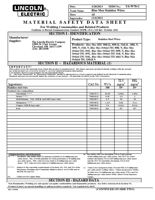
Date: 3/20/2013 MSDS No.: US-W70-CTrade Name: Blue Max Stainless WiresSizes: AllSupersedes: 11/6/2012M A T E R I A L S A F E T Y D A T A S H E E TFor Welding Consumables and Related ProductsConforms to Hazard Communication Standard 29CFR 1910.1200 Rev. October 1988SECTION I - IDENTIFICATIONManufacturer/Supplier:The Lincoln Electric Company22801 St. Clair AvenueCleveland, OH 44117-1199(216) 481-8100Product Type: Stainless Steel WiresProducts: Blue Max MIG 308LSi, 309LSi, 316LSi , 308L N, 309L N, 316L N, Blue Max Orbital TIG 308L N, Blue Max Orbital TIG 308L, Blue Max Orbital TIG 309L N, Blue Max Orbital TIG 309L, Blue Max Orbital TIG 316L N, Blue Max Orbital TIG 316L, Blue Max Orbital TIG 4462 N, Blue Max Orbital TIG 320LR NSECTION II - HAZARDOUS MATERIAL (1)I M P O R T A N T !This section covers the materials from which this product is manufactured. The fumes and gases produced during welding with the normal use of this product are covered by Section V; see it for industrial hygiene information.CAS Number shown is representative for the ingredients listed.(1) The term “hazardous” in “Hazardous Materials” should be interpreted as a term required and defined in the Hazards Communication Standard and does not necessarily imply the existence of any hazard. All materials are listed on the TSCA inventory.Product is inert, no special handling or spill procedures required. Not regulated by DOT.Rev 11/06b (CONTINUED ON SIDE TWO)Product: Blue Max Stainless WiresDate: 3/20/2013SECTION IV - HEALTH HAZARD DATAThreshold Limit Value: The ACGIH recommended general limit for Welding Fume NOS - (Not Otherwise Specified) is 5 mg/m3.ACGIH-1999 preface states that the TLV-TWA should be used as guides in the control of health hazards and should not be used as fine lines between safe and dangerous concentrations. See Section V for specific fume constituents which may modify this TLV. Threshold Limit Values are figures published by the American Conference of Government Industrial Hygienists. Units are milligrams per cubic meter of air.Effects of Overexposure: Electric arc welding may create one or more of the following health hazards:Fumes and Gases can be dangerous to your health. Common entry is by inhalation. Other possible routes are skin contact and ingestion.Short-term (acute) overexposure to welding fumes may result in discomfort such as metal fume fever, dizziness, nausea, or dryness or irritation of nose, throat, or eyes. May aggravate pre-existing respiratory problems (e.g. asthma, emphysema). Chromates present in the fume have beenknown to cause severe irritation of the bronchial tubes and lungs. Asthma has been reported.Long-term (chronic) overexposure to welding fumes can lead to siderosis (iron deposits in lung) and may affect pulmonary function. Manganese overexposure can affect the central nervous system, resulting in impaired speech and movement. Bronchitis and some lung fibrosis have been reported. Nickel and its compounds are on the IARC (International Agency for Research on Cancer) and NTP (National Toxicology Program) lists as posing a cancer risk to humans. Nickel compounds are skin sensitizers with symptoms usually occurring after repeated exposure - ranging from a slight itch to severe dermatitis. Chromates may cause ulceration and perforation of the nasal septum. Liver damage and allergic reactions, including skin rash, have been reported. Chromates contain the hexavalent form of chromium. Hexavalent chromium and its compounds are on the IARC (International Agency for Research on Cancer) and NTP (National Toxicology Program) lists as posing a cancer risk to humans.WARNING: This product contains or produces a chemical known to the State of California to cause cancer and birth defects (or other reproductive harm). (California Health & Safety Code Section 25249.5 et seq.)Arc Rays can injure eyes and burn skin. Skin cancer has been reported.Electric Shock can kill. If welding must be performed in damp locations or with wet clothing, on metal structures or when in cramped positions such as sitting, kneeling or lying, or if there is a high risk of unavoidable or accidental contact with workpiece, use the following equipment: Semiautomatic DC Welder, DC Manual (Stick) Welder, or AC Welder with Reduced Voltage Control.Emergency and First Aid Procedures: Call for medical aid. Employ first aid techniques recommended by the American Red Cross.IF BREATHING IS DIFFICULT give oxygen. IF NOT BREATHING employ CPR (Cardiopulmonary Resuscitation) techniques.IN CASE OF ELECTRICAL SHOCK, turn off power and follow recommended treatment. In all cases call a physician.SECTION V - REACTIVITY DATAHazardous Decomposition Products: Welding fumes and gases cannot be classified simply. The composition and quantity of both are dependent upon the metal being welded, the process, procedure and electrodes used.Other conditions which also influence the composition and quantity of the fumes and gases to which workers may be exposed include: coatings on the metal being welded (such as paint, plating, or galvanizing), the number of welders and the volume of the worker area, the qualityand amount of ventilation, the position of the welder's head with respect to the fume plume, as well as the presence of contaminants inthe atmosphere (such as chlorinated hydrocarbon vapors from cleaning and degreasing activities.)When the electrode is consumed, the fume and gas decomposition products generated are different in percent and form from theingredients listed in Section II. Decomposition products of normal operation include those originating from the volatilization, reaction,or oxidation of the materials shown in Section II, plus those from the base metal and coating, etc., as noted above.Reasonably expected fume constituents of this product would include: Primarily iron oxide, manganese oxide, and complex chromium oxides;secondarily complex oxides of copper, molybdenum and nickel when used with gas shielding.Maximum fume exposure guideline for this product based on manganese content is 0.1 milligrams per cubic meter when used with gas shielding.The OSHA PEL (Permissible Exposure Limit) is a ceiling value that shall not be exceeded at any time.Keep exposure as low as possible. Indoors, use local exhaust; outdoors, a respirator may be required.Gaseous reaction products may include carbon monoxide and carbon dioxide. Ozone and nitrogen oxides may be formed by the radiationfrom the arc.Determine the composition and quantity of fumes and gases to which workers are exposed by taking an air sample from inside the welder's helmet if worn or in the worker's breathing zone. Improve ventilation if exposures are not below limits. See ANSI/AWS F1.1, F1.2, F1.3 and F1.5, available from the American Welding Society, 550 N.W. LeJeune Road, Miami, FL 33126.SECTION VI AND VIICONTROL MEASURES AND PRECAUTIONS FOR SAFE HANDLING AND USE Read and understand the manufacturer's instruction and the precautionary label on the product. Request Lincoln Safety Publication E205. See American National Standard Z49.1, "Safety In Welding, Cutting and Allied Processes" published by the American Welding Society, 550 N.W. LeJeune Road, Miami, FL, 33126 (both available for free download at /community/safety/) and OSHA Publication 2206 (29CFR1910), U.S. Government Printing Office, Superintendent of Documents, P.O. Box 371954, Pittsburgh, PA 15250-7954 for more details on many of the following: Ventilation: Use enough ventilation, local exhaust at the arc, or both to keep the fumes and gases from the worker's breathing zone and the general area. Train the welder to keep his head out of the fumes. Keep exposure as low as possible.Respiratory Protection: Use respirable fume respirator or air supplied respirator when welding in confined space or general work area when local exhaust or ventilation does not keep exposure below TLV.Eye Protection: Wear helmet or use face shield with filter lens shade number 12 or darker. Shield others by providing screens and flash goggles. Protective Clothing: Wear hand, head, and body protection which help to prevent injury from radiation, sparks and electrical shock. See Z49.1.At a minimum this includes welder's gloves and a protective face shield, and may include arm protectors, aprons, hats, shoulder protection, as well as dark substantial clothing. Train the welder not to permit electrically live parts or electrodes to contact skin or clothing or gloves if they are wet. Insulate from work and ground.Disposal Information:Discard any product, residue, disposable container, or liner as ordinary waste in an environmentally acceptable manner accordingto Federal, State and Local Regulations unless otherwise noted. No applicable ecological information available.。
蓄电池12V100Ah技术规范书
(1) (2) (3) (4) (6) (7) (10) (11)................................................ (15)附表一设备关键指标表 (15)附表二技术性能偏差表 (16)附表三备品备件、维护工具和仪器清单 (18)1.1 本招标技术文件合用于蓄电池组供货的功能设计、结构、性能、安装和试验等方面的技术要求。
1.2 本次设备招标范围只包括内蓄电池组主设备及其技术督导服务,主设备包括,涵蓄电池、电池间的专用连线及接线耳等,物资定货范围详见技术规范书专用部份。
1.3 投标方提供的蓄电池组必须具有国家认证或者国际权威认证的检测机构出具的合格证明。
1.4 通信专用蓄电池投标方需通过南方电网公司组织的“2022 年架空地线复合光缆、变电站通信电源、通信专用蓄电池组、 35kV 及以上路线电力载波设备送样检测”,并出具相应检测报告。
1.5 本招标技术文件提出的是最低限度的技术要求,并未对一切技术细节作出规定,也未充分引述有关标准和规范的条文,投标方应提供符合本招标技术文件及本招标技术文件引用的国家标准和行业标准的优质产品。
1.6 投标方所提供的设备应保证是最新生产的设备,并应对涉及专利、知识产权等法律条款承担义务,招标方对此不承担任何责任。
1.7 第三方产品的技术、性能参数、测试数据应由产品生产厂商直接提供和确认,并由投标方对系统整体性能负责。
1.8 投标方应对系统的整体性能负责。
在系统调测和试运行期间,如果发现由于投标方设计或者配置不合理或者缺少设备 (含部件) 而造成整个系统功能不能满足本技术规范书的要求,投标方应负全部责任。
系统投入运行后,如果招标方需修改或者增加系统的功能,投标方有义务提供性能的修改和增加,免费提供软件版本的升级。
1.9 如果投标方没有以书面形式对本招标技术文件的条文提出异议,则意味着投标方提供的设备(或者系统)彻底符合本招标技术文件的要求。
徕卡 TPS1200 技术手册

TPS1200
5
测站信息………………………………………182 电池和内存……………………………………183 系统信息……………………………………...184 接口…………………………………………….186 整平和激光对中……………………………….187 远望镜定位……………………………………..188 功能……………………………………………189 EDM……………………………………………189 棱镜搜索方法--ATR………………………….191 棱镜搜索方法--PS ……………………………194 跟踪移动中的棱镜—锁定…………………..196 RCS……………………………………………198 导向光 EGL……………………………………199 快速设置----SHIFT+USER…………………..200 概述…………………………………………...200 使用罗盘定向………………………………...202 依据角度定位望远镜………………………..204 导航键控制仪器转动…………………………205 检查记录的点…………………………………..206 L.GO/L.INT…………………………………..208
型 号:
机身编号:
软件版本:
仪器标识
2
TPS1200
目录
仪器标识………………………………………………2 目录……………………………………………………3 主菜单……………………………………………….11 管理/作业…………………………………………..12 概述…………………………………………………12 新建作业……………………………………………13 编辑作业……………………………………………14 作业中的编码管理…………………………………15 管理…/数据………………………………………16 概述………………………………………………..16 数据相关术语………………………………………..18 输入已知点……………………………………….23 点的编辑…………………………………………….25 平均页……………………………………………….27 线、面的创建与管理……………………………….31 编辑线、面………………………………………….33 示例…………………………………………………..35 数据日志…………………………………………….37 点、线、面数据排序与过滤………………………39
YS12S16-0G;中文规格书,Datasheet资料
Electrical Specifications (continued)
Conditions: TA=25ºC, Airflow=200 LFM (1 m/s), Vin=12 VDC, Vout = 0.7525 - 5.5V, unless otherwise specified.
PARAMETER INPUT CHARACTERISTICS
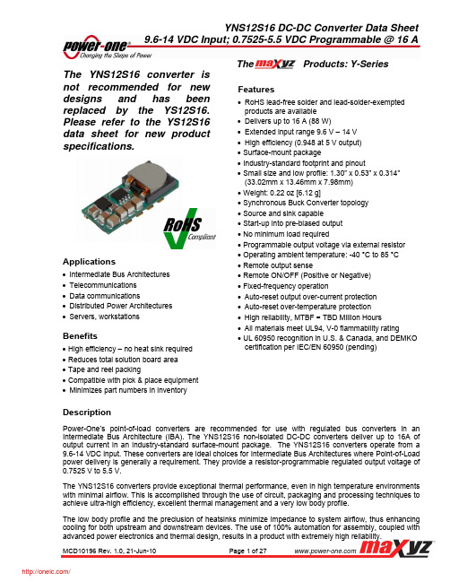
YNS12S16 DC-DC Converter Data Sheet 9.6-14 VDC Input; 0.7525-5.5 VDC Programmable @ 16 A
The Products: Y-Series
The YNS12S16 converter is not recommended for new designs and has been replaced by the YS12S16. Please to the YS12S16 data sheet for new product specifications.
FEATURE CHARACTERISTICS
Switching Frequency Output Voltage Programming Range 1 Remote Sense Compensation Turn-On Delay Time With Vin = (Module Enabled, then Vin applied) With Enable (Vin = Vin(nom) applied, then enabled) Rise time ON/OFF Control (Positive Logic) Module Off Module On ON/OFF Control (Negative Logic) Module Off Module On Note: 1. The output voltage should not exceed 5.5V (taking into account both the programming and remote sense compensation). 2. Converter is on if ON/OFF pin is left open. 3. Note that start-up time is the sum of turn-on delay time and rise time.
BNS 250-12Z-2187 安全传感器 商品说明书
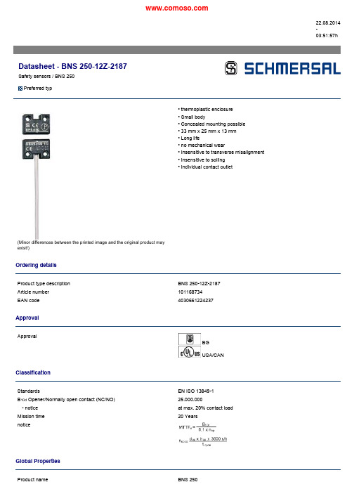
22.08.2014-03:51:57hDatasheet -BNS 250-12Z-2187Safety sensors /BNS 250Preferredtyp(Minor differences between the printed image and the original product may exist!)•thermoplastic enclosure •Small body•Concealed mounting possible •33mm x 25mm x 13mm •Long life•no mechanical wear•Insensitive to transverse misalignment •Insensitive to soiling •Individual contact outletOrdering detailsProduct type description BNS 250-12Z-2187Article number 101168734EAN code4030661224237ApprovalApprovalBG USA/CANClassificationStandardsEN ISO 13849-1B 10d Opener/Normally open contact (NC/NO)25.000.000-notice at max.20%contact load Mission time 20YearsnoticeGlobal PropertiesProduct nameBNS 250Standards IEC60947-5-3,BG-GS-ET-14Compliance with the Directives(Y/N)YesMaterials-Material of the housings Plastic,glass-fibre reinforced thermoplastic -Material of the cable mantle PVCCoding available(Y/N)YesMonitoring function of downstream devices(Y/N)NoPrerequisite evaluation unit YesRecommended safety-monitoring moduleRecommended actuator BPS250Mechanical dataDesign of electrical connection CableCable length1mConductors0,25mm²AWG-Number23mechanical installation conditions not flushActive area front sideEnsured switch distance ON4mmEnsured switch distance OFF14mmType of actuation MagnetDirection of motion head-on with regard to the active surface restistance to shock30g/11msResistance to vibration10…55Hz,Amplitude1mmAmbient conditionsAmbient temperature-Min.environmental temperature−25°C-Max.environmental temperature+70°CStorage and transport temperature-Min.Storage and transport temperature−25°C-Max.Storage and transport temperature+70°CProtection class IP67Electrical dataIntegrated Safety monitoring module available(Y/N)NoCross circuit/short circuit recognition possible(Y/N)YesVoltage type VDCSwitch frequency max.5HzSwitching voltage max.24VDCSwitching current max.100mASwitching capacity max.1WOutputsDesign of control output Other,Reed contaktsNumber of shutters1pieceNumber of openers2pieceElectrical data-Safety outputsNumber of secure semi-conductor outputs0pieceNumber of secure outputs with contact0pieceElectrical data-Diagnostic outputNumber of semi-conductor outputs with signaling function0pieceNumber of outputs with signaling function that already have a contact0pieceLED switching conditions displayLED switching conditions display(Y/N)NoATEXExplosion protection categories for gases NoneExplosion protected category for dusts NoneDimensionsDimensions of the sensor-Width of sensor33mm-Height of sensor25mm-Length of sensor13mmnoticeContact symbols shown for the closed condition of the guard device.The contact configuration for versions with or without LED is identical.Included in deliveryActuators must be ordered separately.DiagramNote Diagrampositive break NC contactactiveno activeNormally-open contactNormally-closed contactOrdering codeBNS250-(1)Z(2)-(3)(1)111Normally open contact(NO)/1Opener(NC)121Normally open contact(NO)/2Opener(NC)(2)without without LED switching conditions displayG with LED switching conditions display(3)2187Individual contact outlet(without LED switching conditions display) DocumentsOperating instructions and Declaration of conformity(en)519kB,15.02.2010Code:mrl_bns250-12z-2187_enOperating instructions and Declaration of conformity(pl)281kB,22.05.2012Code:mrl_bns250-12z-2187_plOperating instructions and Declaration of conformity(es)420kB,07.05.2010Code:mrl_bns250-12z-2187_esOperating instructions and Declaration of conformity(nl)416kB,06.05.2010Code:mrl_bns250-12z-2187_nlOperating instructions and Declaration of conformity(de)835kB,24.09.2010Code:mrl_bns250-12z-2187_deOperating instructions and Declaration of conformity(it)405kB,06.05.2010Code:mrl_bns250-12z-2187_itOperating instructions and Declaration of conformity(jp)498kB,05.07.2011Code:mrl_bns250-12z-2187_jpOperating instructions and Declaration of conformity(pt)280kB,22.05.2012Code:mrl_bns250-12z-2187_ptOperating instructions and Declaration of conformity(da)272kB,27.08.2012Code:mrl_bns250-12z-2187_daOperating instructions and Declaration of conformity(fr)427kB,06.05.2010Code:mrl_bns250-12z-2187_frImagesDimensional drawing(basic component)Characteristic curveSystem componentsActuator101120594-BPS250•thermoplastic enclosureAccessories101131223-SPACER BNS250•to mount the magnetic safety sensor and actuator on ferromagneticmaterial•Suitable for food processing industryK.A.Schmersal GmbH&Co.KG,Möddinghofe30,D-42279WuppertalThe data and values have been checked throroughly.Technical modifications and errors excepted.Generiert am22.08.2014-03:51:58h Kasbase2.2.18.F DBI。
Valor 火器1 3厚度塑料板材料规格说明书

February 20201/3Cement BoardL3 1800KMaterial Speci fi cationsNon-CombustibleMaterial which will not ignite and burn. Such materials are those consisting entirely of steel, iron, brick, tile, concrete, slate, glass or plasters, or any combination thereof.Materials that are reported as passing ASTM E 136, Standard Test Method for Behavior of Materials in a Vertical Tube Furnace at 750°C shall be considered non-combustible materials.CombustibleMaterials made of or surfaced with wood, compressed paper, plant fi bers, plastics, or other material that can ignite and burn, whether fl ame proofed or not, or plastered or unplastered shall be considered combustible materials.Non-Combustible Cement BoardThe L3 Linear fi replace requires a 1/2” (13 mm) thicknon-combustible cement board to be used as a wall surface immediately surrounding the unit’s opening—see diagram for minimum coverage.Extending the cement board well beyond the minimum shown will help avoid cracking due to di ff erential expansion of materials.Pre-drill cement board with oversized holes and do not over-tighten screws to avoid cracking due to heat expansion.Standard gypsum wall board may be used beyond the perimeter of the cement board.Minimum coverage area of non-combustible cement board.inches [mm]With 1850 or 1875 trimswith 1830CIK kitA Min. 25-1/2 [648]Min. 25-1/8 [638]B 14-3/4 [375]15-13/16 [401]C Min. 9-1/4 [235]Min. 8-9/16 [218]D Min. 5-1/16 [129]Min. 4-1/2 [114]EMin. 64 [1626]Min. 65-1/4 [1657]Wall Finish — TrimsWider trim (1850) can adjust up to 1” forward of surface of cement board.Cement board tucks behind trim.Narrow trim (1875) can adjust up to 5/8” forward of surface of cement board.Cement board tucks behind trim.Clean Installation Kit 1830CIK requires HeatShift. Cement board fi nishes up to perimeter of frame. Must install BEFORE cement board.Non-Combustible Finishing Over Cement BoardAdditional non-combustible material such as tile, etc., may be applied over top of the cement board or you may choose to leave it fi nished clean with no tile, etc.Be aware that a trim is always required. Finish should not cover the trims.1875 and 1850 TrimsOnly the 1875 and 1850 style trims will accept tile, etc. tucked behind them (up to 5/8” thick for the 1875 and up to 1 inch thick for the 1850).1830 Trim1830 trim must be installed BEFORE cement board. Cement board and fi nishes are applied to the perimeter of the trim frame. Cement board and fi nish CANNOT betucked under this trim.Wall Finish — Avoid CrackingAvoiding Cracking Wall FinishesWe recommend installing the optional HeatShiftSystem to reduce the wall temperatures and minimize the possibility of cracking wall fi nishes.If a clean fi nish with no tile, etc. is desired, joints in the cement board and the transition to gypsum board will require special attention if future cracking is to be controlled. Be aware that temperatures on the non-combustible wall surface above the appliance can exceed 200°F (93°C).Below are some tips on how to best avoid any cracking:• Allow materials to dry thoroughly before fi nishing the wall. Cement board has the ability to absorb up to 30 percent of its weight in water and may shrink as much as 1/8” over a 48” length when drying from a satu-rated condition. Running the fi replace for an extended period before fi nal fi nishing will help drive out mois-ture.• Always pre-drill screw holes through cement boardand use screws speci fi c for material used.• Always use mesh tape over joints.• Always stagger joints in wall board.• Behind joints, double up studs or use studs “on the fl at” to add extra support to the joint. Adhesive on the backside of wall board behind any joints can help control di ff erential movement.• Use multiple, thinner coats of joint compound and al-low to dry thoroughly between coats.• Ensure framing materials are dry.• After fi nishing the wall, introduce heat gradually to slowly dry any excess moisture rather than drying too fast.• Avoid notching cement board or tiles around corners of window opening and instead provide a joint that intersects the corner.• Avoid using lage one-piece slab of material with a cut-out in the middle as a surround for the fi replace.Expansion above the opening will cause cracking at in-side corners. Provide a joint that intersects the insidecorner to avoid cracking.。
安全帽低温恒温水浸泡预处理箱内容

前言感谢贵公司选择本公司的产品,本公司不仅为贵公司提供质量优良的产品,还将提供可靠、一流的售后服务。
为了确保操作人员的人身安全及仪器的完好性,在使用本仪器前请仔细阅读此操作说明书,着重留意其中有关注意事项。
本说明书详细介绍此仪器的设计原理、相关标准、构造、操作规范、保养方法、常见故障及其处理方法等内容。
本说明书中如有提及各种“试验规定”、“标准”时,均只作参考用。
如贵公司有异议,请自行检阅相关标准或资料。
该仪器在包装运输前工厂工作人员已经进行详细的检查,确保质量合格。
然而尽管其包装能够经受住搬卸和运输所造成的冲击,剧烈的震荡仍可能会损坏仪器,因此收到该仪器后,请仔细检查仪器机体和零配件有无损坏。
如有损坏现象,请贵公司提供一份较为全面的书面报告给本公司的市场服务部门,本公司将为贵公司处理有关损坏设备,保证仪器质量合格。
请依照说明书上的要求进行检查、安装以及调试。
说明书不宜随意丢弃,应妥善保存,以便日后查阅参考!用户在使用本仪器时,如对该仪器设计上的不足及改进有任何的意见和建议,敬请告知本公司。
特别声名:本手册不能作为向本公司提出任何要求的依据。
本手册的解释权在本公司。
安全注意事项1.安全标志:下列标志所提及的内容主要是为了防止意外事故和危险的发生、保护操作人员和仪器以及确保测试结果的精确度,请务必注意!危险此标志表示如不遵照,操作者有可能受伤。
!警告此标志表示如不遵照,有可能损坏仪器。
注意此标志表示有可能影响测试结果的精确度。
注此标志为本产品在操作使用中的辅助说明。
一、主要用途用于安全帽、头盔等的低温预处理和水浸泡预处理。
满足GB/T2812-2006 《安全帽测试方法》。
二、仪器特征及主要技术指标●合金试样架,能牢固的固定各种安全帽试样,操作简单,方便;●PID智能温度控制系统,显示实时温度及设定温度;●试验温度可设定范围:-20℃~ +20℃;●工作电源:AC220V 50Hz 1.5KW三、电气控制箱按钮及显示说明电源开关——按到“1”仪器通电,按到“0”仪器断电温度——显示试验箱体内实时温度和设定的温度即设定的试验需要的温度(PV显示的是实时温度,SV显示的是设定温度)制冷——显示制冷机工作状态,灯亮时表示制冷机正在工作制冷开关——打开或关闭制冷机,按到“1”时为开,按到“0”时为关加热——显示加热管工作状态,灯亮时表示加热管正在工作加热开关——打开或关闭加热管,按到“1”时为开,“0”时为关试验时间——显示和设定试验进行的时间计时开始——按一下此按钮,则试验时间开始计时计时停止——按一下此按钮,则清除试验时间,同时关闭蜂鸣器四、试验前准备工作1、准备试验用安全帽,将安全帽表面擦拭干净。