JTY-HM-GST102线型光束感烟火灾探测器安装使用说明书
海湾电子编码器使用说明书

海湾电子编码器使用说明书海湾电子编码器安装使用说明书一、概述GST-BMQ-2电子编码器(以下简称编码器)可对电子编码的探测器或模块进行地址码、灵敏度、设备类型等的读出和地址码、灵敏度的写入功能,还可以对火灾显示盘进行地址码、灯号及二次码的读出和写入。
二、特点1. 该编码器采用手握式结构,外形小巧,携带方便,操作简单;2. 该编码器可通过编码器后盖的总线接口,直接和总线型探测器旋接,进行编码等操作,更加方便,如图2所示(略);3. 可对公司生产的总线型探测器、模块等设备编码,可对ZF-GST8903火灾显示盘、JTY-HM-GST102线型光束感烟火灾探测器、JTY-HF-GST102线型光束感烟火灾探测器、隔爆点型可燃气体探测器等I?C接口设备编码;4. 四位段码式液晶显示,显示直观;5. 低功耗睡眠和自动关机功能;6. 电池欠压指示功能三、技术特性accident occurs, the direct punishment 500-1000, who is directly responsible for the accident responsibility, give notice of criticism and 50-100 economic sanctions against them. (4) to conceal the accident, reported without undue delay or false, to inform the administrative leadership of the criticism, resulting in serious consequences, the pursuit of leadership, along with 500-1000 punishment. (5) significant near miss should be attempted as the case of responsible for the accident and construction team injuries accident penalty provisions, mutatis mutandis. Eight, should perform in the construction standards and specifications, serial number a 1 GB3323-2005 steel fusion welded butt joints, welding engineering-Ray lighting and quality rating of 2 GB11345-89 steel welds manual methods of ultrasonic inspection and testing results for grade 3 GB50236-2002 industrial pipe welding engineering code for construction and acceptance of field equipment 4 HGJ222-92 technical specification for welding of aluminium and itsalloys 5 low temperature steel welding procedure 6 SH3525-2004 petrochemical JB/ T4708-2000 of welding procedure qualification forsteel pressure vessels 7 JB/4709-2000 8 JB4730-2005 pressure vessel welding procedures of steel pressure vessel NDT 9 JB/T4744-2000 steel pressure vessel products mechanical properties test of welded plate II, mechanical equipment installation engineering 1 GB150-98 2 GB50128-2005 vertical cylindrical steel pressure vessel steel welding specification for construction and acceptance of oil tank 3 JB/ T4735-1997 steelwelded atmospheric pressure vessel 4 GB50231-2009 mechanical equipment installation1. 电源:1节9V叠式电池2. 工作电流?8mA3. 待机电流?100чA4. 使用环境:温度:-10?~+50?相对湿度?95%,不凝露5. 尺寸:164mm×64mm×37mm四、结构特征外形示意图如图1所示(略) 1:电源开关 2:液晶屏3:总线插口 4:火灾显示盘接口(I?C) 5:复位键 6:固定螺丝7:电池盒后盖 8:铭牌9:JTY-GD-G3、JTY-ZCD-G3N探测器总线接口 10:JTY-GM-GST9611、JTW-ZOM-GST9612型探测器总线接口11:电池盒后盖螺丝 12:保护盖其中各部分名称和功能说明如下:accident occurs, the direct punishment 500-1000, who is directly responsible for the accident responsibility, give notice of criticism and 50-100 economic sanctions against them. (4) to conceal the accident, reported without undue delay or false, to inform the administrative leadership of the criticism, resulting in serious consequences, the pursuit of leadership, along with 500-1000 punishment. (5) significant near miss should be attempted as the case of responsible for theaccident and construction team injuries accident penalty provisions, mutatis mutandis. Eight, should perform in the construction standards and specifications, serial number a 1 GB3323-2005 steel fusion welded butt joints, welding engineering-Ray lighting and quality rating of 2 GB11345-89 steel welds manual methods of ultrasonic inspection and testing results for grade 3 GB50236-2002 industrial pipe welding engineering code for construction and acceptance of field equipment 4 HGJ222-92 technical specification for welding of aluminium and its alloys 5 low temperature steel welding procedure 6 SH3525-2004 petrochemical JB/ T4708-2000 of welding procedure qualification for steel pressure vessels 7 JB/4709-2000 8 JB4730-2005 pressure vessel welding procedures of steel pressure vessel NDT 9 JB/T4744-2000 steel pressure vessel products mechanical properties test of welded plate II, mechanical equipment installation engineering 1 GB150-98 2 GB50128-2005 vertical cylindrical steel pressure vessel steel welding specification for construction and acceptance of oil tank 3 JB/ T4735-1997 steel welded atmospheric pressure vessel 4 GB50231-2009 mechanical equipment installation1. 电源开关:完成系统硬件开机和关机操作。
GST102GST104多线制火灾报警控制器安装使用说明书

GST102 GST104 Conventional Fire Panel Installation and Operation Manual(Issue 2.01, January 2005)CONTENTS1 General (1)2 Technical Specifications (1)2.1 Operating Voltage (1)2.2 Standby Batteries (1)2.3 Parameters of Detection Circuit (1)2.4 Parameters of Output Circuit (1)2.5 Dimension (2)3 Structure (2)3.1 Appearance (2)3.2 Internal Structure (3)3.3 Terminals (3)3.4 Operating Panel (4)3.4.1 General State LEDs (4)3.4.2 Zone State LEDs (5)3.4.3 Operation State LEDs and Keys (5)3.4.4 Output State LEDs (6)3.5 Operating State (6)3.5.1 Zone State (6)3.5.2 Output State (7)3.5.3 Internal Buzzer (7)3.5.4 Illustration (7)3.6 System Setting (7)3.6.1 Setting of Operation Level (7)3.6.2 Setting of Relay Output (8)4 Operation (9)4.1 Basic Operation (9)4.1.1 Silencing of Fault and Fire Alarm (9)4.1.2 Day/Night Working Mode (9)4.1.3 Self-check and Fire Alarm Clearance (9)4.1.4 Control of External Sounders (9)4.2 Setting of Isolation State (10)4.3 Setting of Test State (14)4.4 Setting of Output System (15)4.4.1 Setting of Sounder 1 (15)4.4.2 Setting of Sounder 2 (15)4.5 Setting of Ground Fault and Aux. Power (16)4.6 Wiring of detectors, manual call points and output circuits and signal output interface board with passive normally open alarm output contact and fault output contact (16)4.7 Wiring Diagrams (17)4.8 Calculation of Standby Battery Capacity (19)5 Troubleshooting (19)A ppendix AEOL P-9907 Operation Instruction (21)1 GeneralThese two kinds of conventional fire panel are multi-wire fire panel developed from microprocessor. GST104 Conventional Fire Panel (hereinafter called GST104 panel)can monitor 4 zones. GST102 Conventional Fire Panel (hereinafter called GST102panel) can monitor 2 zones. Those with signal output interface board has a passivenormally open alarm output contact and fault output contact for each zone. Each zonecan be connected with 15 conventional fire detectors. They have two external controloutput points to control some devices such as sounder strobe and sounder etc. Thestated maximum load is two sounder outputs. They are designed with internal standbybatteries and space for installation (two sealed acid storage batteries). They havefunctions of test and isolation, setting day/night mode, indication of normal state, faultstate, alarm state, alarm of short circuit and open circuit of external connections andidentifying the location of the detecting zone. The installation and operation of the twokinds of panel are very simple and convenient. All the control functions can be realizedthrough a key switch, and the programming function can be realized through a keyswitch and an internal switch. Except for two monitoring zones (two zone input) less, two passive normally open alarmoutput contacts and two passive normally open fault output contacts less for those withsignal output interface board, and some minor differences in appearance and structure,GST102 panel is the same as GST104 panel in technical specifications, usage andoperation. We will take GST104 panel as the example.2 Technical Specifications2.1 Operating Voltage220VAC ±15%, 50Hz 24VDC ±15%2.2 Standby BatteriesThe capacity of the standby batteries is outfitted according to the user’s demandcomputed with reference to Section 4.8. The maximum capacity is 7Ah (lasting for 24hours in normal monitoring state).2.3 Parameters of Detection CircuitOutput Voltage: 20VDC~28VDCStatic Loading Current: 2.4mA (when connected with 15 conventional detectors)Fire Alarming Resistance: 150Ω - 1.5kΩ (normally 470Ω)Terminal Resistor: 4.7 kΩ or AEOL (Active End of Line Unit)2.4 Parameters of Output CircuitSounder Output: Output Voltage 20VDC~28VDCOutput Current 1ATerminal Resistor 4.7 kΩAux. Power Output: 0.5A 20VDC~28VDC2.5 Dimension380mm x 320mm x 95mm 3 Structure3.1 Appearance3.2 Internal StructureFig. 3.2.1Illustration:1. Power2. Storage Battery 4. 6.Fig. 3.3EARTH : Terminal connected with chassis earth AUX SUPPLY (+,-): AUX. Power terminals ZONE INPUT (1~4): Zone input terminalsBAT (+,-): Storage battery terminals 220VAC (N , ,L ): Main power terminals SOUNDER OUTPUT (1~2): Sounder output terminals SOUNDER START (+,-): Sounder startup terminals DAY MODE (+,-): Day mode conversion terminalsFAULT1~FAULT4: Fault output terminal of signal output interface board, which is a normally open contact output in normal state, and will be closed after it alarms fault.ALARM1~ALARM4: Alarm output terminal of signal output interface board, which is a normally open contact output in normal state, and will be closed after it alarms fire.COM 0V: Power earth of repeater panelCOM DAY: Day mode terminal of repeater panel COM FIRE: Fire alarm terminal of repeater panel COM ISO: Isolation terminal of repeater panel FLT: Fault terminal of repeater panelZ1~Z4: Zone indication terminals of repeater panel3.4 Operating PanelNote: Area of white background with dark dots is to be illustrated presently. 3.4.1 General State LEDsFig. 3.4.1Zone Fault/ISO/TestFIRE Silence FaultCommonFaultIsolate Common Fault C.P.U Fault Battery Fault TestModeSupply Power Ground In Day PowerFIRE — Red, general fire alarm LED. Constantly lit until the fire alarm is cleared.Silence — Yellow, general silencing LED. Constantly lit when the internal buzzer orsounder is silenced.Common Fault — Yellow, general fault LED. Flashing when any fault is found andconstantly lit after the “Silence” key is pressed.Common Isolate — Yellow, general isolation LED. Constantly lit when any zone oroutput is isolated.C.P .U Fault — Yellow, CPU LED. Flashes when the CPU is in fault state, constantly litwhen the memory checks errors.Power Fault — Yellow, main power fault LED. Constantly lit when the main power is infault.Battery Fault — Yellow, standby power fault LED. Constantly lit when the standbybattery is in fault.Ground Fault — Yellow, ground fault LED. Constantly lit when ground is in fault. In Test — Yellow, test LED. Constantly lit when any zone is in test.Day Mode — Yellow, day mode LED. Constantly lit when the panel works at day mode. Power Supply — Green, power supply LED. Constantly lit when power supply isnormal. 3.4.2 Zone State LEDsFire — Red, zone fire alarm LED. Flashes when the corresponding zone is in fire alarmstate, constantly lit when “Silence” key is pressed.Zone Fault/ISO/Test — Yellow LED. Flashes when the corresponding zone is in fault ortest state, constantly lit in isolation state. 3.4.3 Operation State LEDs and KeysFig.3.4.2 12Zone Fault/ISO/TestZone No.Fire34Fig. 3.4.3 Isolate — Green LED. Constantly lit when setting isolation. Test — Green LED. Constantly lit when setting test.Select — Used to enter programming state and select operation. Shift — Used to change state. Enter — Used to acknowledge.Reset — Executing clear or reset operation.Silence —Changing the silencing state of the interior buzzer and the sounder. 3.4.4 Output State LEDsFig. 3.4.4Sounder 1 — Yellow. Constantly lit when sounder 1 outputs, flashes when it's in fault. Sounder 2 — Yellow. Constantly lit when sounder 2 outputs, flashes when it's in fault. 3.5 Operating State 3.5.1 Zone State1) Alarm: "Fire" LED of corresponding zone flashes (1:1), general "FIRE" LED lit.Silence ResoundReset Isolate TestOperating Select <Shift> Day/Night Enter IndicationSounder1Sounder2Passive fire alarm output contact for corresponding zone of GST104 panel with signal output interface board is closed.2) Fault: "Fault" LED in corresponding zone and "Common Fault" LED flash("Common Fault" LED constantly lit when “Silence” key is pressed). Passive fault output contact for corresponding zone of GST104 panel with signal output interface board is closed.3) Isolate: Zone "Fault" LED and "Common Isolate" LED lit. 4) Normal: Zone "Fire" LED and "Fault" LED not lit.3.5.2 Output State1) Action: LED of corresponding output channel is lit.2) Fault: LED of corresponding output channel flashes, "Common Fault" LED flashes("Common Fault" LED constantly lit when “Silence” key is pressed). 3) Normal: All output channel LEDs go out.3.5.3 Internal Buzzer1) Internal buzzer vocalizes according to sound priority. Alarm: level 0; Fault: level1;Isolation and test: level 2; Normal: level 3.2) Alarm or manually activation of the external sounder: 0.25s on, 0.25s off. 3) Fault state: 0.5s on, 4.5s off.4) Silence, isolation or testing state: 0.5s on, 9.5s off.3.5.4 Illustration1) Operation enabled at low operation level is enabled at high operation level. 2) In keyboard operation mode, when the operation level is changed or no key ispressed for more than four minutes, the panel cancels all keyboard operation input and returns to the normal monitoring state. 3) Conditions of delay output of a certain zone:a) The zone is programmed as delay output mode. b) The panel is in day mode.c) There are no fire alarms in other zones.d) When the zone is in delay mode and there are fire alarms in other zones, it willbe canceled and start output immediately.4) When the memory is in fault, isolation is to be set again.5)3.6 System Setting3.6.1 Setting of Operation Level1) As in Fig. 3.6.1.1, when the “Control Enable” lock points to “O”, the panel is inoperation level 1.Fig. 3.6.1.12) As in Fig. 3.6.1.2, when the “Control Enable” lock points to “I”, the panel is inoperation level 2.3) When the cover of the controller is open, the panel is in operation level 3. 3.6.2 Setting of Relay Output1) Three output modes can be set for the two-channel sounder output relay: activeoutput, normally open contact output and normally closed contact output.a) Sample: To set sounder 1 as active output, plug in fuse F2; connect the 5th with6th and the 2nd with 3rd of jumper X1 by short loop (location of the parts is in Fig. 3.6.2).b) Sample: To set sounder 1 as normally open contact output, remove fuse F2,connect the 1st with2nd and 4th with 5th of the jumper X1 by short loop (location of the parts is in Fig. 3.6.2).c) Sample: To set sounder 1 as normally closed contact output, remove fuse F2,connect the 1st with 2nd and 3rd with 4th of the jumper X1 by short loop (location of the parts is in Fig. 3.6.2).2) Detailed operations are shown in Table 1.Fig. 3.6.1.2Fig. 3.6.2Table 1Normally closed Contact Normally open Contact Active OutputOutput Removed Fuse Jumper Removed Fuse Jumper Removed FuseJumperSounder 1 F2 X1/ 3&4,1&2 F2 X1/5&4,1&2 X1/5&6,2&3Sounder 2 F3 X2/ 3&4,1&2 F3 X2/5&4,1&2 X2/5&6,2&34 Operation4.1 Basic Operation4.1.1 Silencing of Fault and Fire Alarm1) Silencing of fault and fire alarm is processed in operation level 2.2) In fault state, press “Silence” key, the internal buzzer and the sounder are in silencemode, the "Silence" LED is lit; Press “Silence” key again, the buzzer returns to non-silencing state and the silence LED goes out. 3) In fire alarm state, press “Silence” key to acknowledge the fire alarm first. If the firealarm in one zone has been acknowledged, the "Fire" LED of that zone turns from flashing to constantly lit. After all the fire alarms are acknowledged, press “Silence” key to change the silencing state of the internal buzzer and external sounder. 4.1.2 Day/Night Working Mode1) Day/night working mode is related to delay output. There are two methods tochange the Day/Night working mode. 2) Shorting the “DAY MODE” input terminal can enforce the panel into night mode. 3) At operation level 2, press “shift” key for 1 second to change Day/night mode. If daymode is selected, "DAY MODE" LED is lit. 4) Note: If the panel works in day mode for over 18 hours, it will change to night modeautomatically. At the same time, the "DAY MODE" LED flashes. The panel turns into fault. At level 2, press “Reset” to clear the fault. 4.1.3 Self-check and Fire Alarm Clearance1) Self-check and fire alarm clearance is in operation level 2.2) Press “Reset” for 1 second to clear fire alarm in alarm state, to self-check the soundand LEDs in other states and to clear test and fault state. 4.1.4 Control of External Sounders1) As in Fig. 4.1.4.1, when the “Evacuate” lock points to “I”, the 2-channel externalsounder is activated.Fig. 4.1.4 .12) As in Fig. 4.1.4.2, when the “Evacuate” lock points to “O”, the external sounder4.2 Setting of Isolation State1) Isolation state setting is valid for the four detecting zones.2) Rotate the “CONTROL ENABLE” lock to “I”, press “Select” key for 1 second, the“Isolate” LED flashes; Press “Enter”, the “Isolate” LED becomes constantly lit and enters isolation setting state (see Fig. 4.2a – 4.2d).Fig. 4.1.4.2Select Enter3) Press “Select” to select one zone, press “Shift” to change the isolation state of theselected zone. The isolation state is indicated by the "Fault" LED of the corresponding zone, which is off in normal state and constantly lit in isolation state. The “Fire” LED of the corresponding zone, which flashes when selected, indicates th zone (Fig. 4.2e and 4.2f).Fig. 4.2eSelect Fig. 4.2d4) Press “Enter” to exit and save the setting (see Fig. 4.2g).Day/Night Fig. 4.2f EnterFig. 4.2gReset Fig. 4.2h4.3 Setting of Test State It is set in operation level 2.1) Press “Select” key for 1 second, “Isolate” LED flashes. See Fig. 4.2a – 4.2c.2) Press "Shift" key once, "Test" LED flashes. When it flashes, press "Enter", it isconstantly lit and the panel enters test state setting (Fig. 4.3a). EnterDay/NightSelectDay/Night3) Press “Select” key to select the testing zone (see Fig. 4.3b and 4.3c, for example, toalarms fire.3) Code Switch 2 at “ON” means sounder 1 outputs immediately. 4) Code Switch 2 at “OFF” means sounder 1 outputs delayed.4.4.2 Setting of Sounder 2Code Switch 3 and 4 are used to set sounder 2.1) Code Switch 3 at “ON” means sounder 2 outputs when any detecting zone alarmsFig. 4.3cfire.2) Code Switch 3 at “OFF” means sounder 2 outputs only when the 2nd detecting zonealarms fire.3) Code Switch 4 at “ON” means sounder 2 outputs immediately. 4) Code Switch 4 at “OFF” means sounder 2 outputs delayed.4.4.3 Delayed time is 1 minute.4.5 Setting of Ground Fault and Aux. Power1) Connecting jumper X8 with short loop (location of the parts is in Fig. 3.6.2) cancheck Ground fault; Otherwise, not to check Ground fault.2) Selecting the output mode of Aux. Power: Connecting 1 with 2 of jumper X9 asconstant output; Connecting 2 with 3, the system stops for 3 seconds when it resets in fire alarm state (location of the parts is in Fig. 3.6.2). 4.6 Wiring of detectors, manual call points and output circuits and signal outputinterface board with passive normally open alarm output contact and fault output contact 1) The specification of wires allowed for the terminals is cross section within 0.5mm 2~2.5mm 2.2) Taking electromagnetic compatibility into consideration, shielded cable is used inthe system. Keep the shield cover reliable 360o contact with the chassis when installing.3) Each circuit can be connected with 15 conventional fire detectors and infinitemanual call points. There are two methods of connection.a) In the circuit, connect all the manual call points in front of the detectors andconnect a 4.7 k Ω resistor at the end of the circuit. See Fig. 4.6.3.1.4.7k Resistor470Ω(normal)470Ω(normal)Zone Input TermsPanelMCPMCPNO DIODEFig. 4.6.3.1b) In the circuit, connect the fire detectors and manual buttons at any locationand connect AEOL at the end of the circuit. Connect a diode on the base of the fire detectors. See Fig. 4.6.3.2.4.7k Resistor470Ω(normal)470Ω(normal)Zone Input TermsPanelMCPMCPNO DIODEFig. 4.6.3.24) Connection of output circuit: the connected sounders or remote devices shouldhave polarity and be connected according to the polarity of the terminals. Connect the 4.7 k Ω resistor in parallel at the end of the circuit.5) Wiring of signal output interface board has a passive normally open alarm outputcontact and fault output contact: Connect with passive input contact of remote devices without considering polarity. 4.7 Wiring Diagrams4.7.1 Typical WiringFig. 4.7Illustration:SOUNDER OUTPUT :Sounder output WIRED SIMILARLY :Similar wiring FIELD DEVICES :Detectors ZONE INPUT (1~4):Zone inputCOM 0V: Power earth of repeater panelCOM DAY: Day mode terminal of repeater panel COM FIRE: Fire alarm terminal of repeater panel COM ISO: Isolation terminal of repeater panel FLT: Fault terminal of repeater panelZ1~Z4: Zone indication terminals of repeater panel AEOL :Active End of Line UnitVOLT-FREE CONTACT :Active contact EMI FILTER :Filter PSU :PowerTO DISPLAY BOARD :To display board BATT :Standby battery terminal4.7.2 Wiring Diagram with Signal Output Interface BoardFig. 4.84.8 Calculation of Standby Battery Capacity 1) Battery voltage: 24V 2) Power supplyTable 2 PSU capacityMaximum current of output circuitCapacity of internal battery2.0A1.0A 7AhStandby battery works in normal monitoring state (I1)Table 3Current of standby battery (A) Quantity Current Total Current Installing all the Detectors 1 0.13 A 0.13 A Output of Aux. Power Standby battery works in alarming state (I2)Table 4Current of standby battery (A) Quantity Current Total current All the zones in alarming state 0.50 A 0.50 A Sounder output Aux. Power outputSuppose C as the required minimum capacity and T as the time that the battery works in normal monitoring state (unit: hour). Suppose I1 as the total current in normal monitoring state and I2 as the total current in alarming state. Then the battery capacity can be calculated by the formula as follows:C = 1.25[(I1 x T) + I2]Ah5 TroubleshootingTable 5FaultDisposal and CauseAll the LEDs are dark after power upWith +24V output, no +5V outputCheck N7 (3M03) and periphery circuit No +24v output, no +5v outputCheck the fuse F7 of the main board broken or not.Check relay K7 of the main board and its peripheral circuit.No fault reporting of main power and standby battery Check N6 of the main board and its peripheral circuit.Wrong judgment of zone state or output checking state Wrong alarms of many zones: Measure the voltage at VREF_H ofthe main board normal or not. It can be figured out according to the power voltage +24V (really measured) and resistor R67 and R60. Normally, when the power voltage is +27V, the voltage here is 3.65V.Wrong alarming of fault of many zones:Measure the voltage of VREF_L of the main board normal or not. It can be figured out according to the power voltage +24V (really measured) and resistor R68 and R61. Normally, when the power voltage is 27V, the voltage here is 1.0V.Measure the voltage at VREF_S of the main board normal or not. It can be figured out according to the power voltage +24V (really measured) and resistor R58 and R6. Normally, when the power voltage is 27V, the voltage here is 24.7V.Wrong alarming of fault of many output circuits:Measure the voltage of VREF_H ofthe main board normal or not.Check the setting of contact pin X1 – X2 right or not and the fuse F2 – F3 be placed right or not.Not saving the result of setting D9 (24LC02) on the display board isdamaged.Failure of manual lock or certain key D1 on the display board loose contacted tothe socket.Appendix AEOL P-9907 Operation Instruction1 Technical Specifications1) Technical Specifications:Range of Operating Voltage: DC15V~DC28VRating Voltage: DC24VEquivalent Resistor: 4.7kΩOperating Current≤5mA2) Operating Environment:Temperature: -10℃~+50℃3 Mounting and Wiring1) Wiring is as follows:of the zone bus to terminal “3”.b) If the AEOL is not installed with detectors, then connect the anode of zone busto terminal “2” and the cathode of the zone bus to terminal "3”.3) Cautionsa) The polarity of zone bus should not be reverse.b) When the detector is removed, make sure the diode be in sequence in thecircuit.GST ChinaGulf Security Technology Co., Ltd.No. 80, Changjiang East Road, QETDZ, Qinhuangdao, Hebei,P. R. China 066004Tel: +86 (0) 335 8502528Fax: +86 (0) 335 8508942Email: s ales@w GST UKGlobal System Technology PLCStaunton Harold Hall, Staunton Harold Ashby-de-la Zouch, Leicestershire, England LE65 1RTT el :+44 (0)1530 564764F ax :+44(0)1530 564769Rigional OfficePO Box 17998 Unit ZA04 JEBEL ALI Free Zone,Dubai, UAETel: +971 (0) 4 8833050Fax: +971 (0) 4 8833053Email: tech.support@w 。
独立式光电感烟火灾 探测报警器 产品说明书
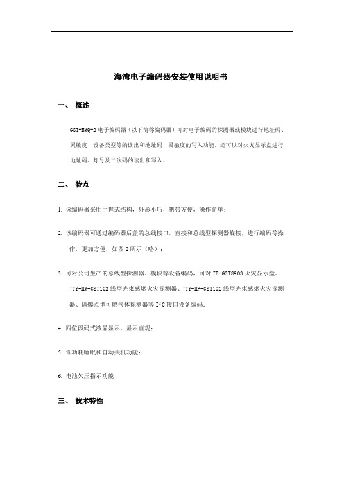
独立式光电感烟火灾探测报警器独立式光电感烟火灾探测报警器,通过感知烟雾来探测火灾。
采用特殊结构设计的光电传感器,利用烟雾中散射的光强度来判断是否有烟雾。
当烟雾达到一定的浓度,即光接收元件接收到的光强度达到预定的阈值时,探测器将发出声光报警信号,火警指示灯(红色)闪烁,并启动蜂鸣器报警。
该产品能有效地探测出火灾在初期阴燃产生的可见烟雾,使用户及时排除险情或进行人员撤离,适用于家居、学校、商店、工厂、酒店等各类场合。
1. 取出报警器、说明书、电池和安装包。
2. 旋转报警器的底板,取下底板。
3. 在天花板上用冲击钻打两个安装孔,用膨胀管和自攻螺钉固定报警器的底板,建议每个房间安装一个探测器。
4. 取出3V电池,插入连接器后,将电池装入电池槽内(切勿撕掉透明膜)。
安装好后按住测试按键,报警器指示灯每2秒闪烁并发出报警声,松开测试按键,灯闪烁及报警声停止,则表明报警器正常工作。
1. 建议每隔三个月对产品进行清洁。
清除污垢时,请用布浸湿水或肥皂水充分拧干后擦拭;清除灰尘时,请用吸尘器沿进烟槽进行清理。
2. 若在使用过程中遇到故障不能正常工作,请尽快与供应商联系,不要私自拆卸修理,以免发生意外。
3. 建议每月按测试键测试一次功能是否正常。
模拟报警测试功能:按住测试按键,报警器报警指示灯每2秒以红色闪烁,并持续发出洪亮的报警声,松开测试按键,灯闪烁及报警声停止,则报警器正常工作。
故障报警功能:报警器会自动检测功能是否正常,如不能正常检测烟雾(故障时),则每隔35秒连续发出2次报警声,报警指示灯以黄色闪烁。
请联系经销商或客服,尽快检测或维修。
低电量报警功能:电池电量不足时,报警器会每隔35秒连续发出3次报警声。
请尽快更换电池。
进烟口外壳底板正常工作状态:报警器指示灯以每300秒红色闪烁,报警器不发声。
火灾报警功能:当烟雾浓度达到报警值时,报警器指示灯以每2秒红色闪烁,并持续发出洪亮的报警声。
如已排除险情,可以按消音/测试按键使报警器消音。
30303560 JTY-HF-GST102线型光束感烟火灾探测器安装使用说明书F3.780.194AS V4.01

JTY-HF-GST102线型光束感烟火灾探测器安装使用说明书(Ver.4.01, 2007.02)海湾安全技术有限公司目录一、概述 (1)二、特点 (1)三、技术特性 (2)四、结构特征与工作原理 (3)五、安装与布线 (6)1.安装探测器的外界条件 (6)2.安装高度及位置说明 (7)3.安装 (9)4.布线 (13)六、调试 (14)七、注意事项 (15)八、使用及操作 (15)1.信息的读取 (16)2.灵敏度级别的写入 (16)3.设备类型的写入 (16)4.探测器的其它功能说明 (17)九、常见故障及维修 (17)十、维护保养 (18)十一、备附件 (19)附录一警告 (20)附录二质量保证 (21)一、概述JTY-HF-GST102线型光束感烟火灾探测器(以下简称探测器)为非编码型反射式线型红外光束感烟探测器。
该探测器必须与反射器配套使用,但需要根据二者间安装距离的不同决定使用一块或四块反射器。
探测器内置性能卓越的单片机,具备强大的分析判断能力,通过在探测器内部固化的运算程序,可自动完成系统的调试、火警的判断和故障的判断,并通过指示灯和信号输出端子给出状态指示。
该探测器还具有根据外界环境参数变化补偿的功能,降低了探测器对现场环境洁净程度的要求,探测器的灵敏度可通过电子编码器进行现场设置,拓宽了本产品的应用场所。
探测器采用全新的、合理的结构设计,调节灵敏、定位准确、外形美观,易于安装,调试方法简单、方便。
该探测器可用于历史性建筑、仓库、大型存储区、购物广场、健身中心、体育馆、展览馆、酒店大堂、印刷厂、制衣厂、博物馆、监狱等场所,还可用于有轻微烟尘的空间。
二、特点1.工作电压范围宽、保护面积大;2.探测器将发射部分、接收部分合二为一,安装简单、方便,光路准直性好;3.内置微处理器,智能化火警、故障判断;4.具有自动校准功能,确保可以由单人在短时间内完成调试,操作简单、方便;5.具有自诊断功能,可以监测探测器的内部故障;6.具有自动补偿功能,对于一定程度上的灰尘污染、位置偏移及发射管的老化等致使接收信号减小的因素可自动进行补偿;7.具有火警、故障无源输出触点;8.可现场设置三个级别的灵敏度;9.探测光路设计巧妙,抗干扰性能强;10.采用SMT工艺;11.外形美观大方,已获国家专利,专利号为ZL 033580537。
光束感烟产品安装使用说明书(3.3C)

目录一、产品概述 (1)二、特点 (1)三、工程设计 (1)四、技术参数 (3)五、安装、调试 (5)1. 探测器外观示意图 (5)2. 安装 (5)3. 连线 (6)4. 调试 (6)5. 检测 (7)六、一般性故障的查询表 (7)七、日常维护 (8)八、售后服务 (8)一、产品概述JTY-HF-YJLH103型线型光束感烟火灾探测器(以下简称探测器)由发射器和接收器组成,采用不受烟色影响的红外线减光方式工作。
单片计算机通过在探测器内置CPU的固化运算程序,使探测器具备了较强的分析判断能力,可自动完成对外界环境变化补偿并判断火警/故障状态,通过声光和输出信号等手段给出状态指示。
特别适用于无遮挡空间的高层建筑群,如各类商场、厅堂馆所、古建筑物、大型车间、仓库、隧道、及各种建筑的夹层、闷顶等,凡是在火灾形成前有烟雾出现的场所均可使用本产品。
当烟雾进入探测区内时,由于光束被遮挡使收到的红外光的强度降低。
当烟雾达到一定浓度使红外光的强度低于设定的阈值时,探测器报火警,启动蜂鸣器、点亮红色指示灯。
本设备功能执行GB14003-2005国家标准中相关条款。
二、特点探测器内所有器件、导线均采用直焊方式连接,无任何接插件,防止温/湿度变化带来的影响,保证探测器在高空长期可靠运行;密闭外壳,具有防尘防水性;可大角度安装,更好的适用于在不平行、弧形、斜型等墙面,拱顶、 斜顶等建筑;轴向单一预压紧调试螺母,调试方便且紧固时不会改变已调好角度; 根据现场调试情况自动修正灵敏度,保证探测器的一致性;接收器设有红、黄指示灯及音响指示,工程调试简便可靠;具有光照自动监测补偿功能,有较强的抗日光干扰能力;具有积尘自动监测补偿功能;多种输出接口,与各厂家报警输入模块配套方便;三、工程设计根据《新编消防设计规范汇编(一)》、《火灾自动报警系统设计规范》GB50116-98中的规定:第7.3.1条:线型火灾探测器的选择:无遮挡大空间或有特殊要求的场所,宜选择红外光束感烟探测器。
海湾电子编码器使用说明书
海湾电子编码器安装使用说明书一、概述GST-BMQ-2电子编码器(以下简称编码器)可对电子编码的探测器或模块进行地址码、灵敏度、设备类型等的读出和地址码、灵敏度的写入功能,还可以对火灾显示盘进行地址码、灯号及二次码的读出和写入。
二、特点1. 该编码器采用手握式结构,外形小巧,携带方便,操作简单;2. 该编码器可通过编码器后盖的总线接口,直接和总线型探测器旋接,进行编码等操作,更加方便,如图2所示(略);3. 可对公司生产的总线型探测器、模块等设备编码,可对ZF-GST8903火灾显示盘、JTY-HM-GST102线型光束感烟火灾探测器、JTY-HF-GST102线型光束感烟火灾探测器、隔爆点型可燃气体探测器等I²C接口设备编码;4. 四位段码式液晶显示,显示直观;5. 低功耗睡眠和自动关机功能;6. 电池欠压指示功能三、技术特性1. 电源:1节9V叠式电池2. 工作电流≤8mA3. 待机电流≤100чA4. 使用环境:温度:-10℃~+50℃相对湿度≤95%,不凝露5. 尺寸:164mm×64mm×37mm四、结构特征外形示意图如图1所示(略)1:电源开关 2:液晶屏3:总线插口 4:火灾显示盘接口(I²C)5:复位键 6:固定螺丝7:电池盒后盖 8:铭牌9:JTY-GD-G3、JTY-ZCD-G3N探测器总线接口10:JTY-GM-GST9611、JTW-ZOM-GST9612型探测器总线接口11:电池盒后盖螺丝 12:保护盖其中各部分名称和功能说明如下:1. 电源开关:完成系统硬件开机和关机操作。
2. 液晶屏:显示有关探测器的一切信息和操作人员输入的相关信息,并且当电源欠压时给出指示。
3. 总线插口:编码器通过总线插口与探测器或模块相连。
4. 火灾显示盘接口(I²C):编码器通过此接口与ZF-GST8903火灾显示盘或以I²C编程方式编码的探测器相连。
线型光束感烟火灾探测器
线型光束感烟火灾探测器JTY-H-VDC1382A线型光束感烟探测器(100米)一、JTY-H-VDC1382A线型光束感烟探测器(50米)的产品概述:1、线型光束感烟探测器由发射、接收器和反光板两部分组成;2、探测器为线型光束感烟探测器;3、线型光束感烟探测器自身无地址,需要配接专用接口JBF-137D模块接入系统;4、适用于大面积、长距离的空间;5、不适用于剧烈振动的墙壁上安装;6、发送器和接收器之间的探测距离为50M或100M。
7、探测器可提供无源开关量报警信号输出;8、调试时应使用VPT3601A专用调试工具;二、JTY-H-VDC1382A线型光束感烟探测器(50米)的技术指标:1、电源电压:19-28V2、工作电流:15mA(含报警状态)3、工作原理:减光型4、报警减光率:30%, 40%, 50%, 60%5、保护距离:50米6、执行标准:GB14003-2005三、JTY-H-VDC1382A接线图JTY-HF-GST102线型光束感烟火灾探测器一、JTY-HF-GST102特点JTY-HF-GST102型线型光束感烟火灾探测器为非编码型反射式线型红外光束感烟火灾探测器。
探测器必须与反射器配套使用,但需要根据二者间安装距离的不同决定使用一块或四块反射器。
探测器主要具有以下特点:(1)将发射部分、接收部分合二为一,安装简单、方便,光路准直性好;(2)具有自动校准功能,确保可以由单人在短时间内完成调试,操作简单、方便;(3)具有自诊断功能,可以监测探测器的内部故障;(4)具有自动补偿功能,对于一定程度上的灰尘污染、位置偏移及发射管的老化等致使接收信号减小的因素可自动进行补偿;(5)可现场设置三个级别的灵敏度,适用于不同扬尘程度的场所;(6)具有火警、故障无源输出触点;(7)探测光路设计巧妙,抗干扰性能强;(8)密封设计,具有防水性能;(9)专利产品,专利号为ZL03358053.7。
JTY-HM-GST102 线型光束感烟火灾探测器 安装使用说明书
JTY-HM-GST102线型光束感烟火灾探测器安装使用说明书(Ver.4.07, 2020.03)海湾安全技术有限公司目录一、概述 (1)二、特点 (1)三、技术特性 (2)四、结构特征与工作原理 (3)五、安装与布线 (5)1.安装探测器的外界条件 (5)2.安装高度及位置说明 (6)3.安装 (9)4.布线 (12)六、调试 (13)七、注意事项 (14)八、使用及操作 (14)1.信息的读取 (15)2.地址码的写入 (15)3.灵敏度级别的写入 (15)4.设备类型的写入 (16)5.探测器的其它功能说明 (16)九、常见故障及维修 (16)十、维护保养 (18)十一、备附件 (18)十二、报废 (18)附录一警告 (19)附录二质量保证 (20)一、概述JTY-HM-GST102线型光束感烟火灾探测器(以下简称探测器)为编码型反射式线型红外光束感烟探测器。
探测器可直接与我公司生产的火灾报警控制器连接,通过总线完成二者间状态信息的传递。
探测器必须与反射器配套使用,但需要根据二者间安装距离的不同决定使用一块或四块反射器。
探测器内置性能卓越的单片机,具备强大的分析判断能力,通过在探测器内部固化的运算程序,可自动完成系统的调试、火警的判断和故障的判断。
探测器全面兼容数字化总线技术,具有信息上传速度快,信息内容丰富的优点。
该探测器还具有根据外界环境参数变化补偿的功能,降低了探测器对现场环境洁净程度的要求,探测器的灵敏度可通过电子编码器进行现场设置,拓宽了本产品的应用场所。
探测器采用全新的、合理的结构设计,调节灵敏、定位准确、外形美观,易于安装,调试方法简单、方便。
该探测器可用于历史性建筑、仓库、大型存储区、购物广场、健身中心、体育馆、展览馆、酒店大堂、印刷厂、制衣厂、博物馆、监狱等场所,还可用于有轻微烟尘的空间。
二、特点1.工作电压范围宽、保护面积大;2.探测器将发射部分、接收部分合二为一,安装简单、方便,光路准直性好;3.内置微处理器,智能化火警、故障判断;4.具有自动校准功能,确保可以由单人在短时间内完成调试,操作简单、方便;5.具有自诊断功能,可以监测探测器的内部故障;6.具有自动补偿功能,对于一定程度上的灰尘污染、位置偏移及发射管的老化等致使接收信号减小的因素可自动进行补偿;7.探测器兼容技术先进的数字化总线协议,操控性能强;8.电子编码,地址码可现场设定;9.可现场设置三个级别的灵敏度;10.探测光路设计巧妙,抗干扰性能强;11.采用SMT工艺;12.外形美观大方,已获国家专利,专利号为ZL 033580537。
海湾红外对射调试方法-JTY-HM-GST102线型光束感烟火灾探测器
JTY-HM-GST102线型光束感烟火灾探测器一、设备编码、设置光路长度打开探测器的上盖,取掉探测器24V电源线和信号总线,将编码器I2C接口线(灰色线)与探测器连接器座XT3相连,打开电子编码器电源依次按:清除→2、5、9→“功能”键,进入电子编码器I2C编程模式(I2C编程模式可进行编码、读码、灵敏度写入、设备类型写入/光路长度,进入I2C编程模式后只要编码器不关机一直保持,关机后恢复到普通设备编码模式。
)1、编码:按“清除”键,输入设备号码,按“编码”键。
2、读码:按“清除”键,按“读码”键,显示设备号码。
3、光路长度设置:按“清除”键,输入4、5、6,再按“清除”键,按4,输入54,按“编码”键,显示P。
4、灵敏级别写入:按“清除”键,输入4、5、6,再按“清除”键,按3,输入3,按“编码”键,显示P。
设为1时为一级灵敏度(最灵敏);设为2时为二级灵敏度;设为3时为三级灵敏度。
光路长度对应表:二、调试1.将探测器上盖的保护膜小心揭下,取下探测器的上盖,接通探测器24V电源和信号总线,将调试手柄的调试区靠近探测器接口板上的舌簧管(探测器左下方),此时探测器上的指示灯可能会指示出如下两种现象之一:(1)绿色指示灯常亮;(2)绿色指示灯闪亮或不亮;出现上述现象后将调试手柄移开。
(1-1)若绿色指示灯常亮,说明探测器接收到的光已经比较强,可直接进入下面的调试步骤。
(1-2)若绿色指示灯闪亮或不亮,表示接收到的光比较弱,需调节探测器上的调节轮(探测器上下移动)、旋转架(探测器左右移动)对正光路,直到探测器的绿色指示灯常亮,此时应停止调节动作,进入下面的调试步骤;2.盖上探测器上盖,观察探测器的绿色指示灯,如果绿色指示灯不常亮,需重复1-2的步骤直到绿色指示灯常亮;3.盖上探测器上盖,如果绿色指示灯常亮,可直接用下面步骤进行调试:用调试手柄的调试区靠近探测器上盖上的调试区○M,待黄色指示灯常亮时,迅速将其移开,此时光路上不能有任何遮挡物,等待黄色和绿色指示灯熄灭后,红色指示灯周期性闪亮,说明探测器已进入正常监视状态,拧紧上盖的两个螺钉,调试完成。
火灾探测器的安装方法
火灾探测器的安装方法一、工艺流程根据图纸和现场确认点位T设备检查T根据设计图标注探测器地址码T探测器按地址号编码T探测器底座安装T探测器接线T探测器安装在底座上T通电运行调试二、操作工艺1、安装前应首先检查外壳是否完好无损,标识是否齐全;按照施工图标注的探测器地址号,按要求对探测器编码;使用螺钉将配套底座固定在指定的位置上,确认底座已安装牢靠;2、按产品要求进行接线,底座与导线连接必须可靠压接或焊接,探测器底座的连接导线,应留有不小于150mm的余量,且在其端部应有明显标志,探测器底座的穿线孔宜封堵;3、将探测器插入底座,按要求旋转探测器,直至探测器锁定到位;探测器报警确认灯应朝向便于人员观察的主要入方向。
4、探测器的底座应固定牢靠,其导线连接必须可靠压接或焊接,当采用焊接时,不得使用带腐蚀性的助焊剂。
5、同一工程中的导线,应根据不同用途选不同颜色加以区分,相同用途的导线颜色应一致。
电源线正极应为红色,负极应为蓝色或黑色。
6、探测器底座的穿线孔宜封堵,安装完毕后的探测器底座应采取保护措施。
7、探测器在即将调试时方可安装,在安装前应妥善保管,并应采取防尘,防潮,防腐蚀措施。
三、安装要求1、探测器至墙壁、梁边得水平距离不应小于0.5米;2、探测器周围水平距离0.5米内,不应有遮挡物;3、探测器至空调送风最近边的水平距离,不应小于1.5米;至多孔送风顶棚孔的水平距离,不应小于0.5米;4、在宽度小于3米的内走道顶棚上安装探测器时,宜居中安装。
点型感温火灾探测器的安装间距不应超过10米;点型感烟火灾探测器的安装间距,不应超过15米。
探测器至墙壁的距离,不应大于安装间距的一半;5、探测器宜水平安装,当确需倾斜安装时,倾斜角度不应大于45°。
6、线型火灾探测器和可燃气体探测器等有特殊安装要求的探测器,应符合现行有关国家标准的规定。
四、监视状态检验1、将1uA电流表工装的两组输入端子分别与稳压源的两组输出端子连接,稳压源的两组电压分别调为9V和30V。
- 1、下载文档前请自行甄别文档内容的完整性,平台不提供额外的编辑、内容补充、找答案等附加服务。
- 2、"仅部分预览"的文档,不可在线预览部分如存在完整性等问题,可反馈申请退款(可完整预览的文档不适用该条件!)。
- 3、如文档侵犯您的权益,请联系客服反馈,我们会尽快为您处理(人工客服工作时间:9:00-18:30)。
e)如果探测器周围为玻璃或透明塑料环境,请将探测器安装在建筑物的南侧墙体上;如果南北方向安装探测器无法实现,应将探测器安装在西侧墙体上。对于经反射仍可照射至探测器的应用环境,应考虑在探测器的光路上安装遮阳罩或与我公司的技术支持工程师联系取得相关的技术支持。
3.
1)光路长度设置
2)安装探测器
将探测器与反射器相对安装在保护空间的两端且在同一水平直线上如图8所示。
图8 探测器安装示意图
探测器采用明装安装,安装方式有两种:穿线管预埋和穿线管明装。
(1)穿线管预埋
a.取下探测器上盖;
b.以预埋盒为中心,将探测器底盘紧贴于墙壁上,在对应探测器安装孔的位置做上记号;
c.在墙壁上已做好记号的位置打孔,并在所打的孔安装6的塑料胀钉;
2.工作电流:
电源电流:调试电流≤20mA
监视电流≤8mA
报警电流≤12mA
总线电流≤2mA
3.调节角度:-6度~+6度
4.光路定向相依性角度:±0.5度
5.灵敏度等级:
一级灵敏度:灵敏度最高
二级灵敏度:灵敏度中等
三级灵敏度:灵敏度最低
6.探测器的状态指示:
调试状态:绿色和黄色指示灯以特定的方式点亮或闪亮,具体说明详见“调试”部分。
图11a单块反射器示意图图11b四块反射器安装示意图(图未按比例)
4.
现场安装时,探测器需要与直流24V电源线(无极性)及控制器总线(无极性)连接,直流24V电源线接探测器的接线端子D1、D2端子上,总线接探测器的接线端子Z1、Z2上,反射器不需接线。接线端子示意图如图12所示。
图12 接线端子示意图
12.壳体材料和颜色:ABS,灰色
13.重量:450g
14.安装孔间距:
预埋安装尺寸:158mm
明装固定孔间距:79mm×96mm
四、结构特征与工作原理
1.探测器外形示意图如图1所示。
图1探测器外形示意图
2.探测器部器件及胶封示意图如图2所示。
图2部器件及胶封示意图
3.工作原理
探测器与反射器相对而置。探测器包含发射和接收两部分,发射部分发射出一定强度的红外光束,经反射器上的多个直角棱镜反射后,由探测器的接收部分对返回的红外光束进行同步采集放大,并通过置单片机对采集的信号进行分析判断。当探测器处于正常监视状态时,接收部分接收到的红外光强度稳定在一定围;当烟雾进入探测区时,由于烟雾对光线的散射作用,使接收部分接收到的红外光的强度降低。当烟雾达到一定浓度,接收部分接收到的红外光的强度低于预定的阈值时,探测器报火警,点亮红色火警指示灯,并将火警信息传给与之连接的控制器。工作原理图如3所示。
c.用四个塑料胀钉及四个平垫圈将安装支架固定在墙壁上;
d.取下探测器上盖,将线从探测器底盘进线孔穿入,穿入部分的长度要便于探测器接线;
e.用两只M4×10螺钉及两个平垫圈将探测器底盘固定在支架上。
安装示意图如图10所示。
图10 穿线管明装安装示意图
3)安装反射器:反射器应安装在与探测器相对、处于同一水平面的位置上。当探测器与反射器间的安装距离大于等于8m(小于等于40m)时,需安装1块反射器;当探测器与反射器间的安装距离大于40m(小于等于100m)时,需安装4块反射器。单块反射器安装需用两只6塑料胀钉将其固定,安装尺寸见图11a。四块反射器安装时应摆放紧密,反射器之间不应留空隙,安装示意图见图11b。
注意:应仔细观察探测器的光路,确保接收光信号是由反射器反射而不是由墙壁、顶棚、支柱等各种障碍物的反射而来,如无法确定时,可通过用不透明物遮挡反射器的方法验证。
d)轻轻盖上上盖,拧紧上盖上的两个螺钉。
e)此时探测器的绿色指示灯应该常亮,用调试手柄的调试区靠近探测器上盖上的调试区 ,待黄色指示灯也持续点亮时,迅速将其移开,此时光路上不能有任何遮挡物,大约5s后,探测器开始自动校准,黄色指示灯闪亮表示光弱,绿色指示灯闪亮表示光强,十几秒钟后如果红色、黄色、绿色三指示灯循环交替闪亮,表示探测器自动校准失败,探测器未进入正常监视状态,应该打开探测器的上盖,自b)步骤重新调试;若黄色、绿色两指示灯都不再点亮,红色指示灯周期性闪亮,说明探测器已处于最佳位置,并已进入正常监测状态,调试步骤完成。
距离探测器光路1m围有固定或移动物体的场所;
有强磁场的场所。
2.
探测器和反射器安装高度应根据烟雾能方便进入光束区为原则,提出以下几点供参考:
a)建筑物举架≤5m时,应将探测器和反射器安装在距天花板0.5m处的相对两墙墙壁上,如图4所示。
图4 探测器和反射器安装示意图
b)建筑物举架在5m~8m之间,应将探测器和反射器安装在距天花板距离0.5m~1m处的相对两墙墙壁上,如图5所示。
图3工作原理图
五、安装与布线
1.
由于本探测器的。
无论是安装探测器还是反射器,必须保证安装墙壁坚硬平滑,探测器垂直墙壁安装。墙壁很可能貌似平滑,实际存在凹凸或因外界环境(如雨季、冬季)的变化发生变化等隐患,安装者必须保证探测器不能受这些环境的影响;如果探测器安装在类似于金属管的支撑架上,也应保证支撑架牢固无振动。
二、特点
1.工作电压围宽、保护面积大;
2.探测器将发射部分、接收部分合二为一,安装简单、方便,光路准直性好;
3.置微处理器,智能化火警、故障判断;
4.具有自动校准功能,确保可以由单人在短时间完成调试,操作简单、方便;
5.具有自诊断功能,可以监测探测器的部故障;
6.具有自动补偿功能,对于一定程度上的灰尘污染、位置偏移及发射管的老化等致使接收信号减小的因素可自动进行补偿;
本探测器在使用前需针对探测器的应用环境对其光路长度进行设置。通过对探测器类型号的设置,可以实现此项功能。本探测器可以设定两个级别的光路长度,当探测器与反射器间的安装距离大于等于40m(小于等于100m)时,应将探测器的类型号设置为“52”(出厂默认值);当探测器与反射器间的安装距离小于40m(≥8m)时,应将探测器的类型号设置为“51”(具体操作参见《八、使用及操作》章节)。
4.报故障功能测试
用红外光束遮光器调试区紧贴探测器的发射窗口或接收窗口对光路进行快速遮挡,探测器的黄色故障指示灯应点亮。立即取消遮挡,探测器的黄色故障指示灯应熄灭。
5.不合格品处理
在测试过程中不合格的探测器按“常见故障及维修”及“维护保养”进行处理,然后再进行测试,如仍不能通过测试,则应返厂维修。
七、
正常监视状态:红色指示灯周期性闪烁。
火警:红色指示灯常亮,黄色指示灯熄灭。火警信号需由控制器清除。探测器报火警时,由控制器点亮探测器火警指示灯。
故障:黄色指示灯常亮。如果故障恢复,探测器的故障信号由探测器自动消除。
光路被全部遮挡:探测器先报故障并点亮黄色指示灯,20s后探测器再报火警,并由控制器点亮红色指示灯,熄灭黄色指示灯。注意:此种情况并不一定代表火灾发生,当遮挡恢复后,故障信号由探测器自动清除,火警信号需由控制器清除。
7.使用环境:
温 度:-10C~+50C
相对湿度≤95%,不凝露
8.保护面积:探测器最大保护面积为14×100=1400m2,最大宽度为14m
9.光路长度:8m~100m
10.防护等级:
普通环境应用时,外壳防护等级为IP20;
特殊环境应用时,经胶封处理后,外壳防护等级为
IP66
11.外形尺寸:
长度:206mm宽度:95mm厚度:95mm
探测器置性能卓越的单片机,具备强大的分析判断能力,通过在探测器部固化的运算程序,可自动完成系统的调试、火警的判断和故障的判断。探测器全面兼容数字化总线技术,具有信息上传速度快,信息容丰富的优点。该探测器还具有根据外界环境参数变化补偿的功能,降低了探测器对现场环境洁净程度的要求,探测器的灵敏度可通过电子编码器进行现场设置,拓宽了本产品的应用场所。探测器采用全新的、合理的结构设计,调节灵敏、定位准确、外形美观,易于安装,调试方法简单、方便。该探测器可用于历史性建筑、仓库、大型存储区、购物广场、健身中心、体育馆、展览馆、酒店大堂、印刷厂、制衣厂、博物馆、监狱等场所,还可用于有轻微烟尘的空间。
探测器不宜安装在下列场所:
天棚高度超过40m的场所;
天棚未封顶的场所;
空间高度小于1.5m的场所;
存在大量灰尘、干粉或水蒸气的场所;
平时环境比较洁净,但特殊情况下会有大量扬尘的场所;
高温的场所。请注意,在有照射时,具有透明顶棚的厂房顶部的空气温度会超过50℃;
无法进行维护的场所;
探测器安装墙壁或固定物受周围机械振动干扰较大的场所;
JTY-HM-GST102
线型光束感烟火灾探测器
安装使用说明书
(Ver.4.01, 2007.02)
一、概述
JTY-HM-GST102线型光束感烟火灾探测器(以下简称探测器)为编码型反射式线型红外光束感烟探测器。探测器可直接与我公司生产的火灾报警控制器连接,通过总线完成二者间状态信息的传递。探测器必须与反射器配套使用,但需要根据二者间安装距离的不同决定使用一块或四块反射器。
布线要求:电源线D1、D2采用BV线,截面积≥1.5mm2,信号总线Z1、Z2采用双绞线,截面积≥1.0mm2。
注意:若探测器安装于特殊环境,如:有轻微烟尘、潮湿的环境,为保证探测器稳定工作,在探测器固定好且接线完成后,用玻璃胶或703硅胶将图2所指胶封处(两处安装孔一处进线孔)胶封。
六、调试
1.调试步骤
a)将反射器表面的保护膜、探测器上盖的保护膜小心揭下,注意不要划伤、污染反射器和探测器表面。
b)取下探测器的上盖,接通控制器电源及24V电源。等待2分钟,将调试手柄的调试区靠近探测器接口板上的舌簧管(红色指示灯附近),此时探测器上的指示灯可能会指示出如下两种现象:
(1)绿色指示灯闪亮;
(2)绿色指示灯持续点亮;
八
探测器采用电子编码方式,该编码方式简便快捷,在现场可使用我公司生产的电子编码器进行地址码、设备类型、灵敏度等信息的读出和写入操作。首先应打开探测器的上盖,将编码器I2C接口线(鼠标线)与探测器连接器座XT3相连,打开电子编码器电源,在待机状态下,输入2、5、9和“功能”键,进入电子编码器I2C编程模式,屏幕显示“0”。执行完需要的操作后,再次输入2、5、9和“功能”键,将退出电子编码器I2C编程模式,回到待机状态。