艾默生DCS_OVATION系统手册
【免费下载】DCS系统操作手册
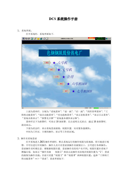
DCS系统操作手册1、系统界面。
打开系统时,系统界面如下:上部为菜单栏,分别为“系统菜单”,“前一副”,“后一副”,“图形管理菜单”,“工程师功能菜单”,“综合功能菜单”,“历史趋势菜单”,“显示表格菜单”,“显示日志菜单”,“系统名称显示”,“报警光字牌”“系统基本属性显示框”。
菜单栏以下为报警栏,可显示10条报警,以点说明方式显示,超过10条报警时,滚动显示。
下部为状态栏,显示系统登录级别、权限位置,还有服务器属性。
中间为工作区,主要的操作、显示等工作的区域。
2、操作员系统登录打开系统进入DCS操作界面时,默认系统运行的操作权限为监视级,即只能进行观察,不可以进行任何操作,操作人员只有登录到操作员级别以上,方可进行各种操作。
登录操作员时要注意,要根据权限位置,登录操作员的用户名不同。
权限位置在系统下侧偏右端,如显示“操作员级权限1”则表示此操作员站现在权限位置为“1”,登录的级别为操作员级。
目前只设置“权限1”和“权限0”两种权限位置。
选择“工程师工程功能菜单”—>“登录”,登录界面如下:登录操作员时:,权限1对应的操作员登录的用户名为ops,没有密码。
权限0对应的操作员登录的用户名为ops0,没有密码。
登录到操作员后,可对系统进行基本操作,添加趋势,查看报警等。
3、趋势查询操作画面上有各种数据显示点,右键单击该点,选择点趋势,可查看该点的趋势画面。
注意:趋势画面是记录可以查看前推最近一次下装服务器到当前时间的点趋势。
点趋势画面如下:上侧,分别显示该点的点名,时间间隔。
时间间隔可以输入从1~60的整数,单位是秒,时间间隔是趋势曲线变化的时间率,即输入5秒,曲线5秒钟变化一次。
趋势曲线的状态可分为“跟踪”和“历史”两种状态,选择跟踪,曲线便根据时间间隔和实际数据变化而实时更新,选择历史则曲线不再变化,而点趋势画面下侧的“前推”和“后推”按钮可用,每推一次即翻一页。
趋势显示的方式分为“曲线”和“数字”两种,选择数字,则点的趋势以数据方式显示。
OVATION组态手册范本精选全文

可编辑修改精选全文完整版OVATION组态手册范本托电一期2X 600MV工程DCS系统组态说明手册(部参考)2002年6月14日目录一、OVATION态常用命令二、AUTOCAD明三、I/O BUILDE建立说明四、系统组态中间点标签名定义五、画面组态说明第一部分OVATIO组态常用命令1 UNIX命令2如何把数据库的容转换成可下载到SERVER的文本文件2.1在OVATIO系统中加入一点,将该点的各项填好,并将其输出,生成一个文本文件做为模板。
注:模拟量和数字量的标准WORID入文件格式见目录:“工程组态文件导入\Sampie目录下的文件:模拟量:aiosample4-20ma.doc对应查询中的“A导入4-20MA)aiosampieAO.doc aiosampleCJ.docaiosampleQTA.doc其它,一般指CT)aiosampleRTD.docaiosampleTC.doc数字量diosampleGEN.doc 与查询中的DIO_DETA对应)2.2在WOR中打开模板文件,在“工具”中选择“合并”2.3 在“合并帮助器”中的第1项“主文档”下选择“套用信函”,然后选择“活动窗口”;选择第2项,在“数据源”下选择“打开数据源”,然后选择数据库中相应的表或查询;最后关闭“合并服务興”器”。
如果WOR文件已经和一个数据源,可以直接进入第2项,选择“数据源”中的“打开数据源”重新建立一个数据源。
如果被查询的容被修改,那么应将查询文件存盘后,在WOF文件中对数据源重新进行。
2.4 在“插入合并域”中选择合适的域来替换模板文件中相应的容。
2.5 在图标中选择“合并到新文档”。
2.6 最后另存为纯文本文档。
3 如何把生成的纯文本文档拷贝到SERVE中3.1压缩纯文本文件,并拷贝到软盘上。
如命名为Dzip。
3.2用cd usr/wdpf/caibo命令进入预先建立的目录(如caibo)。
3.3将软盘插入,用df -k指令检查软盘是否挂上,如未挂上,用volcheck 命令将其挂上。
Ovation中文说明书
网络标准
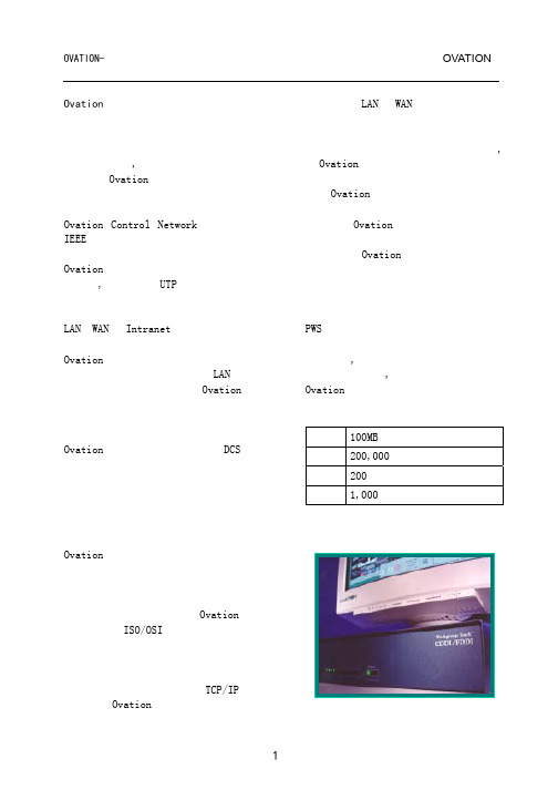
Ovation 能够把控制机制和信息整体结 合起来,是实现投资目标的有效途径。 它能允许最终用户使用最好的方法来组 织他们的信息集合,而不用考虑协议、 网络管理和操作系统等等。Ovation 网 络软件使用 ISO/OSI 可以在任何一个标 准物理网络层中通讯,具有所有网络的 特性:冗余、同步、确定和令牌传输。 当在与以太网、快速以太网、令牌环或 其它拓扑结构相连时它使用 TCP/IP 协 议。因为 Ovation 系统在控制系统网络
离
· 14 位分辨率 · 提供调节过的隔离电源(使用二维
变压器技术)
· 在线初始认定,使用 EEPROM 存储整
定常数 模拟量输入模件:
· 8 路信号输入 · 不 同 输 入 等 级 组 态 : +/-20mV ,
+/-50mV,+/-100mV,0-1V,0-5V, 0-10V, 4-20 mA, 1-5VDC
清单中清除后改变报警的状态,它将自 动恢复到不能再次被释放的状态。 冗余 Ovation 控制器的设计是能够提供不同 关键设备的冗余要求,包括:
· 网络接口 · 功能处理器、内存和网络控制器 · 处理器电源 · I/O 电源 · 输入电源 · I/O 电源 · 输助电源 · 远程 I/O 通讯媒介
全冗余的控制器能配备:
摘要 Ovation 控制器提供对多处应用程序的 支持,具有强大的适应性、灵活性和价 格优势和控制能力。因为采用了工业标 准的硬件和软件平台,控制器的技术可 以同步于一个工厂的生命周期内需要升 级。Ovation 用户可以简单到只更换商 用的 CPU 来升级控制器。安装第三方的 设备同样快捷。
DCS系统操作手册

DCS系统操作手册1、系统界面。
打开系统时,系统界面如下:上部为菜单栏,分别为“系统菜单”,“前一副”,“后一副”,“图形管理菜单”,“工程师功能菜单”,“综合功能菜单”,“历史趋势菜单”,“显示表格菜单”,“显示日志菜单”,“系统名称显示”,“报警光字牌”“系统基本属性显示框”。
菜单栏以下为报警栏,可显示10条报警,以点说明方式显示,超过10条报警时,滚动显示。
下部为状态栏,显示系统登录级别、权限位置,还有服务器属性。
中间为工作区,主要的操作、显示等工作的区域。
2、操作员系统登录打开系统进入DCS操作界面时,默认系统运行的操作权限为监视级,即只能进行观察,不可以进行任何操作,操作人员只有登录到操作员级别以上,方可进行各种操作。
登录操作员时要注意,要根据权限位置,登录操作员的用户名不同。
权限位置在系统下侧偏右端,如显示“操作员级权限1”则表示此操作员站现在权限位置为“1”,登录的级别为操作员级。
目前只设置“权限1”和“权限0”两种权限位置。
选择“工程师工程功能菜单”—>“登录”,登录界面如下:登录操作员时:,权限1对应的操作员登录的用户名为ops,没有密码。
权限0对应的操作员登录的用户名为ops0,没有密码。
登录到操作员后,可对系统进行基本操作,添加趋势,查看报警等。
3、趋势查询操作画面上有各种数据显示点,右键单击该点,选择点趋势,可查看该点的趋势画面。
注意:趋势画面是记录可以查看前推最近一次下装服务器到当前时间的点趋势。
点趋势画面如下:上侧,分别显示该点的点名,时间间隔。
时间间隔可以输入从1~60的整数,单位是秒,时间间隔是趋势曲线变化的时间率,即输入5秒,曲线5秒钟变化一次。
趋势曲线的状态可分为“跟踪”和“历史”两种状态,选择跟踪,曲线便根据时间间隔和实际数据变化而实时更新,选择历史则曲线不再变化,而点趋势画面下侧的“前推”和“后推”按钮可用,每推一次即翻一页。
趋势显示的方式分为“曲线”和“数字”两种,选择数字,则点的趋势以数据方式显示。
艾默生dcs操作规程
艾默生dcs操作规程艾默生DCS(Distributed Control System)是一种用于工控系统的控制系统,它通过分布在各个控制节点上的智能终端进行数据采集和控制操作,具有高性能、高可靠性和高可扩展性的特点。
为了保证DCS系统的正常运行和安全性,需要制定一套操作规程。
以下是艾默生DCS操作规程的相关内容。
一、操作前准备1. 操作人员应熟悉DCS系统的基本结构和功能,了解主要控制节点的位置和功能。
2. 了解待操作的设备和系统的性能和特点,熟悉其操作和维护手册。
3. 清理操作现场,确保安全设施齐全,设备无异常。
二、开机操作1. 操作人员应按照DCS系统的启动顺序逐一启动各个控制节点。
2. 检查各个控制节点的连接状态和通信功能是否正常,确保系统网络畅通。
3. 检查各类传感器和执行器的状态是否正常,如有异常及时报修。
三、参数设定与监控1. 根据生产工艺需求,设置各个控制节点的参数,包括温度、压力、流量等。
2. 通过DCS系统监控界面查看各个参数的实时数值,如发现异常情况进行相应的处理。
3. 根据实时数据进行判断和估测,及时进行调整以保证系统的稳定运行。
四、报警处理1. 当DCS系统中出现报警时,操作人员应迅速响应,查看报警原因。
2. 根据报警信息,判断是否需要采取应急措施,如停机、降负荷等。
3. 在处理完报警后,应及时记录报警信息和处理过程,并对相应设备进行检修或维护。
五、应急操作1. 当DCS系统出现突发故障或其他异常情况时,操作人员应按照应急预案进行处理。
2. 保持冷静,迅速定位故障原因,并采取合理措施进行修复或恢复。
3. 在应急操作结束后,应进行故障分析,并及时更新操作记录和预案,以便今后参考。
六、操作记录和交接1. 操作人员应根据操作情况及时记录操作日志,包括开机时间、参数设定、报警处理等。
2. 在交接时,应向接班人员详细说明当班操作情况,提醒注意事项和需要关注的问题。
3. 注意保密,操作记录和交接内容应只限于授权人员查阅。
艾默生DCS_OVATION系统手册

OVATION系统硬件培训手册(Solaris操作系统)Rev.1上海西屋控制系统有限公司(Aug.2005)OVATION系统 目录Ovation 系统硬件第一章 Ovation分散控制系统概述1.1 系统概述 ……………………………………………………………1-11.2 典型的Ovation系统结构 ……………………………………………1-31.3 Ovation系统诊断 ……………………………………………………1-41.4 参考手册 ……………………………………………………………1-7第二章 Ovation系统网络2.1 系统的组成 ……………………………………………………………2-12.2 网络的结构形式 …………………………………………………... 2-12.3 单网网络星形拓扑结构………………………………………………….. 2-32.4 多网网络 …………………………………………………………... 2-42.5 网络设备的功能 ……………………………………………………2-42.5.1 快速以太网的一般概念 ………………………………….. 2-42.5.2 集线器(Hub) ……………………………………………2-52.5.3 交换机(Switch) …………………………………………... 2-52.6 Ovation网络地址 ……………………………………………………. 2-62.7 网络中的数据流 ……………………………………………………. 2-7第三章 Ovation控制器3.1 控制器 …………………………………………………………3-108/16/05 1目录 OVATION系统3.2 控制器硬件的组成 ………………………………………………… 3-23.1.1 控制器的面板指示 …………………………………………. 3-33.1.2 控制器的标准功能 ………………………………………… 3-43.1.3 控制器的数据流程 …………………………………………. 3-53.1.4 控制器的故障切换 …………………………………………. 3-6 3.2 控制器的供电系统 ……………………………………………………3-63.2.1 供电系统 ……………………………………………………3-63.2.2 电源分配板(PDM) …………………………………………. 3-83.2.3 控制器的接地系统 ……………………………………………3-93.2.4 系统上电注意事项 ……………………………………………3-10 3.3 I/O子系统 ………………………………………………………….. 3-153.3.1 I/O子系统的结构形式 ……………………….……………….. 3-153.3.2 I/O基座结构 ……………………………………………………3-183.3.3 模块的分类及安装 …………………………………………. 3-193.3.3.1 模块的构成 …………………………………3-193.3.3.2 模件的安装 …………………………………3-193.3.3.3 模件的面板指示 …………………………3-193.3.4 机柜类型及卡件安装 ……………………………..…………. 3-203.3.4.1 控制器机柜 …………………………………3-203.3.4.2 控制机柜的命名 …………………………3-213.3.4.3 各机柜间的连接 …………………………3-213.3.5 I/O通讯方式 ……………………………………………………3-223.3.5.1 本地I/O连接方式 …………………………3-223.3.5.2 远程I/O子系统 …………………………3-24第四章 常用I/O卡件介绍4.1 模拟量输入卡(13位) ……………………………………………………4-1 4.2 模拟量输入卡(14位) ……………………………………………………4-6 4.3 高速模拟量输入及热电偶卡 ……………………………………………4-1308/16/05 2OVATION系统 目录4.4 模拟量输出卡 ………………………………………………………………4-294.5 混合型触点输入卡 ………………………………………………………4-324.6 触点输入卡 ………………………………………………………………4-364.7 触点输出卡 ………………………………………………………………4-404.8 4通道热电阻RTD输入卡 ………………………………………………4-464.9 8通道热电阻RTD输入卡 ………………………………………………4-564.10 HART模拟量输入卡 ………………………………………………………4-604.11 HART模拟量输出卡 ………………………………………………………4-644.12 紧凑型顺序事件输入卡(SOE) ………………………………………………4-684.13 链接控制卡(Link Control Card) ………………………………………4-734.14脉冲计数卡 …………………………………………………………………4-754.15阀位卡 …………………………………………………………………4-824.16测速卡 …………………………………………………………………4-854.17回路接口卡 …………………………………………………………………4-87第五章 工作站5.1 工作站类型及硬件组成 ………………………………………………. 5-25.1.1 工作站的类型 ……………………………………………………….. 5-25.1.2 工作站的硬件组成 ……………………………………………….. 5-35.2 操作员站 ……………………………………………………………….. 5-35.2.1 操作员站的特点 …………………………………………….. 5-45.2.2 操作员站的功能 …………………………………………….. 5-45.3 ENG工程师站 ………………………………………………………………. 5-105.3.1 工程师站的特点 …………………………………………….. 5-105.3.2 工程师站的功能 …………………………………………….. 5-115.4 HSR 历史站 ………………………………………………………………5-135.4.1 历史站的特点 ………………………………………………………5-1308/16/05 3目录 OVATION系统5.4.2 历史站的功能 ……………………………………………………5-15 5.5 Ovation(LOG)记录服务器 ……………………………………………5-175.5.1 LOG服务器特点 ……………………………………………5-175.5.2 基本LOG服务器软件包 ……………………………………5-17 5.6 打印机 ………………………………………………………………5-1908/16/05 4OVATION系统系统概述第一章 OVATION 分散控制系统概述1.1 系统概述Ovation系统是集过程控制及企业管理信息技术为一体的融合了当今世界最先进的计算机与通讯技术于一身的典范。
浅谈艾默生DCS系统OVATION3.51接地
浅谈艾默生 DCS 系统 OVATI ON3. 51接地摘要:艾默生新版OVATION3.51DCS分散控制系统对接地的要求非常严格。
接地设计及安装的好坏直接影响到系统运行的质量,因此工程技术人员还必须重视DCS接地问题。
DCS系统合理、准确及可靠接地,是保证电厂机组DCS安全稳定可靠运行的必要条件,是系统网络通信畅通无阻的重要前提。
正确的接地不仅能抑制外部来的干扰,还能减少设备对外部的干扰影响。
下面就从几个方面来谈谈艾默生新版DCS控制系统 OVATION3.51接地问题。
关键词:分散控制系统;接地;抗干扰1DCS接地分类通常DCS控制系统需要保护地和工作地两种接地,其中工作地包括逻辑地、屏蔽地等。
保护地(CG):DCS系统所有设备都应接保护地,包括端子柜、打印机、现场控制站机柜、操作员机柜等,其目的是为了防止设备外壳的静电荷积累、避免造成人身伤害。
保护地应接至厂区电气专业接地网,接地电阻小于4Ω。
逻辑地(PG):又称主机电源地、机器逻辑地,需要接入公共接地极,是计算机内部的逻辑电平负端公共地,也是+5V等的电源输出地。
屏蔽地(AG):也叫模拟地。
由于它能够有效屏蔽掉现场信号传输时受到的干扰,具有大大提高信号精度的作用。
DCS系统中信号电缆的屏蔽层应做屏蔽接地。
线缆屏蔽层必须一端接地,防止形成闭合回路干扰。
铠装电缆的金属铠不应作为屏蔽保护接地,必须是铜丝网或镀铝屏蔽层接地。
接入公共接地极。
2DCS接地方式通常DCS系统的接地方式有以下三种:①设DCS专用接地网,经接地线,再接至电气接地网;②设DCS系统专用独立的接地网;③利用电气接地网作为DCS接地网,即与电气接地网共地。
艾默生公司的 OVATION3.51系统,为保证机组DCS的安全运行,OVATION系统要求配置独立的DCS接地地桩,不能与其它系统共用。
根据电厂实际情况要求DCS应有单独安装的接地网,DCS接地系统应由地下主接地网及地上接地支线电缆组成,并保证接地电阻达到DCS厂家规定设计值。
艾默生空气压缩机手册说明书
PISTON COMPRESSOR MANUAL REV022621Contents Safety Information 2-3 Breathable Air 3Pressurized Components 3Personal Protective Equipment 3 Nomenclature 4 Features and Extras 5-7 Pump Riser 5Belt Tensioner 5Continuous Run 6Automatic Tank Drain 7 Installation 8-16 Area 8Lifting and Movement 9General Lifting 9Anchoring 10Electrical 11-14 Piping 15-16 Pre-use Inspection 17 Operation 18Pump Times 18 Maintenance 19-20 Maintenance Schedule 19-20 Oil Change/Selection 20Oil Disposal 20 FAQ and Troubleshooting 21 Warranty Information 22-24SAFTEY INFORMATIONThis manual contains very important information to know and understand. This is to provide for SAFTEY and to PREVENT EQUIPMENT PROBLEMS. To help understand this information, observe the following:DANGER:Danger indicates and imminently hazardous situation which, if not avoided, will result in death or serious injury.WARNING: Warning indicates a potentially hazardous situation which if not avoided, could result in death or serious injury.CAUTION:Caution indicates a potentially hazardous situation which, if not avoided, may result in minor or moderate injury.NOTICE:Notice indicates important information, that if not followed, may cause damage to equipment.CALIFORNIA PROPOSITION 65WARNING:This product or its power cord may contain chemicals known to the state of California to cause cancer and birth defects or other reproductive harm. Wash hands after handling.1.Allow only trained, authorized persons who have read and understood these operating instructions to use thisequipment. Failure to follow the instructions, procedures and safety precautions in this manual can result inaccidents and injuries.2.NEVER start or operate the compressor under unsafe conditions. Tag the compressor, disconnect,and lock out all power to it to prevent accidental start-up until the condition is corrected.3.Install, use, and operate the compressor only in full compliance with all pertinent OSHAregulations and all applicable Federal, State & Local codes, standards, and regulations.4.NEVER modify the compressor and/or controls in any way.5.Keep a first aid kit in a convenient place. Seek medical assistance promptly in case of injury. Avoidinfection by caring for any small cuts and burns promptly.BREATHABLE AIR1.NEVER use air from this compressor for breathable air except in full compliance with OSHA Standards 29CFR 1910 and any other Federal, State or Local codes or regulations.2.DO NOT use airline anti-icer systems in air lines supplying respirators or other equipment used to producebreathable air. DO NOT discharge air from these systems in unventilated or other confined areas.Pressurized ComponentsThis equipment is supplied with an ASME designed and rated pressure vesselprotected by an ASME rated relief valve. Pull the ring before each use toensure the valve is functional. DO NOTattempt to open the valve while themachine is under pressure. See figure on the right.Personal Protective EquipmentBe sure all Be sure all operators and others around the compressor and its controls comply with all applicable OSHA, Federal, State and Local regulations, codes, and standards relating to personal protective equipment. This includes respiratory protective equipment, protection for the extremities, protective clothing, protective shields and barriers, electrical protective equipment, and personal hearing protective equipment.NomenclatureFeatures and ExtrasCompressors come in many shapes and sizes. Our units have several features that may or may not be present on your unit. These features may be purchased after the fact in kit form. This guide will explain the use and benefit of these features.Pump RiserBelt TensionerContinuous RunContinuous run allows the pump to turn continuously, hence the name. In this mode the unit pumps up to 140 PSI and then the valves are held close. This allows the pump to enter a free spin state where the unit is pulling in cold air and the simply cycling it back to atmosphere. This has several benefits:1.The pump is cooled during the free spin state since it has no pump load on it.2.Increased recovery time since the function cycles between 100 and 140 PSI; which is the optimal CFMwindow for the unit.3.Wear on your motor is decreased (especially single-phase units) as the unit is already in motion and will notneed the large amp draw to overcome zero movement and fight tank compression.4.Continuous run is best used in applications where CFM cannot be lost. Some examples of this are: mediablasting, painting, and prolonged grinding or resurfacing.Auto DrainAuto drains are preset timer valves that allow tank moisture to be vented as long as they are powered. The enemy of every compressor/air system is moisture. The auto drain removes some of the hassle of this by allowing the user to set a timer and walk away from the unit with the piece of mind that their system is protected.1. The drain works off a conventional 120V outlet.2. Timer has built in intervals that can be customized to the user need.3. Has a manual shut off for service and maintenance.4. The drain filter MUST be cleaned weekly to prevent drain blockage.5.Drain time knob, marked as ON:SEC , corresponds to how long the drain will run for when it comes on. This is listed in seconds.6. Drain interval knob, marked as OFF: MIN , corresponds to how long between cycles. Or how long the drainwill be OFF before it comes on again.7. The drain attaches to a ½” NPT female connection.8. The vent can blow to atmosphere; however, the drain is supplied with a drain silencer system which can beused to muffle the sound of the unit draining. This screws into the atmospheric vent location, however, it is not necessary for operation.9.A drain system can also be equipped by the user to allow moisture to drain to a separate location.10. The drain is also equipped with a test button to check function.InstallationArea1.Install compressor in a clean, dry, and well-lit area. Be sure installation area can maintain a temperaturerange between 35˚ - 110˚F.2.Allow sufficient space around the compressor for maintenance access and adequate airflow. Mount unit withthe belt guard (pulley and flywheel) side to the wall and leave a minimum of 15 inches of clearance.3.If acid is used in operating environment or air is dust laden, pipe intake to outside fresh air. Increase pipe sizeby 1/8”’ for every 20ft of run. Be sure to install a protective hood at the outside air intake location to prevent debris and foreign objects from blocking the intake pipe.4.In operating environments where excessive water, oil, dirt, acid, or alkaline fumes are present, a TEFC (totallyenclosed, fan cooled) motor is highly recommended. Check nameplates for motor type.5.Insulate cold water or tother low temperature pipes that pass overhead to avoid condensation dripping onthe compressor.6.In environments where fine dust is common such as granite, marble, or concrete plants the unit must beinstalled in a separate room with its own dedicated ventilation system.7.The unit can be stored outside under the following guidelines: It must be in a covered area out of extremeweather with no ability for moisture to get to the unit, it is also highly recommended that the unit is out of direct sunlight as it can fade and/or damage the coating on the unit. Direct sunlight may also interfere with safety decals on the unit.8.If the unit is in an enclosed space it requires proper ventilation as the ambient air temp where thecompressor is located CANNOT exceed 115 degrees F.e shims to level the compressor if installation area is not flat. This will help prevent excessive vibration andpremature pump wear.Lifting and Movement/Forklift1. Make sure lift operator stays aware while moving the compressor.2. Be sure to uncrate the compressor prior to movement. This will allow a visual reference for the balance ofthe unit.3. Be sure the load is secure and well balanced before moving the compressor.4. Make sure the forks are fully engaged and level prior to lifting or moving the unit.5. Keep the unit/load as low as possible while moving and refrain from quick changes in direction.6. For all other forklift safety standards/regulations please reference OSHA 1910.178- Powered industrialtrucks.General Lifting Information1. Carefully inspect all lifting equipment and ensure it is in good condition. Rated capacity of lifting equipmentmust exceed compressor weight. NEVER lift with under sized or damaged equipment.2. If using lifting equipment, ensure all lifting points are in good condition and tighten any loose nuts or boltsbefore lifting.3. A sling MUST be used when moving the compressor with a helicopter or other airborne equipment. Be sureto follow OSHA standards 1910 subpart N.4. Use guide ropes or equivalent to prevent twisting or swinging of the compressor while it is in the air andNEVER attempt to lift the unit in high winds. Keep compressor as low to the ground as possible.5. Keep all persons away from the compressor when it is lifted. DO NOT allow persons under the compressorwhile it is being lifted.6. DO NOT use bolts or other hooks on individual components to move the compressor.7. When moving and or placing the compressor ensure it is on/across a surface that can hold the combinedweight of the compressor and the loading equipment.AnchoringTo ensure proper and safe operation of the compressor the unit is required to be anchored to a flat, smooth,concrete floor. Compressors are also required to be on ¼ inch (6.35mm) MAXIMUM thick rubber anti-vibration pads.Recommended anchor Bolt specifications: wedge anchors; 3/8 in width by 3.5 in length.How to Anchor the Compressor1. Make sure the compressor is in the desired location and the anti-vibration pads are under the feet of thecompressor.2. Using the holes in the feet as guides, drill the holes for the anchor bolts through the vibration pads and intothe concrete.3. Thoroughly clean each hole.4. Put the Washer and Nut into place, make sure the top of the Nut is flush with the top of the anchor bolt, theninsert the anchor bolt into the hole.5. Hammer or mallet the anchor bolt down into the hole.6. Tighten each nut clockwise , DO NOTover tighten. DO NOTuse an impact to tighten the anchors.Electrical Safety1. Follow all NEC and local codes for electrical wiring. Allow only authorized service personnel or certifiedelectricians to install electrical components.2. Put unit on a dedicated circuit and make sure no other electrical equipment is wired into it. Failure to wireunit on an independent circuit can cause circuit overload and/or imbalance in motor phasing. Install proper No Fuse Breaker (NFB) according to the chart listed below. You may also reference NEC and local codes for additional support.3. Ensure incoming service has adequate ampere rating.4. Do not used mixed wire sizes when wiring the unit.5. The unit must be properly grounded. DO NOT connect ground to air or cooling lines.Wiring the Compressor1. Voltage should not vary more than 12% to ensure proper operation of the compressor.2. Wire size and breaker requirements for single phase units:**3. Wire size and breaker requirements for 3 phase units:**Wire size distances are from unit to the panel where the breaker is housed.**CAUTION: Under sizing wires and/or breakers can cause damage to the unit, possible injury to personnel, and void your warranty.4. Single phase unit, NO magnetic starter:5.Single phase unit WITH magnetic starter:6.Three phase unit wire diagram (Three phase will ALWAYS have magnetic starter):7.During initial start up of 3 phase unit, pay attention to flywheel rotation. When facing the front of thecompressor (Pressure switch/pressure gauge side) rotation should be clockwise. If rotation iscounterclockwise, switch incoming power leads at 3L2 and 5L3 (ensure power is off at the breaker before attempting any changes).Piping (Safety steps)1.Install appropriate flow-limiting valves as necessary according to pipe size(s) used and run lengths. This willreduce pressure in case of hose failure, per OSHA Standard 29 CFR 1926.302(b)(7).2.Flow-limiting valve are listed by pipe size and rated CFM. Select appropriate valves according tomanufacturer’s recommendations.e a flexible connector between compressor tank and dryer/piping system to minimize noise, vibration,pump wear, and to prevent damage to the unit or piping system.4.Install ASME code safety valves and ensure piping system is equipped with adequate condensate drains.5.Minimum pipe size for compressed air lines: (Pipe sizes are shown in inches)PISTON COMPRESSOR MANUAL REV0226216.Air systems should be checked daily for leaks. This helps to prevent unnecessary load on the compressor andhelps increase energy savings.7.Examples of air systems:Closed loop system. Install tee fitting in piping from air to minimize pressuredrop and to allow air flow in two directions.Air DropAir Drop: Install tee fitting withbranch to top to minimizecondensation.From CompressorElevation View8.Make sure any tube, pipe, fitting, or hose connected to the unit can withstand operating temperatures andretain pressure.9.Never use reducers in discharge piping. Keep all piping and fittings the same size in the piping system.WARNING: Never use plastic (PVC) pipe for compressed air. Serious injury ordeath could result. Piping MUST have a pressure rating of 200 PSI or greater.Pre-Use Inspection1. The unit is shipped with pump break-in oil and should be ready to operate. Be sure to check for proper oil levelbefore running the compressor. Break in oil should be change after 100 Hours of operation (active pumping time). See maintenance section for more information on oil changes and frequency.2. Check for proper belt tension. There should be ½ inch of belt slack/deflection. Refer to maintenance section ifadjustment is necessary.3. Inspect belts for frays or unit for an excess buildup of black rubber dust indicating belt wear.4. Check proper operation of all pop off safety valves on unit. Pull rings on valves to ensure they move and are freeof any obstructions. DO NOT pull the safety valve on the tank if there is air in the tank!5. Inspect all air lines/piping for proper for secure fit and corrosion or line degradation. DO NOT operate thecompressor with damaged lines. DO NOT use damaged or cracked air lines as a rupture could result in damage/injury to personnel or property.6. WITH UNIT LOCKED OUT (power off at source i,e. the electrical panel/disconnect) ensure all electrical wiring,including all terminals, are in good condition and are free of buildup, fraying, cracks or discoloration replace as needed. Check tightness of bolts securing wiring in place.7. Ensure unit is secured in place and has not shifted. Verify anchor bolts are in place and are in good condition. 8. Remove any loose items from around/on compressor to avoid damage to the unit. Examples would be looseclothing items, rags, papers, bottles, or any item that may have been placed on the unit. 9. Check unit for any oil leaks. If leaks are found contact manufacturer for further instructions. 10. Unit should NEVER be operated without the belt guard in place.11. Inspect Flywheel for cracks or missing fins. NEVER operate a unit with a damaged flywheel; serious injury ordeath could result. If you suspect your flywheel may have been damaged, contact technical assistance and DO NOT allow the machine to be operated.Ensure all personnel that work around or operate the compressor have read this manual and are well versed in the operation of this machinery. NEVER allow untrained personnel to operate this unit.1. Once the inspection is completed, open your discharge port (outlet ball valve). This should already be connectedto your shop airline system.2. Ensure all personnel are clear of the compressor and aware that it is being started.3. Turn the selector on your pressure switch to AUTO. This will start your compressor and allow it to fill. The tankwill fill to 175 PSI, and unless otherwise noted, will shut off. The unit will begin pumping again once the tank is drained down to approximately 135 PSI. ***This may vary based on features, if your unit is equipped withCONTINOUS RUN , the unit may perform differently then specified in this step. (Check the FEATURES section for more information)4. Oil pressure on start up will vary due to ambient temperatures but should not exceed 100 PSI. Once the unit isallowed to run a few cycles and come to optimal operating temperature, oil pressure should stabilize at 20-35 PSI. If the oil pressure remains high or drops too low, it can be adjusted as follows:Pump Up Time (General)Compressor maintenance must be performed as described in the maintenance schedule, failure to do may lead to compressor/component breakdown and void compressor warranty.Maintenance ScheduleThe table below is a generalized maintenance schedule based on the normal usage of a compressor. Your specific needs may vary based on operating environment and duty.Frequency of these changes are a generalization and may be subject to change based on compressor environment, hours, and application.Oil ChoiceIt is strongly advised to use only Airbase Industries piston compressor oil. Check with your warranty/extended warranty guidelines to verify oil selection and use. Oil used in the compressor must fall under the following criteria: synthetic, SAE grade 30, non-detergent, piston compressor oil.Oil DisposalCompressor oil is not trash and MUST NOT be disposed of in regular trash or discarded into the environment. You MUST dispose of waste oil from your unit per all applicable federal, state, and/or local codes. Failure to do so may damaged the environment and subject yourself and/or your business to fines and legal issues.TroubleshootingSome unit issues can be fixed simply by verifying the following guide. It is advised to go through the guide prior to calling technical support to help expedite the assistance process.Warranty Statement•Standard Warranty: That each compressor unit is free from defects in material, workmanship, and parts for1 year from the date of delivery. This Standard Warranty includes 1 year of warranty labor from anauthorized technician. Manufacturer is not responsible for downtime during warranty service. If downtime is necessary, it is at the owner’s discretion, obligation, and expense, to h ave a redundant compressor.• Parts shipped for warranty repairs shall only include ground freight charges for the first 90 days of the warranty period, thereafter owner is responsible for all freight charges of parts shipped for warranty. Any and all expre ss shipping charges of warranty parts would be at the owner’s expense. Standard technicalassistance is provided at no charge during and after the standard warranty period.*Standard warranty has no obligation to maintain warranty status, warranty will expire one year from date of delivery. Please see available options below to extend your warranty.•Extended Warranty: Manufacturer will extend your standard 1-year warranty to full 5 years when you opt to register for the extended warranty plan that includes using our SMART OIL™ and following all routinemaintenance set forth. Parts shipped for warranty repairs shall only include ground freight charges for the first90 days of the warranty period, thereafter owner is responsible for all freight charges of parts shipped forwarranty. Any and all express shipping charges of warranty parts would be at the owner’s expense. Standard technical assistance is provided at no charge during and after the standard warranty period.Required maintenance schedule to maintain warranty status.➢All units are shipped with break-in oil and must be changed no less than 70 hours to i nsure gasket seating.➢After the 100 hours of break-in, you must change the oil.➢Thereafter Oil Should be changed every 6 months or 1000 hours whichever occurs first.➢Always maintain proper oil level in unit. If the unit runs out of oil due to neglect the warranty w ill be void.➢Use only manufacturer approved oils in your compressor, or your warranty is void.➢All stock orders by vendor/purchaser are required to purchase two service kits at time of purchase per unit.➢All stocking orders will have a 6-month grace period for warranty registration. After that time the unit must be registered, or warranty may be void.**Extended Limited Lifetime Pump Warranty With participation in our SMART OIL™ extended auto shipprogram will extend your warranty plan to **Limited Lifetime Warranty on the pressure lubricated pump.All other non-wear and tear components to 10 years. SMART OIL™ not only extends the life of yourcompressor pump, it also can reduce operating noise levels and can create further energy savings.Warranty repair parts under the Limited Lifetime warranty will not include any shipping charges beyondthe Standard Warranty, therefore owner is responsible for all freight charges for warranty parts. This planincludes our advanced technical air support. Smart Tech Support provides you with the highest level oftechnical support. Smart Tech support is an interactive support team available to you at your fingertips byjust downloading a free app. The app provides free remote meetings, interactive touch display, real livepersonal to assist.Limited Lifetime Warranty is not prorated and has no hour limits.**Limited Lifetime Warranty, non-prorated, no hour limits. In the case the product has been discontinuedat any point the Limited lifetime Pump warranty will last five years past the discontinued date. Warrantorhas discretion to substitute parts with current model for the five-year duration.*In order to maintain Limited Lifetime Warranty status, the owner must adhere to and purchase the required maintenance items as scheduled below utilizing our Smart Whisper Blue Auto Ship program:Required maintenance schedule to maintain warranty status.➢All units are shipped with break-in oil and must be changed no less than 70 hours to i nsure gasket seating.➢After the 100 hours of break-in, you must change the oil.➢Thereafter Oil Should be changed every 6 months or 1000 hours whichever occurs first using only our Smart Whisper Blue Oil➢Always maintain proper oil level in unit. If the unit runs out of oil due to neglect the warranty w ill be void.➢Use only Smart Whisper Blue Oil and filters purchased from original manufacturer in y our compressor, or your warranty will be voided.➢Must be an active member of auto ship program.➢All stock orders by vendor/purchaser are required to purchase two service kits at time of purchase per unit.➢All stocking orders will have a 6-month grace period for warranty registration. After that time, the unit must be registered, or warranty may be void.•Warranty shall not apply, and manufacturer shall not be responsible nor liable for:➢Routine service such as oil changes, filter replacements, gasket tightening t o correct oil seepage or drive belt tightening and valve cleaning and are not covered under warranty.➢Consequential damages such as but not limited to cost of loss of business, product damage, or down time.➢Acts of nature, over abuse, malicious destruction, improper maintenance, undersized equipment➢In the case the product has been discontinued at any point the *Limited lifetime warranty w ill last five years past the discontinue date. Manufacturer has discretion to substitute parts with currentmodel for the five-year duration.➢Deviation from operating instructions or specifications➢Labor charges for repairs or maintenance made by person(s) other than an authorized, a pproved service technician or any labor after the 1-year Standard Warranty expires.➢Normal wear and tear parts included but not limited to valves (intake/suction, check, b lowdown, thermo, pop off, unloader), and ball valves. Belts, shaft seals, load/unloader solenoids, sensors(temperature or pressure), Electrical contractors and relays, and any parts with a routinemaintenance scheduleWarranty shall be voided under the following conditions: Exposing electrical components to rain or water or installing the unit in a hostile environment such as acid vapors or any caustic or abrasive matter that may be ingested into the pump or installing the unit in an enclosed area where lack of cooling ventilation is present, such as in boiler or equipment rooms where the ambient air exceeds 100F.Further exclusions include failure to fully and completely follow the guidelines set forth in the manual. Of specific note is environments where fine dust is common, such as granite, marble or concrete plants, the compressor MUST be installed in a separate area with its own dedicated ventilation. FAILURE TO PROVIDE THIS DUST FREE OPERATING AREA VOIDS THE WARRANTY.Parts used for warranty purposes must be supplied by original manufacturer. Warranty work should be performed only by an approved technician. If any maintenance (other than routine maintenance) is performed by a non-approved Technician, written pre-approval must be obtained from manufacturer, to prevent voiding this warranty. Failure to fully comply with this warranty and fully comply with the manual instructions will void this warranty.The oil purchase and maintenance program are effective as of Jan.2020。
dcs系统操作说明
1
冗余CONTROLNET控制网
1
冗余 控制器
NET OK NET OK NET
1
1
I/O机架
4、5、7、8磨机系统的 变频器频率检测设定、 电子秤检测设定信号、 磨机电流、大瓦温度信 号及运行、故障信号,
管道化系统的流量检 测、矿浆密度、槽液 位、电机电流检测及 泵、电机、电子秤的 启动停止信号
1、2、3、6磨机系统的 变频器频率检测设定、 电子秤检测设定信号、 磨机电流、大瓦温度信 号及运行、故障信号,
高压溶出系统的流量检 测、矿浆密度、槽液位 、电机电流检测及泵、 电机、电子秤的启动停 止信号 .
中国铝业股份有限公司郑州研究院
第一部分 DCS系统综述
3、PlantScape系统概述 PlantScape TM作为Honeywell公司90年代最新推出的开放型控制系统, 以Windows NT 为操作系统,包含了最新设计的混合型控制器(Hybrid Controller)和实时控制网 (ControlNet) ,以及高级的工程工具和应用 软 件包,成为新一代系统的标准。 3.1 PlantScape TM主要采用以下新的技术: --Microsoft Windows NT 服务器,具有动态数据高速缓存、报警、 人 机界面 历史数据收集和报表生成等功能。 --紧凑型的混合控制器具有连续调节和离散控制的综合功能。 --面向目标(Object-oriented)的工程工具和丰富的控制功能块库, 可以 更快更 方便 地组态控制策略。 --开放的实时控制网(ControlNet) --安全的Internet浏览技术,提供在线的系统文件和技术支持。
中国铝业股份有限公司郑州研究院
第二部分 原矿浆自动配料系统方案
艾默生电容补偿器控制器用户手册说明书
v Read the manual carefully before the device isinstalled.v Only qualified staff is allowed to perform theinstallation.v Connect the relay as per the wiring diagram inthe manual.v Before connecting the relay check the supplyvoltage.v Please check whether the CT is connected atthe Main Incomer.v Connect the CT when the relay is in OFFcondition. Use suitable size cable for the CT.v Do not disturb the connection when the relay isON.v Please ensure the discharge time interval ofcapacitor.v Disconnect the device if it does not work duringcommissioning.v Do not install the device if it is in damagedcondition.OPERATION & INSTRUCTIONMANUALØSuitable for Thyristor switched Capacitor panel.ØVarious possibilities for bank selection. Including user defined bank values in KVAR. ØInput sensing line-to-line voltage.ØSelectable current input range. 1Amp and 5Amp. (CT input)ØProtection against Over/Under voltage, Over/Under ØCompensation on fundamental waveform, KVAR calculation and also the effects of supply frequency and voltage.ØØStandard 144 X 144 mm panel flush mountingarrangement. Max depth 60mm. Recommended cutout for panel front door is 138x138 mm.Features:ØMeasurement Voltage (L-L): 415 Volt + 10 %.ØInput Measurement Current: 1A / 5 A.ØContact rating for output suitable for 1Amp, 440V ØMeasurement accuracy: Class-1ØOperating temperature: 0 to 55°C. ØStorage temperature: -10 to +75°C ØOutput commands models for 8,12 and 16 output.Specifications:POWER FACTOR CONTROLLERThe Display is LCD and the factory set (Default) condition shows the PF, which is power factor, sensed from the load sensing CT i.e. the Transformer/supply grid. The screen also shows “ IND” for Inductive Power Factor & “ CAP” forCapacitive Power Factor. The last digit on the upper line of display shows the operation mode i.e. 'A 'for auto mode and 'M' for Manual mode. The bottom line of the LCD display shows capacitor bank status.Display in other Parameters:To observing other system related parameters Scroll up/down keys. Following is the sequence of the parameters displayed on LCD screen.Display Overall Values : Displays the Overall values(average) like voltage, current, Active Power, Reactive Power, Apparent power, Frequency.Display Power : Displays the power related Parameters like P .F., kW, kVA, and kVAr.Display Step kVAr : Displays the values of kVAr output i.e. measured for every step.Display Auxiliary Functions .Display:Fault Finding Guidelines:Fault TypeProbable ReasonAction to TakeUnit Does not turn ON. LCD is blank with no Backlit.q Input supply not coming.q Input side fuses blownü Check the input supply to restore ü Check fuses in the unit for OK.Unit not turning ON any capacitor banks, immediately after Power on.This is perfectly OK if unit is powered up, there is a delay of correction timethat is provided in the unit only after which units can turn on outputs.As this is normal action, need not take any action. Unit will start performing normally after the stipulated time delay.With whatever capacitor banks ON,SPF does not indicate the PF asimproved.Check connection as per controlwiring diagram. Check that Load CT put is in correct phase Correct the wiring as per the scheme requirements and the CT positioning.Relay shows Capacitive PF whilethere is No Capacitive Load Phase Sequence of CTCheck the KW in the Relay if it is negative Interchange the CT polarity.Main Energy Meter PF reading &Relay PF reading is not matched q CT position & ratingq Excessive Distance betweenRelay & Energy Meterü Check the CT position & correct it as per given in Scheme 1 or 2.ü CT wiring should be up to 10mtr.Thyristor controlled by this unit is/are not turning ON/OFF even if front LCD indication shows correct.q Wiring to the command wiring isopen circuitq Card control circuit fuses areblown Relays in SPF module faultyü Check the continuity for any open ckt.ü Check the Common terminal of relay.ü Replace the fuses in control circuit.ü If above all is in OK condition replace the SPF relay new one.Lots of faults that are seen as faults are due to wrong parameter setting. It is recommend going through the details on Parameter setting explanation part of this manual and setting them correctly.SPF relay keyboard has 7 keys,ENT - key is at center and there are UP , DOWN - for scrolling the display windows, MODE and SAVE -keys are placed at right and left side of DOWN key.MODE -key is used to have access in different mode of relay operations and also used for . For editingany parameter in the relay, press mode switch the Password window will be displayed, if password is enabled. (By default it is disabled). Enter password by using arrow keys then press ENT. Using UP & DOWN key, select one of the following mode. Ø EDIT PARAMETERS Ø AUTO OPERATION Ø MANUAL OPERATIONThen press ENT switch to enter the specific mode . (During commissioning edit the required parameters by setting in the EDIT PARAMETER mode, then follow the AUTO or MANUAL mode selection).Method for Keyboard/Display Editing:Automatic Power Factor ControllerENTMODESAVEOutput of relay contacts available up to 08 steps.Load etcediting data in the memory :For enquiry contact : 09422031641SPF-08TRefer wiring diagram in the back side of controller test certificate. Displays the unit ID,utilization counter and internal temperature TX - Transformer modeGX - Generator modeDisplay Harmonics :Displays voltage and current harmonicsEXT -PT RATIO : 0001.0CUR CT PRIMARY MAINS :1000IS TO CHANGE CT PRIMARY ?CUR CT PRIMARY MAINS :1000ENT2 TIMESNOCUT CT PRIMARY MAINS:1 000 CUT CT PRIMARY MAINS:1 004 ENTPF UP Lim : Mains [IND : 1] : 0.990YESIS TO CHANGE UP LIMIT ?NOPF Up Lim : MaIns: 0.990IND : 1CAP : OPF Up Lim : MaIns: 0.990ENTENTENTENTSAVEPF Up Lim : Mains CAP : 0 : 0.990PF Up Lim : Mains CAP : 0 : 0.999PF LOW Lim : Mains [IND :1] : 0.970PF LOW Lim : Mains[IND :1] : 0.970DISPLAY SHOWS________________DISPLAY SHOWSMODESELECTEDIT PARAMETERENTSTEP CONNECTED : 08IS TO CHANGESTEPS ?NOYESENTSTEP CONNECTED : 07ENT8STEP CONNECTED : 0DEFAULT MODE AUTO : 0COMPENSATION KVAR MEAN :1CAP BANK VOLTAGE ( L-L) : 440VCORRECTION TIME SEC : 00020IS TOCHANGE TIME ?YESENTCORRECTED TIME SEC : 00020CORRECTED TIME SEC : 000 2CORRECTED TIME SEC: 000 01ENTDISCHARGE TIME SEC : 0007 ENTIS TOCHANGE TIME ?YESDISCHARGE TIME SEC : 00070DISCHARGE TIME SEC : 000 07 DISCHARGE TIME SEC : 000 06ENTENTCORRECTION TYPEUnequal :IS TO CHANGE TYPE ?10Unequal BANK [1] KVAR :10IS TOCHANGE BANK KVAR?YESENTUnequal bank (1) KVAR : 1Unequal bank (1) KVAR : 15YES5Unequal bank (1) KVAR : 15Unequal bank (1) KVAR : 0ENTUnequal bank (2) KVAR 0015:Unequal bank (2) KVAR 0025:DISPLAY SHOWSNow the initial settings of relay is completed12345109876Easy programming to start the relay SPF-04/08/12/16YES4 TIMESFIXED -BANK SETTINGEXT FIXED KWAR :25ENTSWITCH ON SUPPLY DISPLAY SHOW= 0.976 IND A OKMODESELECTEDIT PARAMETERSTARTCONNECT 415 V AC SUPPLYL2 - Y Phase Input L1 - R phase InputS1CONNECT THE CT TERMINALS2-S1 (1A) : B phase C.T. For 1A SecondaryS2-S1 (5A) : B Phase C.T. For 5 A SecondaryCONNECT THE OUT PUT TERMINALSTO FIRING CARD S1S2L1L25A 1A COM C1C2C3C4C5C6C7C8COMEasy programming to start the relay SPF-08TSAVEP.F= 0.976 IND A OKP.F= 0.976 IND A OKP.F = 0.976 IND A OKP.F GEN SUPPLYPNNC : NO CONNECTIONv Read the manual carefully before the device isinstalled.v Only qualified staff is allowed to perform theinstallation.v Connect the relay as per the wiring diagram inthe manual.v Before connecting the relay check the supplyvoltage.v Please check whether the CT is connected atthe Main Incomer.v Connect the CT when the relay is in OFFcondition. Use suitable size cable for the CT.v Do not disturb the connection when the relay isON.v Please ensure the discharge time interval ofcapacitor.v Disconnect the device if it does not work duringcommissioning.v Do not install the device if it is in damagedcondition.OPERATION & INSTRUCTIONMANUALØØVarious possibilities for bank selection. Including user defined bank values in KVAR. ØInput sensing line-to-line voltage.ØSelectable current input range. 1Amp and 5Amp. (CT input)ØProtection against Over/Under voltage, Over/Under ØCompensation on fundamental waveform, KVAR calculation and also the effects of supply frequency and voltage.ØØStandard 144 X 144 mm panel flush mountingarrangement. Max depth 60mm. Recommended cutout for panel front door is 138x138 mm.Features:ØMeasurement Voltage (L-L): 415 Volt + 10 %.ØInput Measurement Current: 1A / 5 A.ØContact rating for output suitable for 1Amp, 440V ØMeasurement accuracy: Class-1ØOperating temperature: 0 to 55°C. ØStorage temperature: -10 to +75°C ØOutput commands models for 8,12 and 16 output.Specifications:POWER FACTOR CONTROLLERControl Wiring Diagram :The Display is LCD and the factory set (Default) condition shows the PF, which is power factor, sensed from the load sensing CT i.e. the Transformer/supply grid. The screen also shows “ IND” for Inductive Power Factor & “ CAP” forCapacitive Power Factor. The last digit on the upper line of display shows the operation mode i.e. 'A 'for auto mode and 'M' for Manual mode. The bottom line of the LCD display shows capacitor bank status.Display in other Parameters:To observing other system related parameters Scroll up/down keys. Following is the sequence of the parameters displayed on LCD screen.Display Overall Values : Displays the Overall values(average) like voltage, current, Active Power, Reactive Power, Apparent power, Frequency.Display Power : Displays the power related Parameters like P .F., kW, kVA, and kVAr.Display Step kVAr : Displays the values of kVAr output i.e. measured for every step.Display Auxiliary Functions .Display:Fault Finding Guidelines:Fault TypeProbable ReasonAction to TakeUnit Does not turn ON. LCD is blank with no Backlit.q Input supply not coming.q Input side fuses blownü Check the input supply to restore ü Check fuses in the unit for OK.Unit not turning ON any capacitor banks, immediately after Power on.This is perfectly OK if unit is powered up, there is a delay of correction timethat is provided in the unit only after which units can turn on outputs.As this is normal action, need not take any action. Unit will start performing normally after the stipulated time delay.With whatever capacitor banks ON,SPF does not indicate the PF asimproved.Check connection as per controlwiring diagram. Check that Load CT put is in correct phase Correct the wiring as per the scheme requirements and the CT positioning.Relay shows Capacitive PF whilethere is No Capacitive Load Phase Sequence of CTCheck the KW in the Relay if it is negative Interchange the CT polarity.Main Energy Meter PF reading &Relay PF reading is not matched q CT position & ratingq Excessive Distance betweenRelay & Energy Meterü Check the CT position & correct it as per given in Scheme 1 or 2.ü CT wiring should be up to 10mtr.Thyristor controlled by this unit is/are not turning ON/OFF even if front LCD indication shows correct.q Wiring to the command wiring isopen circuitq Card control circuit fuses areblown Relays in SPF module faultyü Check the continuity for any open ckt.ü Check the Common terminal of relay.ü Replace the fuses in control circuit.ü If above all is in OK condition replace the SPF relay new one.Lots of faults that are seen as faults are due to wrong parameter setting. It is recommend going through the details on Parameter setting explanation part of this manual and setting them correctly.SPF relay keyboard has 7 keys,ENT - key is at center and there are UP , DOWN - for scrolling the display windows, MODE and SAVE -keys are placed at right and left side of DOWN key.MODE -key is used to have access in different mode of relay operations and also used for . For editing anyparameter in the relay, press mode switch the Password window will be displayed, if password is enabled. (By default it is disabled). Enter password by using arrow keys then press ENT. Using UP & DOWN key, select one of the following mode. Ø EDIT PARAMETERS Ø AUTO OPERATION Ø MANUAL OPERATIONThen press ENT switch to enter the specific mode . (During commissioning edit the required parameters by setting in the EDIT PARAMETER mode, then follow the AUTO or MANUAL mode selection).Method for Keyboard/Display Editing:Automatic Power Factor ControllerENTMODESAVEOutput of relay contacts available up to 04 steps.Load etcediting data in the memory :.Suitable for Thyristor switched Capacitor panel.SPF-16TRefer wiring diagram in the back side of controller test certificate. TX - Transformer modeGX - Generator modeDisplays the unit ID,utilization counter and internal temperature Display Harmonics :Displays voltage and current harmonics For enquiry contact : 09422031641STARTCONNECT 415 V AC SUPPLYL2 - Y Phase Input L1 - R phase InputS1CONNECT THE CT TERMINALS2-S1 (1A) : B phase C.T. For 1A SecondaryS2-S1 (5A) : B Phase C.T. For 5 A SecondaryS1S2L1L2CUT CT PRIMARY MAINS:1 000 CUT CT PRIMARY MAINS:1 004 ENTPF UP Lim : Mains [IND : 1] : 0.990YESIS TOCHANGE UP LIMIT ?NOPF Up Lim : MaIns: 0.990IND : 1CAP : OPF Up Lim : MaIns: 0.990ENTENTENTENTSAVEPF Up Lim : Mains CAP : 0 : 0.990PF Up Lim : Mains CAP : 0 : 0.999PF LOW Lim : Mains [IND :1] : 0.970PF LOW Lim : Mains[IND :1] : 0.970DISPLAY SHOWS________________DISPLAY SHOWSMODESELECTEDIT PARAMETERENTSTEP CONNECTED : 04STEP CONNECTED : 07ENT8STEP CONNECTED : 0DEFAULT MODE AUTO : 0COMPENSATION KVAR MEAN :1CAP BANK VOLTAGE ( L-L) : 440VCORRECTION TIME SEC : 00020IS TOCHANGE TIME ?YESENTCORRECTED TIME SEC : 00020CORRECTED TIME SEC : 000 2CORRECTED TIME SEC: 000 01ENTDISCHARGE TIME SEC : 0007 ENTIS TOCHANGE TIME ?YESDISCHARGE TIME SEC : 00070DISCHARGE TIME SEC : 000 07 DISCHARGE TIME SEC : 000 06ENTENTCORRECTION TYPEUnequal :IS TO CHANGE TYPE ?10Unequal BANK [1] KVAR :10IS TO CHANGE BANK KVAR?YESENTUnequal bank (1) KVAR : 1Unequal bank (1) KVAR : 15YES5Unequal bank (1) KVAR : 15Unequal bank (1) KVAR : 0ENTUnequal bank (2) KVAR 0015:Unequal bank (2) KVAR 0025:DISPLAY SHOWSNow the initial settings of relay is completed12345109876Easy programming to start the relay SPF-04/08/12/164 TIMESFIXED -BANK SETTINGEXT FIXED KWAR :25ENT5A 1A COM EXT -PT RATIO : 0001.0CUR CT PRIMARY MAINS :1000IS TO CHANGE CT PRIMARY ?CUR CT PRIMARY MAINS :1000ENT2 TIMESNOYESSWITCH ON SUPPLY DISPLAY SHOWMODESELECTEDIT PARAMETERNC : NO CONNECTIONGEN SUPPLYPNEasy programming to start the relay SPF-16TSAVEIS TO CHANGESTEPS ?NOYESENT= 0.976 IND A OKP.F = 0.976 IND A OKP.F = 0.976 IND A OKP.F = 0.976 IND A OKP.F 43C1C2C3C4C5C6C7C8COMC151C16CONNECT THE OUT PUT TERMINALSTO FIRING CARDv Read the manual carefully before the device isinstalled.v Only qualified staff is allowed to perform theinstallation.v Connect the relay as per the wiring diagram inthe manual.v Before connecting the relay check the supplyvoltage.v Please check whether the CT is connected atthe Main Incomer.v Connect the CT when the relay is in OFFcondition. Use suitable size cable for the CT.v Do not disturb the connection when the relay isON.v Please ensure the discharge time interval ofcapacitor.v Disconnect the device if it does not work duringcommissioning.v Do not install the device if it is in damagedcondition.OPERATION & INSTRUCTIONMANUALØSuitable for Thyristor switched Capacitor panel.ØVarious possibilities for bank selection. Including user defined bank values in KVAR. ØInput sensing line-to-line voltage.ØSelectable current input range. 1Amp and 5Amp. (CT input)ØProtection against Over/Under voltage, Over/Under ØCompensation on fundamental waveform, KVAR calculation and also the effects of supply frequency and voltage.ØØStandard 144 X 144 mm panel flush mountingarrangement. Max depth 60mm. Recommended cutout for panel front door is 138x138 mm.Features:ØMeasurement Voltage (L-L): 415 Volt + 10 %.ØInput Measurement Current: 1A / 5 A.ØContact rating for output suitable for 1Amp, 440V ØMeasurement accuracy: Class-1ØOperating temperature: 0 to 55°C. ØStorage temperature: -10 to +75°C ØOutput commands models for 8,12 and 16 output.Specifications:POWER FACTOR CONTROLLERThe Display is LCD and the factory set (Default) condition shows the PF, which is power factor, sensed from the load sensing CT i.e. the Transformer/supply grid. The screen also shows “ IND” for Inductive Power Factor & “ CAP” forCapacitive Power Factor. The last digit on the upper line of display shows the operation mode i.e. 'A 'for auto mode and 'M' for Manual mode. The bottom line of the LCD display shows capacitor bank status.Display in other Parameters:To observing other system related parameters Scroll up/down keys. Following is the sequence of the parameters displayed on LCD screen.Display Overall Values : Displays the Overall values(average) like voltage, current, Active Power, Reactive Power, Apparent power, Frequency.Display Power : Displays the power related Parameters like P .F., kW, kVA, and kVAr.Display Step kVAr : Displays the values of kVAr output i.e. measured for every step.Display Auxiliary Functions Display:Fault Finding Guidelines:Fault TypeProbable ReasonAction to TakeUnit Does not turn ON. LCD is blank with no Backlit.q Input supply not coming.q Input side fuses blownü Check the input supply to restore ü Check fuses in the unit for OK.Unit not turning ON any capacitor banks, immediately after Power on.This is perfectly OK if unit is powered up, there is a delay of correction timethat is provided in the unit only after which units can turn on outputs.As this is normal action, need not take any action. Unit will start performing normally after the stipulated time delay.With whatever capacitor banks ON,SPF does not indicate the PF asimproved.Check connection as per controlwiring diagram. Check that Load CT put is in correct phase Correct the wiring as per the scheme requirements and the CT positioning.Relay shows Capacitive PF whilethere is No Capacitive Load Phase Sequence of CTCheck the KW in the Relay if it is negative Interchange the CT polarity.Main Energy Meter PF reading &Relay PF reading is not matched q CT position & ratingq Excessive Distance betweenRelay & Energy Meterü Check the CT position & correct it as per given in Scheme 1 or 2.ü CT wiring should be up to 10mtr.Thyristor controlled by this unit is/are not turning ON/OFF even if front LCD indication shows correct.q Wiring to the command wiring isopen circuitq Card control circuit fuses areblown Relays in SPF module faultyü Check the continuity for any open ckt.ü Check the Common terminal of relay.ü Replace the fuses in control circuit.ü If above all is in OK condition replace the SPF relay new one.Lots of faults that are seen as faults are due to wrong parameter setting. It is recommend going through the details on Parameter setting explanation part of this manual and setting them correctly.SPF relay keyboard has 7 keys,ENT - key is at center and there are UP , DOWN - for scrolling the display windows, MODE and SAVE -keys are placed at right and left side of DOWN key.MODE -key is used to have access in different mode of relay operations and also used for . Forediting any parameter in the relay, press mode switch the Password window will be displayed, if password is enabled. (By default it is disabled). Enter password by using arrow keys then press ENT. Using UP & DOWN key, select one of the following mode. Ø EDIT PARAMETERS Ø AUTO OPERATION Ø MANUAL OPERATIONThen press ENT switch to enter the specific mode . (During commissioning edit the required parameters by setting in the EDIT PARAMETER mode, then follow the AUTO or MANUAL mode selection).Method for Keyboard/Display Editing:Automatic Power Factor ControllerENTMODESAVEOutput of relay contacts available up to 12 steps.Load etcediting data in the memory ...:SPF-12TRefer wiring diagram in the back side of controller test certificate. Display Harmonics : Displays voltage and current harmonicsTX - Transformer modeGX - Generator modeDisplays the unit ID,utilization counter and internal temperature For enquiry contact : 09422031641STARTCONNECT 415 V AC SUPPLYL2 - Y Phase Input L1 - R phase InputS1CONNECT THE CT TERMINALS2-S1 (1A) : B phase C.T. For 1A SecondaryS2-S1 (5A) : B Phase C.T. For 5 A SecondaryS1S2L1L2CUT CT PRIMARY MAINS:1 000 CUT CT PRIMARY MAINS:1 004 ENTPF UP Lim : Mains [IND : 1] : 0.990YESIS TO CHANGE UP LIMIT ?NOPF Up Lim : MaIns: 0.990IND : 1CAP : OPF Up Lim : MaIns: 0.990ENTENTENTENTSAVEPF Up Lim : Mains CAP : 0 : 0.990PF Up Lim : Mains CAP : 0 : 0.999PF LOW Lim : Mains [IND :1] : 0.970PF LOW Lim : Mains[IND :1] : 0.970DISPLAY SHOWS________________DISPLAY SHOWSMODESELECTEDIT PARAMETERENTSTEP CONNECTED : 08IS TO CHANGESTEPS ?NOYESENTSTEP CONNECTED : 07ENT8STEP CONNECTED : 0DEFAULT MODE AUTO : 0COMPENSATION KVAR MEAN :1CAP BANK VOLTAGE ( L-L) : 440VCORRECTION TIME SEC : 00020IS TOCHANGE TIME ?YESENTCORRECTED TIME SEC : 00020CORRECTED TIME SEC : 000 2CORRECTED TIME SEC: 000 01ENTDISCHARGE TIME SEC : 0007 ENTIS TOCHANGE TIME ?YESDISCHARGE TIME SEC : 00070DISCHARGE TIME SEC : 000 07 DISCHARGE TIME SEC : 000 06ENTENTCORRECTION TYPEUnequal :IS TO CHANGE TYPE ?10Unequal BANK [1] KVAR :10IS TO CHANGE BANK KVAR?YESENTUnequal bank (1) KVAR : 1Unequal bank (1) KVAR : 15YES5Unequal bank (1) KVAR : 15Unequal bank (1) KVAR : 0ENTUnequal bank (2) KVAR 0015:Unequal bank (2) KVAR 0025:DISPLAY SHOWSNow the initial settings of relay is completed123451098764 TIMESFIXED -BANK SETTINGEXT FIXED KWAR :25ENT5A 1A COM C1C2C3C4C5C6C7C8COMC9C10C11C12EXT -PT RATIO : 0001.0CUR CT PRIMARY MAINS :1000IS TO CHANGE CT PRIMARY ?CUR CT PRIMARY MAINS :1000ENT2 TIMESNOYESSWITCH ON SUPPLY DISPLAY SHOWMODESELECTEDIT PARAMETEREasy programming to start the relay SPF-12TSAVE= 0.976 IND A OKP.F = 0.976 IND A OKP.F = 0.976 IND A OKP.F = 0.976 IND A OKP.F CONNECT THE OUT PUT TERMINALSTO FIRING CARDGEN SUPPLYPNNC : NO CONNECTION。
- 1、下载文档前请自行甄别文档内容的完整性,平台不提供额外的编辑、内容补充、找答案等附加服务。
- 2、"仅部分预览"的文档,不可在线预览部分如存在完整性等问题,可反馈申请退款(可完整预览的文档不适用该条件!)。
- 3、如文档侵犯您的权益,请联系客服反馈,我们会尽快为您处理(人工客服工作时间:9:00-18:30)。
OVATION系统硬件培训手册(Solaris操作系统)Rev.1上海西屋控制系统有限公司(Aug.2005)OVATION系统 目录Ovation 系统硬件第一章 Ovation分散控制系统概述1.1 系统概述 ……………………………………………………………1-11.2 典型的Ovation系统结构 ……………………………………………1-31.3 Ovation系统诊断 ……………………………………………………1-41.4 参考手册 ……………………………………………………………1-7第二章 Ovation系统网络2.1 系统的组成 ……………………………………………………………2-12.2 网络的结构形式 …………………………………………………... 2-12.3 单网网络星形拓扑结构………………………………………………….. 2-32.4 多网网络 …………………………………………………………... 2-42.5 网络设备的功能 ……………………………………………………2-42.5.1 快速以太网的一般概念 ………………………………….. 2-42.5.2 集线器(Hub) ……………………………………………2-52.5.3 交换机(Switch) …………………………………………... 2-52.6 Ovation网络地址 ……………………………………………………. 2-62.7 网络中的数据流 ……………………………………………………. 2-7第三章 Ovation控制器3.1 控制器 …………………………………………………………3-108/16/05 1目录 OVATION系统3.2 控制器硬件的组成 ………………………………………………… 3-23.1.1 控制器的面板指示 …………………………………………. 3-33.1.2 控制器的标准功能 ………………………………………… 3-43.1.3 控制器的数据流程 …………………………………………. 3-53.1.4 控制器的故障切换 …………………………………………. 3-6 3.2 控制器的供电系统 ……………………………………………………3-63.2.1 供电系统 ……………………………………………………3-63.2.2 电源分配板(PDM) …………………………………………. 3-83.2.3 控制器的接地系统 ……………………………………………3-93.2.4 系统上电注意事项 ……………………………………………3-10 3.3 I/O子系统 ………………………………………………………….. 3-153.3.1 I/O子系统的结构形式 ……………………….……………….. 3-153.3.2 I/O基座结构 ……………………………………………………3-183.3.3 模块的分类及安装 …………………………………………. 3-193.3.3.1 模块的构成 …………………………………3-193.3.3.2 模件的安装 …………………………………3-193.3.3.3 模件的面板指示 …………………………3-193.3.4 机柜类型及卡件安装 ……………………………..…………. 3-203.3.4.1 控制器机柜 …………………………………3-203.3.4.2 控制机柜的命名 …………………………3-213.3.4.3 各机柜间的连接 …………………………3-213.3.5 I/O通讯方式 ……………………………………………………3-223.3.5.1 本地I/O连接方式 …………………………3-223.3.5.2 远程I/O子系统 …………………………3-24第四章 常用I/O卡件介绍4.1 模拟量输入卡(13位) ……………………………………………………4-1 4.2 模拟量输入卡(14位) ……………………………………………………4-6 4.3 高速模拟量输入及热电偶卡 ……………………………………………4-1308/16/05 2OVATION系统 目录4.4 模拟量输出卡 ………………………………………………………………4-294.5 混合型触点输入卡 ………………………………………………………4-324.6 触点输入卡 ………………………………………………………………4-364.7 触点输出卡 ………………………………………………………………4-404.8 4通道热电阻RTD输入卡 ………………………………………………4-464.9 8通道热电阻RTD输入卡 ………………………………………………4-564.10 HART模拟量输入卡 ………………………………………………………4-604.11 HART模拟量输出卡 ………………………………………………………4-644.12 紧凑型顺序事件输入卡(SOE) ………………………………………………4-684.13 链接控制卡(Link Control Card) ………………………………………4-734.14脉冲计数卡 …………………………………………………………………4-754.15阀位卡 …………………………………………………………………4-824.16测速卡 …………………………………………………………………4-854.17回路接口卡 …………………………………………………………………4-87第五章 工作站5.1 工作站类型及硬件组成 ………………………………………………. 5-25.1.1 工作站的类型 ……………………………………………………….. 5-25.1.2 工作站的硬件组成 ……………………………………………….. 5-35.2 操作员站 ……………………………………………………………….. 5-35.2.1 操作员站的特点 …………………………………………….. 5-45.2.2 操作员站的功能 …………………………………………….. 5-45.3 ENG工程师站 ………………………………………………………………. 5-105.3.1 工程师站的特点 …………………………………………….. 5-105.3.2 工程师站的功能 …………………………………………….. 5-115.4 HSR 历史站 ………………………………………………………………5-135.4.1 历史站的特点 ………………………………………………………5-1308/16/05 3目录 OVATION系统5.4.2 历史站的功能 ……………………………………………………5-15 5.5 Ovation(LOG)记录服务器 ……………………………………………5-175.5.1 LOG服务器特点 ……………………………………………5-175.5.2 基本LOG服务器软件包 ……………………………………5-17 5.6 打印机 ………………………………………………………………5-1908/16/05 4OVATION系统系统概述第一章 OVATION 分散控制系统概述1.1 系统概述Ovation系统是集过程控制及企业管理信息技术为一体的融合了当今世界最先进的计算机与通讯技术于一身的典范。
其采用了高速度、高可靠性、高开放性的通讯网络,具有多任务、多数据采集及潜在的控制能力。
OVATION系统利用当前最新的分布式、全局型的相关数据库完成对系统的组态。
全局分布式数据库将功能分散到多个可并行运行的独立站点,而非集中到一个中央处理器上,不因其他事件的干扰而影响系统性能。
系统特点:•高速、高容量的网络主干采用商业化的硬件。
•基于开放式工业标准,Ovation系统能将第三方的产品很容易地集成在一起。
•分布式全局数据库将功能分散到多个独立站点,而不是集中在一个中央处理器中。
网络特点:•Ovation 站点直接和高速公路通讯,以便发送和接收实时数据和控制命令。
•Ovation网络提供具有确定性的和非确定性的两种数据传输方式。
•具有LAN和WAN互联能力的桥路和监视器。
•PLC可成为Ovation数据高速公路的直接站点。
控制器特点:•通过开放式计算机技术标准带来了高度的灵活性。
•为执行简单的和复杂的调节和顺序控制策略提供了功能强大和大容量的控制手段。
•高可靠性使过程和利用率达到最高。
•站点内每个测点的数值和状态以合适的频率传播。
Rev.1 1-1系统概述OVATION系统工作站特点:•标准平台有两种可选:采用Solaris操作系统的SUN工作站,或者以PC机为基础的Windows操作系统。
•多任务的工作方式,可通过单CRT和双CRT来实现。
•将Ovation各种功能结合在一起,使所需的硬件数量减到最小。
相关数据库:作为Ovation系统心脏的相关数据库管理系统(RDBMS)是数据控制的主要手段。
Ovation是第一个采用这种全嵌入式数据管理系统的过程控制和采集系统。
除了实时的和历史的过程数据值外,RDBMS还存储了Ovation的每一个信息,包括:系统组态、历史储存和重新建立的数据、报表格式、控制算法信息、I/O控制器原始数据以及过程数据库。
Ovation的RDBMS有能力很方便地将大量原始数据加以综合的编排,所有编程工具和Ovation应用有关的数据都保存在这个集中管理的、定义明确的RDBMS 结构中,然后将运行信息分配到控制系统,使控制系统能独立于Ovation相关数据库运行,且所有系统和过程信息被保存并不断更新。
功能强大的工具库:Ovation功能强大的工具库完全是一组先进软件程序的集成,用于生成和保存系统的控制策略、过程画面、测点记录、I/O设置、报表生成以及全系统的组态。
工具库同嵌入式相关数据库管理系统相辅相成,协调维护系统内部组态数据的总汇编,同时又能容易地实现同其它工厂和商业信息网的互联。
Rev.1 1-2OVATION系统系统概述Rev.1 1-3系统概述OVATION系统系统三大部分的组成:网络部分:由图1.1可看出OVATION分散控制系统网络由互为冗余网、数据交换站以及操作员站、工程师站、历史站、控制器等各节点构成。
工作站:根据站的使用功能不同分为几种不同功能站,包括:数据库服务器、工程服务器、操作员站、历史报表站、以及其他功能站。
控制器:作为控制中心,控制器采用了冗余的方式达到最大的可靠性、安全性。
控制器采用与PC兼容的实时操作系统(全32位优先级多任务系统),以及标准的PC结构和无源的PCI/ISA总线接口。
1.3 Ovation系统诊断内嵌的容错和诊断程序使Ovation系统的维护保持在最低水平,诊断出的问题以各种方式告知操作员:系统各部件上的指示灯、音响报警系统以及系统操作员能迅速看到的系统状态图。