手动蝶阀规格及使用
蝶阀说明书
1.范围本说明书包括了公称通径DN50mm~1600mm(2”~64”)、公称压力PN1.0MPa~4.0MPa(ANSI CLASS150~300)法兰和对夹连接的手动、齿轮传动、电动和气动操作蝶阀。
2.用途2.1主要开启或关闭管道和设备的介质用,作调节、截流和止回使用。
2.2根据介质选用阀门的材质。
2.2.1碳钢阀门适用于水、蒸汽、油品等介质。
2.2.2不锈钢阀门适用于腐蚀性介质。
2.2.3铸铁阀门适用于水、气体介质。
2.3适用温度取决于阀座的材质。
PTFE(聚四氟乙烯)≤130℃不锈钢+复合体≤425℃橡胶≤60℃3.结构3.1蝶阀基本结构见图13.2易损件填料采用聚四氟乙烯或柔性石墨,密封可靠。
4.操作4.1手动操作阀门采用手柄或齿轮传动装置、电动或气动蝶阀由电动装置或气动装置驱动,使蝶板旋转90°开启或关闭阀门。
4.2对于手动(包括驱动装置的手轮)或扳手操作的蝶阀,除订货合同另有规定外,当面向手轮或扳手时,顺时针方向转动手轮或扳手阀门应为关。
4.3电动、气动蝶阀的开启、关闭指示由电动装置、气动装置上的位置指示器标识。
5.保管、保养、安装和使用5.1阀门应存放在干燥,通风的室内,阀门通道两端应堵塞。
5.2长期存放的阀门应定期检查,清除污物。
应特别注意密封面的清洁,防密封面的损坏。
5.3安装前应仔细核对阀门标志是否与使用要求相符。
5.4安装前应检查阀门通道和密封面,如有污垢,应使用清洁布擦拭干净。
5.5安装前检查填料是否压紧,应确保填料的密封性,同时不应妨碍阀杆的转动。
5.6安装时拧紧连接螺栓的拧紧力应均匀合适。
5.7本蝶阀可以安装水平、垂直的管道上,安装位置应保证使用维修更换方便。
5.8手动阀门在开启或关闭操作时,应使用手柄开、关,不得借用辅助杠杆或其它工具。
5.9阀门使用应定期检查,检查密封面有无磨损及垫片填料。
若损坏失效,应及时修理或更换。
5.10电动、气动阀门的传动装置,其保管、保养、安装和使用,请见“阀门电动装置使用说明书”及“阀门气动装置使用说明书”。
EUROSTOP手动蝶阀说明书
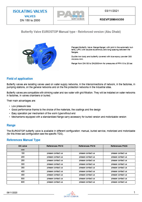
Butterfly Valve EUROSTOP Manual type - Reinforced version (Abu Dhabi)Flanged Butterfly Valve (flange-flange) with joint in the automatic but-terfly (JPA) with double eccentricity and long spacing between theflanges.Ductile iron body and butterfly covered with blue epoxy powder 300microns mini.Range from DN150 to DN2000mm for pressures of PFA10 to 25 bar.Field of applicationButterfly valves are isolating valves used on water supply networks, in the interconnections of network, in the factories, in pumping stations, on the general networks and on the fire protection networks in the industrial sites.Butterfly valves are compatible with drinking water and raw water with grid filtration. They will be installed on water networks in factories, in valves chambers or buried.Their main advantages are:•Low pressure loss•Good performance thanks to the choice of the materials, the coatings and the design•Easy operation per mechanism of the worm type/without end•Mechanisms equipped with a standardized flange carry-accessory for buried version and motorizable version RangeThe EUROSTOP butterfly valve is available in different configuration: manual, buried service, motorized and motorizable (for this three last configuration see the specific TDS).References Manual TypeMaterial and coatingValve equipped with 4 holes for the lifting of the valves DN>600. The gear box of the mechanism is in ductile iron FGS 400-15 type.Dimensions and massManual Version PN10Manual Version PN16Manual Version PN25Gearbox type and handwheel Manual type PN10Manual type PN16Manual type PN25Applicable StandardsHydraulic testEvery single butterfly valve is subjected to hydraulic final test with the purpose of verifying the accordance with the prescrip-tions ISO 5208:•Body test at 1,5 time the PFA (open valve);•Seat test at 1,1 time the PFA (closed valve).Product test•Control of manoeuvre torque (MOT and mST) as defined in the EN1074•Control of coating: test of thickness, holiday test, impact test, MIBK testConformity to the standardsProduct:•EN 1074 – 1 and 2•EN 593•ISO 10631Plant test:•ISO 5208Flanges dimension:•ISO 5752 series 14Flanges drilling:•EN 1092-2•ISO 7005-2Suitability for potable water:•Italian CM 102 of 02/12/78•Conformity to foreign norms: KTW (Germany), WRC (U.K.), ACS (France)MarkingOn the body like EN19:•Nominal diameter in mm (DN);•Nominal pressure in bar (PN);•Type of ductile iron;•Manufacturer’s logo;•Model code;•Fusion date.On the label like EN19:•Nominal diameter in mm (DN);•Nominal pressure in bar (PN);•Maximum operating pressure (PFA);•Closing direction;•Model code;•Manufacturing order, Order confirmation;•Manufacturer’s logo.On the disc:•Nominal diameter in mm (DN);•Nominal pressure in bar (PN);•Type of ductile iron;•Manufacturer’s logo;•Model code.The marking of the valves manufactured by Saint-Gobain refers to the EN 1074-2 and EN 19 international standards. Markings are either integral markings, cast in the body, or markings made on plates, securely fixed to the body, in accordance with the EN 19 standard specifications.Valve selectionThe butterfly valves are generally used as isolating devices type on/off. In some particular case, in which there’s low differ-ences of pressure and low flow rate variation can be used like regulating devices, considering the hydraulic parameters necessary to avoid the cavitation risk.To do the right dimensioning of butterfly valve it’s necessary to know the followings parameters:•Upstream hydrostatic pressure (that is the hydrostatic pressure with valve in closed position)•The maximum speed in water pipe (generally expressed in l/s) or the nominal diameter and the project flow rate from which it is gained the speed V=Q/AMoreover it’s necessary to control that the maximum speed in water pipe have to be equal or inferior to 5m/s, and the exercise temperature have to be between 0°C and 40 °C.Hydraulic featuresThe head loss Δh are variable in function of valve open degree and can be calculated with the following expression:with Δh = head loss (m), ζ = head loss coefficient (dimensional), v = nominal speed (m/s), g = 9,81 (m/s²)The head loss coefficient can be estimated from this diagram:Determinates the head loss Δh it’s possible to calculate the flow rate Q in m3/h with the following expression (the same expression can be used to, having the project flow rate Q, to determinate the head loss Δh without using the head loss coefficient):in which 10,2 is a corrective factor in meters, and Kv is the flow rate coefficient in m3/h, determinable from the following diagram in function of valve open degree:Example: Valve DN600 mm - Δh = 3 mFrom the diagram with valve open to 100% the coefficient Kv is 20000 m3/h. Using this date in the flow rate expression:Otherwise it’s possible to calculate the head loss with valve completely open, having the project flow rate Q, in function of DN, using the following diagram:CavitationIf the butterfly valve is used only like isolating device there’s not cavitation risk.In the particular case in which it’s used like regulating device, this can be possible only respecting the following parameters:•The valve open degree have to be between 30° and 90° (valve completely open)•The downstream pressure P2 have to be: P2 ≥ 0,7 .P1 - 2,8 with P1 upstream pressure.Instructions for useStorageThe butterfly valve will have to be held (if possible) in covered places, the most possible protected from the sun (maximum allowable temperature 70°C in accordance to EN 1074), from the rain and generally from the atmospheric agents. Moreover it will have to be avoided that the seal of the same air valves come to contact with powder or earth.InstallationThe butterfly valves are generally installed with retaining ring mounted in the opposite way respect to the direction of flow rate to permit the substitution of gasket without dismounting the valve from pipeline. In any case it is possible to install the butterfly valve with flow rate in opposite direction and also, if required, in vertical position. We recommend to install the butterfly with the operating device on the hydraulic right side of pipeline.It’s possible to install the butterfly valve both in chamber valve that underground (choosing the right configuration).We recommend to insert a dismounting joint for the operation of maintenance.MaintenanceThe butterfly valve does not require a particular maintenance, all parts subjected to wear are perfectly auto-lubricating. In any case, if for a long time will be not used, it is necessary to evaluate the functioning of valve doing (at least one time for year) some manoeuvre of opening-closing.All the maintenance operation have to be do after the total emptying of pipeline (no flow rate and pressure) to avoid every risk to the people during this operation.In presence of particularly exercise condition or damage due to external cause, it will be necessary some maintenance operation. In this case the particular shape of EUROSTOP butterfly valve permits the simple gasket substitution without the dismounting of valve from pipeline (if the dismounting joint is present).AccessoriesTo adapt the butterfly valves to the different exercise and installation conditions required, they can be equipped with particular accessories used in combination with control devices: please refer to data sheet for accessories.The technical features in this document are not contractual and can be changed without preliminary notification due to the continuous technical progress of product.。
蝶阀使用说明书

蝶阀使用说明书1.范围本说明书包括了公称通径DN50mm~1600mm(2”~64”)、公称压力PN1.0MPa~4.0MPa(ANSI CLASS150~300)法兰和对夹连接的手动、齿轮传动、电动和气动操作蝶阀。
2.用途2.1主要用于开启或关闭管道和设备的介质用,作调节、截流和止回使用。
2.2根据介质选用阀门的材质。
2.2.1碳钢阀门适用于水、蒸汽、油品等介质。
2.2.2不锈钢阀门适用于腐蚀性介质。
2.2.3铸铁阀门适用于水、气体介质。
2.3适用温度取决于阀座的材质。
PTFE(聚四氟乙烯)≤130℃不锈钢+复合体≤425℃橡胶≤85℃3.结构3.1蝶阀基本结构见图13.2易损件填料采用聚四氟乙烯或柔性石墨,密封可靠。
4.操作4.1手动操作阀门采用手柄或齿轮传动装置、电动或气动蝶阀由电动装置或气动装置驱动,使蝶板旋转90°开启或关闭阀门。
4.2对于手动(包括驱动装置的手轮)或扳手操作的蝶阀,除订货合同另有规定外,当面向手轮或扳手时,顺时针方向转动手轮或扳手阀门应为关。
4.3电动、气动蝶阀的开启、关闭指示由电动装置、气动装置上的位置指示器标识。
5.保管、保养、安装和使用5.1阀门应存放在干燥,通风的室内,阀门通道两端应堵塞。
5.2长期存放的阀门应定期检查,清除污物。
应特别注意密封面的清洁,防密封面的损坏。
5.3安装前应仔细核对阀门标志是否与使用要求相符。
5.4安装前应检查阀门通道和密封面,如有污垢,应使用清洁布擦拭干净。
5.5安装前检查填料是否压紧,应确保填料的密封性,同时不应妨碍阀杆的转动。
5.6安装时拧紧连接螺栓的拧紧力应均匀合适。
5.7本蝶阀可以安装水平、垂直的管道上,安装位置应保证使用维修更换方便。
5.8手动阀门在开启或关闭操作时,应使用手柄开、关,不得借用辅助杠杆或其它工具。
5.9阀门使用应定期检查,检查密封面有无磨损及垫片填料。
若损坏失效,应及时修理或更换。
5.10电动、气动阀门的传动装置,其保管、保养、安装和使用,请见“阀门电动装置使用说明书”及“阀门气动装置使用说明书”。
手动阀门使用说明

手动阀门使用说明
手动阀门是常用的阀门之一,包括有手动蝶阀、手动闸阀、手动球阀、手动截止阀等等,本文为您介绍一下手动阀门使用说明。
1、手动阀门的操作需要操纵阀门的人员握住手柄或手轮进行操作,不能够借助杠杆和长扳手来开关阀门,避免用力过猛对手柄或手轮造成损坏,更不能暴力操作,避免事故发生。
通常情况下,手柄的长度或手轮的直径小于320mm,只允许单人进行操作;手轮的直径等于或大于320mm时,允许两个人共同操作完成,也可以单人适当借助工具,杠杆或扳手进行操作,但要注意杠杆长度不可超过0.5m。
2、手动闸阀和手动截止阀都是借助手轮进行操作,在阀门完全开启或关闭之后,要回转1/4~1/2圈,让螺纹之间更好的密合,同时也能避免阀门拧得过紧出现损坏。
3、操作手动蒸汽阀门,在开启前要先对管道进行预热,排出管道中的凝聚水;开启阀门的速度要慢,以防水锤现象的发生,对阀门和管道设备造成损坏。
4、常开的手动阀门密封面上,很容易粘上杂质和脏物,在关闭闭合之前,微微开启一条缝,可以让高速流动的介质冲走这些异物,然后再轻轻关闭,提高密封效果。
5、在一些过高温介质的管道中,当手动阀门关闭之后,阀体内温度下降,因为热胀冷缩导致阀件收缩,密封面会出现一些细小的缝隙,阀门会出现泄漏。
在这种情况下,要在关闭手动阀门之后,过一会儿再关闭一次。
蝶阀产品使用说明书
蝶阀产品使用说明书
1 概述
1.1 主要用途及适用规范:
本阀门主要用于石油、天然气、油品、化工、冶金、城建及一般工业管道上作为切断装置。
1.2 品种及规格:
对夹式蝶阀,压力等级10MPa、通径DN200
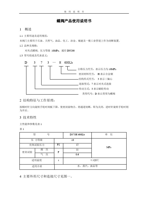
1.3 型号组成及代表意义:
D 3 7 3 — H 600Lb
公称压力代号:表示压力为10MPa
密封材料代号:H表示合金钢
结构形式代号:3表示三偏心
连接型式:7表示对夹式连接
传动方式:3表示蜗轮传动
类型代号:D表示类型为蝶阀
2 结构特征与工作原理:
按顺时针方向旋转手轮时闸板下降,使密封面吻合,将通道切断,即为关闭,逆时针旋转手轮时则为开启。
3 技术特性
主性能和参数见表1
表1
4 主要外形尺寸和连接尺寸见图一。
5 主要零件的材料
D373H-600Lb的主要零件材料见表2
表2
6 保管、使用和安装
6.1本阀门通道两端须堵密封盖,存放有干燥通风的室内。
长期存放,应经常检查,防止锈蚀6.2安装前,应将阀门清洗干净,并消除在运输过程中可能造成的缺陷。
6.3安装前,必须仔细核对阀门上的标志和铭牌是否符合使用要求。
6.4本阀门应安装在水平或垂直管道上的直立或侧卧位置,并便于检修和操作。
6.5本阀门在运行时应全开或全闭,不能作节流用,以免密封面受冲刷而加速磨损。
6.6传动部位应保持清洁,应定期加注润滑油。
7 故障分析与排除方法见表3
表3
图一。
手动蝶阀使用说明书
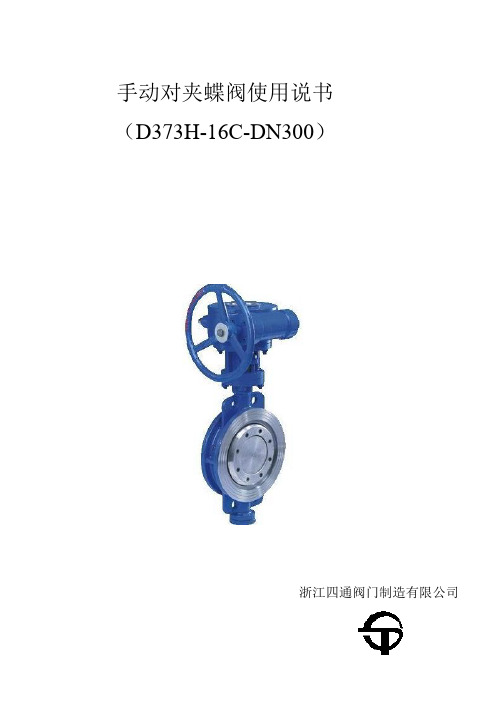
手动对夹蝶阀使用说书(D373H-16C-DN300)浙江四通阀门制造有限公司一、概述:碟阀是以蝶板作为关闭件的阀门。
蝶阀主要由阀体、阀杆、蝶板和密封圈等零件组成,属90°开关切断阀。
它借助手柄或驱动装置在阀杆上端施加一定的转矩传递给蝶板,使蝶板与阀体通道中心线重合或垂直,实现全开或全关动作。
蝶阀的主要功能是切断和接通管道中的流体,也可用于调节管路流量。
蝶阀主要特点:结构紧凑合理、操作扭矩较小、启闭迅速灵活、流阻小、流量系数大且维护使用方便。
此阀采用三偏心金属密封密封结构,其密封可达到零泄漏具有强制性密封性能效果。
蝶阀的连接形式可为对夹连接也可为双法兰连接。
其操作方式可采用手动、电动、气动和液动。
二、型号编制方法:三、主要技术参数:四、主要零件的材质:、结构及外形尺寸表:五、3" 80 49 114 125 380 190 152.5 127 M18 4-19 11 4" 100 56 127 145 415 229 190.5 157 M18 8-19 13 5" 125 64 140 165 455 254 216 186 M20 8-22 16 6" 150 70 140 175 545 279 241.5 216 M20 8-22 26 8" 200 71 150 210 645 343 298.5 270 M20 8-22 34 10" 250 76 160 250 695 406 362 324 M24 12-25 51 12" 300 86 178 285 830 483 432 381 M24 12-25 72 14" 350 92 190 320 900 533 476 413 M27 12-29 106 16" 400 102 216 355 980 597 540 470 M27 16-29 133 18" 450 114 222 380 1030 635 578 533 M30 16-32 176 20" 500 127 229 415 1110 699 635 584 M30 20-32 190 24" 600 154 267 475 1305 813 749.5 692 M33 20-35 394 30" 750 165 292 580 1525 985 914 857 M33 28-35 476 32" 800 190 318 630 1585 1060 978 914 M39 28-41 618 36" 900 203 330 680 1765 1168 1085 1022 M39 32-41 762六、蝶阀安装与维护注意事项:1.在安装时,碟板要停在关闭的位置上。
手动蝶阀尺寸规格表
手动蝶阀尺寸规格表手动蝶阀是一种常用的流体控制装置,广泛应用于各个领域。
手动蝶阀的尺寸规格非常重要,它直接关系到蝶阀的安装和使用效果。
下面是手动蝶阀尺寸规格表,以供参考和选择。
一、蝶阀尺寸规格1. 蝶阀的公称通径:蝶阀尺寸的主要参数是公称通径,用于表示蝶阀的口径大小。
常见的公称通径有DN40、DN50、DN65等,其中DN 代表公称直径。
2. 蝶阀的连接方式:手动蝶阀的连接方式有法兰连接、螺纹连接和焊接连接等。
不同的连接方式适用于不同的管道系统,需要根据实际情况选择。
3. 蝶阀的长度:蝶阀的长度是指蝶阀的整体长度,包括阀体和阀盘的长度。
根据不同的安装要求和流体控制需求,蝶阀的长度也会有所不同。
4. 蝶阀的材质:手动蝶阀的材质选择主要根据介质的性质和工作环境的要求。
常见的材质有铸铁、碳钢、不锈钢等。
不同的材质具有不同的耐腐蚀性、耐压性和耐磨性。
5. 蝶阀的密封性能:蝶阀的密封性能直接影响到阀门的使用寿命和流体的泄漏情况。
常见的密封形式有橡胶密封、金属密封和组合密封等。
6. 蝶阀的操作方式:手动蝶阀的操作方式有手动操作和电动操作两种。
手动操作可以通过手轮、手柄等进行,电动操作则通过电动装置进行控制。
7. 蝶阀的工作压力:蝶阀的工作压力是指蝶阀在正常工作状态下所承受的压力。
根据不同的工作压力要求,蝶阀的结构和材质也有所不同。
8. 蝶阀的适用温度:蝶阀的适用温度是指蝶阀可以正常工作的温度范围。
根据不同的介质和工作环境,蝶阀的适用温度也会有所不同。
二、选择蝶阀尺寸的注意事项1. 根据管道系统的流量和压力要求选择合适的蝶阀尺寸,保证流体的顺畅运行和控制效果。
2. 根据蝶阀的使用环境和介质的特性选择合适的材质,确保蝶阀具有良好的耐腐蚀性和耐压性。
3. 在选择蝶阀的连接方式时,要考虑管道系统的实际情况和安装要求,确保连接紧密可靠。
4. 注意蝶阀的操作方式,根据实际需求选择手动操作或电动操作,以提高控制的精度和效率。
手动蝶阀规格及使用

百度文库-让每个人平等地提升自我
一、概述:
碟阀是以蝶板作为关闭件的阀门。
蝶阀主要由阀体、阀杆、蝶板和密封圈等零件组成,属90°开关切断阀。
它借助手柄或驱动装置在阀杆上端施加一定的转矩传递给蝶板,使蝶板与阀体通道中心线重合或垂直,实现全开或全关动作。
蝶阀的主要功能是切断和接通管道中的流体,也可用于调节管路流量。
蝶阀主
\
要特点:结构紧凑合理、操作扭矩较小、启闭迅速灵活、流阻小、流量系数大
且维护使用方便。
此阀采用三偏心金属密封密封结构,其密封可达到零泄漏具
有强制性密封性能效果。
蝶阀的连接形式可为对夹连接也可为双法兰连接。
其
操作方式可采用手动、电动、气动和液动。
二、型号编制方法:
MOW
三、主要技术参数:
主要技术参数
四、主要零件的材质: 主要零件的材质
五、结构及外形尺寸表:
美标815W系
六、蝶阀安装与维护注意事项:
1. 在安装时,碟板要停在关闭的位置上。
2. 开启位置应按碟板的旋转角度来确定。
3. 带有旁通阀的蝶阀,开启前应先打开旁通阀
4. 重量大的蝶阀,应设置牢固的基础。
- 1、下载文档前请自行甄别文档内容的完整性,平台不提供额外的编辑、内容补充、找答案等附加服务。
- 2、"仅部分预览"的文档,不可在线预览部分如存在完整性等问题,可反馈申请退款(可完整预览的文档不适用该条件!)。
- 3、如文档侵犯您的权益,请联系客服反馈,我们会尽快为您处理(人工客服工作时间:9:00-18:30)。
手动对夹蝶阀使用简介(D373H-16C-DN300)
一、概述:
碟阀是以蝶板作为关闭件的阀门。
蝶阀主要由阀体、阀杆、蝶板和密封圈等零件组成,属90°开关切断阀。
它借助手柄或驱动装置在阀杆上端施加一定的转矩传递给蝶板,使蝶板与阀体通道中心线重合或垂直,实现全开或全关动作。
蝶阀的主要功能是切断和接通管道中的流体,也可用于调节管路流量。
蝶阀主要特点:结构紧凑合理、操作扭矩较小、启闭迅速灵活、流阻小、流量系数大且维护使用方便。
此阀采用三偏心金属密封密封结构,其密封可达到零泄漏具有强制性密封性能效果。
蝶阀的连接形式可为对夹连接也可为双法兰连接。
其操作方式可采用手动、电动、气动和液动。
二、型号编制方法:
三、主要技术参数:
830W 830L 公称通径DN(mm)
2"~36" 2"~36"
公称压力PN(Mpa)150Lb 300Lb
强度试验
试验压力
密封试验
适用介质水、蒸汽、油品、海水等
适用温度-29℃~425℃
四、主要零件的材质:
材料
零件名称
阀体WCB、304、316、316SS、CF8M
WCB、304、316、316SS、CF8M 蝶板
阀杆316、2Cr13、1Cr18Ni9Ti
316、氟塑料
密封圈
柔性石墨、氟塑料
填料
、
五、结构及外形尺寸表:
公称通径结构长度外形尺寸连接尺寸参考重量
(标准值)(参考值)(标准值)(kg)
L L1 H H0 D D1 D2 M Z-d
2" 50 43 108 110 345 152 92 M18 4-19 9 3" 80 49 114 125 380 190 127 M18 4-19 11 4" 100 56 127 145 415 229 157 M18 8-19 13 5" 125 64 140 165 455 254 216 186 M20 8-22 16 6" 150 70 140 175 545 279 216 M20 8-22 26 8" 200 71 150 210 645 343 270 M20 8-22 34 10" 250 76 160 250 695 406 362 324 M24 12-25 51 12" 300 86 178 285 830 483 432 381 M24 12-25 72 14" 350 92 190 320 900 533 476 413 M27 12-29 106 16" 400 102 216 355 980 597 540 470 M27 16-29 133 18" 450 114 222 380 1030 635 578 533 M30 16-32 176 20" 500 127 229 415 1110 699 635 584 M30 20-32 190 24" 600 154 267 475 1305 813 692 M33 20-35 394 30" 750 165 292 580 1525 985 914 857 M33 28-35 476 32" 800 190 318 630 1585 1060 978 914 M39 28-41 618 36" 900 203 330 680 1765 1168 1085 1022 M39 32-41 762
六、蝶阀安装与维护注意事项:
1.在安装时,碟板要停在关闭的位置上。
2.开启位置应按碟板的旋转角度来确定。
3.带有旁通阀的蝶阀,开启前应先打开旁通阀。
4.重量大的蝶阀,应设置牢固的基础。