labview入门总结
LabVIEW教程之LabVIEW入门
LabVIEW教程之LabVIEW入门1LabVIEW第章虚拟仪器及入门1.1虚拟仪器概述virtual instrumention虚拟仪器()是基于计算机的仪器。
计算机和仪器的密切结合是目前仪器发展的一个重要方向。
粗略地说这种结合有两种方式,一种是将计算机装入仪器,其典型的例子就是所谓智能化的仪器。
随着计算机功能的日益强大以及其体积的日趋缩小,这类仪器功能也越来越强大,目前已经出现含嵌入式系统的仪器。
另一种方式是将仪器装入计算机。
以通用的计算机硬件及操作系统为依托,实现各种仪器功能。
虚拟仪器主要是指这种方式。
下面的框图反映了常见的虚拟仪器方案。
Êý??ÐÅÊý?Ý?âºÅ?Ý?ÉÐéÄâÒÇÆ?Ã??å?Ôµ?????ÏóÀíÀí??虚拟仪器的主要特点有:,尽可能采用了通用的硬件,各种仪器的差异主要是软件。
,可充分发挥计算机的能力,有强大的数据处理功能,可以创造出功能更强的仪器。
,用户可以根据自己的需要定义和制造各种仪器。
虚拟仪器实际上是一个按照仪器需求组织的数据采集系统。
虚拟仪器的研究中涉及的基础理论主要有计算机数据采集和数字信号处理。
目前在这一领域内,使用较为广泛的计算机NILabVIEW语言是美国公司的。
2070虚拟仪器的起源可以追朔到世纪年代,那时计算机测控系统在国防、航天等领域PCMicrosoft已经有了相当的发展。
机出现以后,仪器级的计算机化成为可能,甚至在公司WindowsNIMacintoshLabVIEW2.0的诞生之前,公司已经在计算机上推出了以前的版本。
LabVIEW对虚拟仪器和长期、系统、有效的研究开发使得该公司成为业界公认的权威。
labview学习总结

labview学习总结转眼间已经学习labview一个多月了,因为在学校里没有学习过这门课程,其他的编程语言掌握的也不是很好,可以说是一点编程的基础也没有,所以在这期间让我遇到了很多的困难。
不过最后经过努力也都解决了。
下面是我对这段时间学习的一个总结。
首先我们要知道labview是什么。
他是图形化的程序语言,又称为“G”语言。
使用这种语言编程时,基本上不写程序代码,取而代之的是流程图。
他的运行机制包括前面板和程序框图,前面板是图形用户界面,也就是VI的虚拟仪器面板,这一界面上有用户输入和显示输出两类对象,具体表现有开关、旋钮、图形以及其他控制(control)和显示对象(indicator)。
程序框图也就是我们所说的后台,在那里我们可以进行程序的编写与修改。
labview的操作模板:工具模板,提供了创建,调试和修改vi程序的工具。
控制模板,给前面板设置输出和控制输入对象。
功能模板,创建流程图程序的工具。
labview的函数库包括数据采集、GPIB、串口控制、数据分析、数据显示及数据存储,等等。
labview也有传统的程序调试工具,如设置断点、以动画方式显示数据及其子程序的结果、单步执行等等,便于程序的调试。
以上这些是labview的基础知识。
经过这一个多月的学习,让我对labview开始入门了。
记得刚开始接触时,好多的控件都不知道在哪里去找,所以即使是对照着实例去编写一个程序也要好长时间,其次是对大部分的控件功能不了解,当遇到一个程序时不知道要用到哪些个控件。
所以我觉得要想学好labview我们必须要彻底熟悉了解每一个控件的功能。
现在我对大部分的常用控件已经基本上了解了他的功能,比如数组和簇,字符串、VISA函数、程序结构等。
在这段时间我还学会了如何创建子vi以及调用,这也是labview的基础,使用子vi可以使我们的程序更加清晰,对于修改也比较方便。
虽然说掌握了一些基础知识,但是还是有好多的不足,比如说要按顺序执行一段程序时我就往往忘掉加上顺序结构,即使程序运行是正确的,但是结果会出现随机性。
LabVIEW虚拟仪器程序设计从入门到精通
人民邮电出版社
1局部变量:1.层叠式顺序结构中,对于不同帧之间传递数据利用数据局部变量;2当一个控件既作为输入控件,又作为输出控件的时候利用局部变量;3在不同循环体之间的数据传递。
2全局变量:在不同的VI之间传递数据,但是对于内存资源的占用很大;
3共享变量:在不同的计算机或者网络之间共享。
4顺序结构强制破坏了LabView从左到右的数据流编程习惯,在平铺式结构中可以做到从右到左。
顺序结构破坏了LabView的优点之一:并行运行机制,因此一般不太提倡。
5那么程序中需要利用顺序执行程序的时候我们一般认为控制数据依存关系,此时,是通过数据的到达而不是数据的值来触发新结构对象的执行,数据的接收对象不一定需要该数据的值。
事件结构
事件结构是一个非常强大的功能,为事件驱动,可用于编写等待事件发生的高效代码,代替循环检测事件是否发生的低效代码。
对比条件结构和事件结构,在条件结构中,系统采用轮询的方式来检测“单击”按钮是否发生,但是在事件结构的技术过程中,只有单击按钮被按下以后触发,才执行一次循环。
因此,事件结构在执行前面板UI接口事件具有很强大的优越性。
事件结构的建议:
●避免在循环外使用事件结构;
●在“值”改变事件分支中读取触发布尔控件的接线端;
●条件结构用于处理触发布尔操作的撤销操作;
●不要使用不同的事件数据将一个分支配置为处理多个过滤事件;
●避免一个事件分支中同时使用对话框和“鼠标按下?”过滤事件;
●避免在一个循环中放置两个事件结构。
利用公式节点可以有效简化数值中的公式的繁琐结构。
禁用结构一般用于系统调试,避免程序在编辑中不停的删除、复制和修改中产生不必要的错误。
labview总结(LabVIEW总结)

labview总结(LabVIEW总结)Chapter 1 Introduction1, the LabVIEW program is called virtual instrument (VI).2, LabVIEW creates a user interface (front panel) by displaying the space in the input control. An input device, such as a knob, a button, a turntable, etc.. An explicit control refers to a display device, such as a graphic, an indicator, etc.. When the front panel is created, you can add code, and use VI and structure to control objects on the front panel. Block diagram contains the code.3, when you open an existing file or a new VI file, the startup window disappears automatically. After the file is closed, the startup window pops up automatically. You can select the View menu in the front panel to display the startup window.4, add input controls for the front panel, which is equivalent to providing data to the program block diagram.5, take an example: create the generated signal and display it on the front panel.CTRL+E is used to convert between the front panel and the program block window.6, add the input control for the front panel, which provides data for the VI program block diagram. Right click on any blank space in the front panel or block diagram to display the space or function palette.7, change the type of signal: the program block has an icon labeled as the simulation signal and, by default, the simulation is a sine wave. But you can also modify the waveform. Note: This is the input signal, that is, its amplitude, frequency, and phase are inputs.8, the object on the program block diagram: if you want to change the amplitude of the signal through the knob, you must connect the two objects on the program block diagram. Indicates the positioning tool when the cursor is displayed as an arrow. When using the loop, place the loop part in the middle of the for loop (the gray box)9, custom knob input control: modify the properties of the knob control.Summary: new dialog box and VI templateThe new dialog box contains many VI templates. The VI template is used to help users create VI for routine measurement and other tasks. The VI template includes the Express, VI, functions, and front panel objects that initially create a regular measurement application.Front panel: the front panel is the VI user interface. The input control and display space is the interactive input port and output port of the VI, which is used to create the front panel. The input control and display space are located in the control palette. The input control mainly includes the knob, button, turntable and other input devices. The input controls simulatethe input devices together to provide data for the program block diagram of the VI. The display control refers to a display device, such as a diagram, an indicator light, etc.. The device that controls the output of an analog instrument, used to display the data of a program block diagram.Block diagram: program block diagram contains graphical source code (G code), you can determine the VI mode of operation. The block diagram code uses a graphical representation of the function to control the front panel object. The front panel object is shown as an icon terminal on the block diagram. Connect the wiring of the control to the ExpressVI, VI, and function by wiring. Data can be passed in: input control to VI and function, VI and function to display space, VI and function to other VI and functions. Data transfers between the block diagrams of nodes can determine the order of execution of VI and functions. This method is called data flow programming.The block diagram object includes: terminal and program block diagram node.The block diagram nodes include functions, sub - VI, Express, VI, and structure.Front panel and block diagram tools: when you move the cursor to the object in the front panel and block diagram, you can display the location tool. The cursor is displayed as an arrow, used for object selection, positioning, and resizing. Move the cursor to the end of the block diagram object to display the wiring tool. At this point, the cursor is displayed as a coil, used to connect objects on the program block diagram, allowingdata to flow between objects.ExpressVI: the ExpressVI on the function board is used for routine measurement tasks. When the ExpressVI is placed on the block diagram, the configuration dialog box of the ExpressVI can be displayed automatically. Each option in the dialog box is used to specify the behavior of ExpressVI.Shortcut: CtrlR run VI; CtrlZ revoked the previous operation; CtrlE switch between the panel and the diagram window; CtrlS save VI.10, VI / VI connection: the icon icon is a VI used by other VI interface, when the VI is called other VI so in other VI will show the VI icon, located on the front panel and the block diagram of the upper right corner. The connecting line, if the sub VI is called VI, Xu create a connection plate, the connecting plate is used to display all VI input controls and display control terminal, set the terminal every VI, echoing the VI front panel controls, similar to the list of parameters in a programming language.The wiring board receives data at its input, and then passes it through the input control of the front panel to the block diagram code, which is output from the display control of the previous panel. The wiring board can only be defined in the front panel.The second chapter creates VI1, click the button on the top left corner of the functionpalette to lock the floating function board.2, open the immediate help, and then cursor to the corresponding function, it will show its functional use.3, the Express VI can reduce the signal sampling by LabVIEW help search, and click Add to the program block button to add the Express VI to the program block diagram.4, create controls in the program block diagram:5, to create a complete VI program, including icons and connection boards, this VI can run by itself, or can be called by other VI, which contains icons and the VI of the connection board.6, the instructions in the property are displayed in the prompt help. The prompt is that the cursor points to the object and displays the tooltip after the program is run.The third chapter program structureI. cyclic structure.1, the for loop executes the object within the structure according to the set number of times, including two long integer parameters: the total number of cycles N and the current number of cycles I N. The following steps are needed to build the for loop structure.(1) place the for loop box. (2) add loop program. Adds a loopprogram object in the flowchart. Note: all objects in the loop program must be included in the box, otherwise it will not be considered a loop program. (3) set the number of cycles. There are two ways to set the cycle number, direct setting and indirect setting.The direct setting is the direct assignment of N to set the number of cycles. Right click on the N, select Create variables from the pop-up menu, and enter the numeric constant in the variable control. The indirect method is to control the number of cycles using the automatic indexing function of the cyclic structure. Notice that I started at 0. N can be used as input values for objects.2, the while cycle(1) place the while loop box. (2) add a loop object. All objects in the loop program must be included in the box. (3) setting the judging method of cycle condition. Click the right mouse button at the end of the conditional menu to pop up the shortcut menu. You can choose conditional judgment. Select "create input control" and add a control to control the Boolean. At this point, a button appears in the front panel window to determine the condition control.。
LABVIEW基础知识
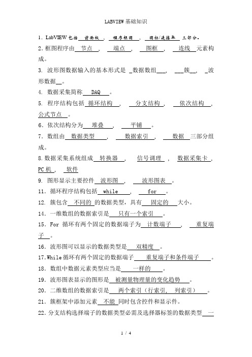
1.LabVIEW包括前面板, 程序框图, 图标/连接器三部分。
2.框图程序由节点 , 端点 , 图框 , 连线元素构成。
3. 波形图数据输入的基本形式是 _数据数组___, ___簇__, _波形数据__。
4. 数据采集简称 DAQ 。
5. 程序结构包括循环结构 , 分支结构 , 依次结构 , 公式节点。
6.依次结构分为堆叠 , 平铺。
7.数组由数据类型 , 数据索引 , 数据三部分组成。
8.数据采集系统组成转换器 , 信号调理 , 数据采集卡 , PC机 , 软件9. 图形显示主要控件波形图 , 波形图表。
11.循环程序结构包括 while , for 。
12. 簇包含不同的的数据类型,具有固定的大小。
14.一维数组的数据索引是只有一个索引。
15.For循环有两个固定的数据端子为计数端子 , 重复端子。
16.波形图可以显示的数据类型是双精度。
17.While循环有两个固定的数据端子重复端子和条件端子。
18.数组中数据元素类型应当是一样的。
19.波形图表显示的图形是被测量物理量的变化趋势。
20.二维数组的数据索引是两个索引(行索引, 列索引)。
21.簇框架中添加元素不能同时包含控件和显示件。
22.分支结构选择端子的数据类型必需及选择器标签的数据类型一样。
23.数组的长度在运行时不可以自由改变。
24.局部变量只能在同一个程序内部运用。
25.数据类型的种类数值型 , 布尔型 , 字符串型 , 数组型 , 簇型 ,图表型 , 图形型26.While和for循环的区分和特点区分:While循环只要满意退出的条件则退出相应的循环,否则变成死循环;而for循环是预先确定循环次数,当循环体运行指定的次数后自动退出循环。
特点:当不须要指定循环次数时,运用While循环。
27.移位寄存器的用法作用:运用移位寄存器可以在循环体的循环之间传递数据,其功能是将上一个循环的值传给下一次循环。
28.分支结构的选择端子是布尔类型。
labview入门
5.用 Text Tool(文本工具)创建文本。得到图标将如 6.单击OK,关闭编辑器。新创建的图标就显示在屏幕 1.打开 LabVIEW\Activity 目录中的Temp & 2.在前面板中,用鼠标右键单击窗口右上角的 下图所示。 右上角的图标窗口中。 Vol.vi,这是练习1-1做的程序。 3.删除默认图标。使用Select Tool(矩形框),单击并 标,在快捷菜单中选择 Edit Icon….,也可以双击 4.用 Pencil Tool (铅笔工具)绘制一个温度计。 拖动想要删除的部分,按下<Delete>。也可以通过双击 图标激活图标编辑器。注意只能在前面板中编辑 工具框中的阴影矩形删除图标。 图标和联接器。
如果一个VI程序存在语法错误,则在面板工具 3.断点与单步执行 条上的运行按钮会变成一个折断的箭头,表示 为了查找程序中的逻辑错误,有时希望流程图程序一个节 在LabVIEW的工具条上有一个画着灯泡的按 程序不能被执行。这时该按钮被称作错误列表。 4.探针 点一个节点地执行。使用断点工具可以在程序的某一地点 点击它,则LabVIEW弹出错误清单窗口,点击 钮,这个按钮叫做“高亮执行”按钮上。点 可用探针工具来查看当流程图程序流经某一根连接线时 中止程序执行,用探针或者单步方式查看数据。使用断点 其中任何一个所列出的错误,选用Find功能, 击这个按钮使它变成高亮形式,再点击运行 的数据值。从Tools工具模板选择探针工具,再用鼠标左 工具时,点击你希望设置或者清除断点的地方。断点的显 则出错的对象或端口就会变成高亮。 按钮,VI程序就以较慢的速度运行,没有被 建点击你希望放置探针的连接线。这时显示器上会出现 示对于节点或者图框表示为红框,对于连线表示为红点。 执行的代码灰色显示,执行后的代码高亮显 一个探针显示窗口。该窗口总是被显示在前面板窗口或 当VI程序运行到断点被设置处,程序被暂停在将要执行的 流程图窗口的上面。在流程图中使用选择工具或连线工 示,并显示数据流线上的数据值。这样,你 节点,以闪烁表示。按下单步执行按钮,闪烁的节点被执 具,在连线上点击鼠标右键,在连线的弹出式菜单中选 就可以根据数据的流动状态跟踪程序的执行。 行,下一个将要执行的节点变为闪烁,指示它将被执行。 择“探针”命令,同样可以为该连线加上一个探针 你也可以点击暂停按钮,这样程序将连续执行直到下一个
LabVIEW入门从零基础到快速上手
LabVIEW入门从零基础到快速上手LabVIEW是一种图形化编程语言和开发环境,用于控制和测量系统应用的快速原型设计、数据采集和分析。
本文将引导读者从零基础开始,逐步学习LabVIEW的基本概念和使用技巧,以帮助读者快速掌握LabVIEW的入门知识。
一、LabVIEW简介LabVIEW(Laboratory Virtual Instrument Engineering Workbench)是由美国国家仪器公司(National Instruments)开发的一种图形化编程语言和开发环境。
LabVIEW广泛应用于控制和测量系统领域,其独特的可视化编程方式使其成为工程师和科学家的首选工具。
二、LabVIEW安装和配置1. 下载LabVIEW安装程序并运行;2. 根据提示选择安装选项和目标文件夹;3. 完成安装后,启动LabVIEW,并进行基本配置,如选择界面语言、设置默认文件夹等。
三、LabVIEW界面介绍LabVIEW的界面由工具栏、项目资源、控制面板和主编辑区组成。
工具栏提供了常用的控件和工具,项目资源用于管理程序文件,控制面板用于运行程序,主编辑区用于编写和调试程序。
四、LabVIEW基本元素1. 控件:LabVIEW提供了丰富的控件,如按钮、滑动条、图形显示等,用于构建用户界面;2. 连接线:用于连接程序中的各个元素,形成数据流;3. 图标和面板:图标表示程序的功能,面板显示用户界面;4. 节点:用于执行具体的功能操作,如数学运算、控制结构等。
五、LabVIEW编程基础1. 数据流图:LabVIEW的编程模型基于数据流图,程序通过连续的数据流传递来实现功能;2. 程序结构:LabVIEW提供了各种结构化编程元素,如循环结构、条件结构等,用于控制程序流程和实现条件判断;3. 变量和数据类型:LabVIEW支持多种数据类型,如数值、字符串、数组等,变量用于存储和处理数据;4. VI(Virtual Instrument):VI是LabVIEW程序的基本单元,包含了一个完整的功能模块。
LABVIEW基础必学知识点

LABVIEW基础必学知识点
1. 控件与面板:学习如何在LabVIEW界面上添加控件(如按钮、滑块、文本框等)以及如何自定义面板布局和样式。
2. 数据流编程:熟悉数据流编程的概念及其在LabVIEW中的应用,了
解数据流图的基本结构和运行机制。
3. VI(虚拟仪器)的创建和调用:学习如何创建VI并将其用于调用
和组合成更复杂的程序。
4. 数据类型和数据结构:了解LabVIEW中的不同数据类型(如数字、
字符串、数组等),并学习如何使用数据结构来组织和处理数据。
5. 信号生成与处理:学习如何使用LabVIEW生成和处理模拟和数字信号,包括滤波、傅里叶变换等常用信号处理技术。
6. 串口通信与仪器控制:了解如何使用LabVIEW实现串口通信和控制
外部仪器,如通过串口与硬件设备进行通信或控制。
7. GUI设计和使用事件:学习如何设计漂亮的图形用户界面,并学习
如何使用事件结构实现用户交互和程序响应。
8. 数据存储与读取:了解如何使用LabVIEW将数据存储到文件中,以
及如何读取和处理已存储的数据。
9. 并行编程与多线程:学习如何使用并行编程来提高程序的性能和效率,并了解LabVIEW中多线程的概念和应用。
10. 错误处理和调试:掌握LabVIEW中的错误处理技术和调试工具,以及如何分析并解决程序中出现的错误。
以上是LabVIEW基础必学的知识点,掌握这些知识可以帮助你理解和使用LabVIEW进行数据采集、信号处理、仪器控制等应用。
- 1、下载文档前请自行甄别文档内容的完整性,平台不提供额外的编辑、内容补充、找答案等附加服务。
- 2、"仅部分预览"的文档,不可在线预览部分如存在完整性等问题,可反馈申请退款(可完整预览的文档不适用该条件!)。
- 3、如文档侵犯您的权益,请联系客服反馈,我们会尽快为您处理(人工客服工作时间:9:00-18:30)。
习题
创建一个 VI 程序,比较两个数, 如果 其中一个数大于或等于另一个数,则 LED 点亮。
用两种方法求出N!(for和while循环) 求一个二维数组的各元素之和。 求0-99之间所有偶数之和
程序结构
循环结构:While循环
循环变量
条件端子
程序结构
For循环
程序结构
移位寄存器
程序结构
顺序结构
簇
程序结构
Waveform类型
程序结构
图形显示
• Chart是将数据源(例如 采集得到的数据)在某一 坐标系中,实时、逐点地 显示出来,它可以反映被 测物理量的变化趋势 • Graph则是对已采集数据 进行事后处理的结果。它 先将被采集数据存放在一 个数组之中,然后根据需 要组织成所需的图形显示 出来。
2018/10/15
9
LabVIEW编程环境
LabVIEW 2012启动画面 (演示) 前面板和框图窗口 主菜单栏简介 快捷工具栏简介 LabVIEW的操作模板 工具模板(Tools Palette) 控制模板 ( Controls Palette ) 功能模板 ( Functions Palette )
•
程序结构
Chart和Graph的比较
程序结构
XY图形控件(XY Graph)
程序结构
强度图形控件(Intensity Graph)
程序结构
数字波形图控件(Digital Waveform Graph)
程序结构
字符串和文件I/O
组合字符串
Header SET Number 5.50 Trailer VOLTS
虚拟仪器入门基础
By 吕姝慧
2018/10/15
1
目 录
01 02 虚拟仪器简介 LabVIEW编程基础 03
2018/10/15
数据采集
2
01
虚拟仪器简介
2018/10/15
3
什么是LabVIEW ?218/10/154图形化编程
什么是虚拟仪器?
2018/10/15
6
02
LabVIEW编程基础
Chart Graph
Waveform(波形) XY
*
* *
Intensity(强度图) Digital(数字图)
*
* *
3D Surface(三维曲面)
*
3D Parametric(三维参变量)
*
3D Curve(三维曲线)
*
程序结构
Graph控件
程序结构
Chart的独有控件
• • 滚动条(Scrollbar) 它直接对应于显示缓冲器,通过它可以前后观察缓冲器内任何位置的数据。 刷新模式(Update Mode) Chart提供了三种画面的刷新模式,分别是 Strip Chart Mode(条壮图):它与纸带式图表记录仪类似。曲线从左到右 连续绘制,当新的数据点到达右部边界时,先前的数据点逐次左移。 Scope Chart Mode(示波器模式):它与示波器类似。曲线从左到右连续 绘制,当新的数据点到达右部边界时,清屏刷新,从左边开始新的绘制。它 的速度较快。 Sweep Chart Mode(扫描模式):与示波器模式的不同在于当新的数据点 到达右部边界时,不清屏,而是在最左边出现一条垂直扫描线,以它为分界 线,将原有曲线逐点向右推,同时在左边画出新的数据点。如此循环下去。 堆叠式图区(Stack Plots) 在相同的纵坐标下,由于各种测量信号的差异,将几条曲线显示在同一个图 区有困难时,可以组织出一种纵坐标相同,而有各自横坐标的堆叠式图区。
程序结构
读写普通文件
• Open/Create/Replace + Read/Write + Close • ASCII文件(*.txt)、二进制文件(*.dat)
程序结构
写文件的例子
ý ¾ Ê Ý µ ã ¸ ö Ê ý 20 Â ¶ Î È Chart 84.96 90.0 85.0 80.0 append to file? new file 75.0 70.0 39 59
程序结构
反馈节点
程序结构
Case结构
程序结构
通知事件
• 通知(Notify)描述了发生用户动作,例 如按下按钮,且LabVIEW已经处理的一类 事件 • Source=LabVIEW UI • Type=Value Change • CtlRef(Control Reference)这里是按钮 的Reference • OldVal和NewVal指示了事件发生前后的 控件值
程序结构
公式节点 • 公式节点(Formula Node )允许用户使用类似于多 数文本编程语言的语法, 编写数学表达式 • 每个语句须以分号结束, 类似C语言 • 输入输出变量大小写敏感
程序结构
数组、簇和波形
Array Constant 0 0 Array Constant ABC 0
Arr
AB
程序结构
过滤事件
• 过滤(Filter)事件描述了发生的用 户动作,并在LabVIEW处理之前反 馈给应用程序,程序可以干涉用户 动作 • 在Selector Label中以“?”结尾 区分Notify;左右边框均有事件数 据节点 • Char返回字符的ASCII码 • VKey返回按键类型:ASCII或Fn、 Up/Down、Ctrl、Shift等 • ScanCode返回按键在键盘上的代 码 • 可以修改或者放弃(Discard?)用 户动作
Constant 0
Array Constant ABC 0
Array Constant ABC
程序结构
初始化数组(Initialize Array)
程序结构
数组大小Array Size
程序结构
数组子集(Array Subset)
程序结构
索引数组(Index Array)
程序结构
多态化
程序结构
ä ³ Ê ö × Ö · û ´ ® SET 5.5000 VOLTS
ä ³ Ê ö ´ ® ³ ¤È ¶ 16
程序结构
字符串提取
程序结构 文件I/O
• 文件输入输出(I/O):存储数 据到磁盘文件中,或从磁盘文件 中读取数据 • 三个步骤:打开或创建、写入或 读取、关闭 • 支持文本字节流、二进制字节流 、数据日志(Datalog)、TDM (Test Data Exchange Format )、LVM(LabVIEW Measurement)等格式的数据 文件 • 可操作目录 • 读写配置文件(*.ini)