GF使用手册
TL5.0GF发电机说明书

TL5.0GF发电机说明书1、安全警告本机组在设计和制造过程中充分考虑了安全因素和对人身健康的影响。
使用者在使用前必须认真阅读以下内容并在操作过程中严格地遵守本手册规定的制度以避免事故发生。
因不可能预计所有使用之环境因此本手册所列举之事项亦非万全请用户结合本单位实际在使用过程中适当增减规定条款。
2、凡因违章引起的安全事故和人身健康损伤本公司概不负责。
发动机启动前所有的保护装置、特别是冷却风扇保护罩必须正确牢固安装。
在运转前所有的电器应检查是否联结牢固。
应保证所有地线接地良好可靠。
所有可以锁定的门和盖板在运转前应固定,保养维护时可能涉及到重型零件或危及生命的电气设备。
3、因此操作者必须经过适当的培训不要独自操作设备,以防万一发生意外时有人帮助处理。
如对设备内部进行清洁或修理,请将蓄电池负极线拆下并贴上警示标记以防发动机意外启动引起人身伤害。
4、保护罩机组设有对运转零件保护的保护罩。
开机时在机组旁工作的人员必须小心注意各活动机械部分可能对人身产生的危险。
在风扇或其他保护罩拆开的情况下切勿试图开机。
5、机组工作时要穿上工作服防止宽松衣服、手、长头发等绞入转动部位防止油、水、气和机身烫伤人体。
不要在冷却液未完全冷却时柠开散热器盖。
待冷却液冷却后先柠松盖子让里面的气体先行释放然后才能把盖护开。
机组运行时应将所有罩、盖与门板装妥以免发生事故。
6、化学品在机组上使用的燃料、机油、冷却液体、润滑剂及蓄电池的电解液都是工业上常用的然而使用处理不当亦会产生对人体的伤害。
7、不要用皮肤接触燃料、油、冷却液与电解液。
若有涉及应及时清洗必要时找医生处理。
高温的水和机油会导致严重的灼伤发动机未冷却时不要打开冷却系统与机油管路中的高热及高压的盖与堵头。
GfG 4035-22 操作手册说明书

Transmitter 4035-22 Operation ManualVersion 2.0Table of ContentsFor Your Safety (3)General Description (3)Electrical Connections (4)Zero Point Adjustment (4)Sensitivity Check (Calibration) (5)Technical Data (5)Troubleshooting (6)Warranty Statement (6)For Your SafetyAs with any piece of complex equipment, the GfG 4035 transmitter will do the job it is designed to do only if it is used and serviced in accordance with the manufacturer's instructions. Please protect yourself and your employees by following the instructions in this manual. All individuals who have or will have the responsibility for using and servicing this product must carefully read this manual. The warranties made by GfG with respect to the product are voided if functions or parameters are changed without the permission of GfG. They are also voided if the product is not used and serviced in accordance with the instructions in this manual. Failures or false alarms caused by interfering gases or electrical signals are not part of the warranty obligation. The above does not alter any statements by GfG regarding warranties, conditions of sale and/or delivery.General DescriptionThe 4035 transmitter uses an electrochemical sensor to convert a gas concentration into a linear 4–20mA electrical signal, and transmits it over a cable to a controller. It is a simple to connect, loop powered two wire transmitter.Electrical ConnectionsThe power connector is designed with a “quick disconnect” feature, which simplifies transmitter installation, replacement and service. The connector plug is easily removed from the transmitter by pulling straight up on the top of the power connector. This separates the bottom connection from the wiring connections to the plug. The connector plug is designed to be installed in only one direction (polarized) for safety reasons. Power is connected to the plug of the power connector by securing the stripped ends of the electrical cable using the two screws on the connector plug. Connect the supply wires (10–30 VDC) to the correct terminals on the connector plug (see diagram), and re-attach to the transmitter pc board by pressing back down on the pins from where it was removed.Caution: If the supply wires are reversed on the power connector, the transmitter will produce no current output.Zero Point AdjustmentThe 4035 transmitter uses a conveniently located set of two test terminals (see diagram) which provide a mV reading that corresponds to the 4–20 mA output. A reading of 40 mV on the test terminals corresponds to 4 mA, and 200 mV corresponds to 20 mA. This feature offers a quick and easy way to verify zero readings and gas response without having to disconnect wires and place current meters in line with the transmitter.Using a DC voltmeter set to the mV range, place the voltmeter’s leads in the 40–200 mV test terminals on the transmitter pc board. The reading should be approximately 40 mV. If you are unsure if the supply air is clean, flow impurity free air (zero air) into the sensing inlet using a calibration adapter and a 0.5 lpm fixed flow regulator, and allow the mV reading to stabilize. Please contact your GfG sales representative for zero gas ordering information if necessary. If the mV reading is not 40 mV, then the zero must be adjusted.To adjust the ZERO to 4mA (40 mV on the test terminals), slowly adjust the zero potentiometer on the transmitter board (see diagram) until a reading of 40 mV on the test terminals is reached (if the zero potentiometer cannot be adjusted to 40 mV, please contact GfG service for detailed instructions). This procedure will set the current output from the transmitter to 4 mA (zero).Sensitivity Check (Calibration)The 4035 transmitter uses a conveniently located set of two test terminals (see diagram) which provide a mV reading that corresponds to the 4-20 mA output. A reading of 40 mV on the test terminals corresponds to 4 mA, and 200 mV corresponds to 20 mA. This feature offers a quick and easy way to verify zero readings and gas response, without having to disconnect wires and place current meters in line with the transmitter.Using a DC voltmeter set to the mV range, place the voltmeter’s leads in the 40–200 mV test terminals on the transmitter pc board. Attach the calibration adapter to the sensing inlet. Flow 20 ppm calibration gas at 0.5 lpm (please contact your GfG sales representative for calibration gas ordering information if necessary). Allow the gas to flow across the sensor for at least 2 minutes or until the transmitter signal is stable, then check to see that the mV reading is at 50.6 mV.If the mV reading is not correct, adjust the Span potentiometer slowly until a mV reading of 50.6 is obtained (if the span potentiometer cannot be adjusted to the correct mV reading, please contact GfG service for detailed instructions). After the span adjustment is complete, remove the calibration gas, re-attach the supply air, and allow the transmitter current output to return to 40 mV (zero).Technical DataGas & Detection Range: Carbon Monoxide to 300 ppmDetection principle: ElectrochemicalGas supply: SuppliedResponse time T90: < 30 secondsOutput signal: 4–20mA LinearVoltage supply: 10–30 VDCSensor Cable: 18 AWG 2 conductor shielded Operating Temperature: -20 to 50° C (typical)Relative Humidity: 15–95% rh non-condensingGfG reserves the right to change part number, prices & technical information without notification.TroubleshootingSymptom Possible cause SolutionNo output∙Supply wires reversed∙Check wiring for proper polarityNo voltage to transmitter ∙ No power ∙Check for 10-30 VDC at powerconnectorNo response to gas ∙Sensor has expired∙Sensor wires disconnected∙Sensor not plugged incorrectly∙ Replace sensor∙Check sensor wiring∙Check sensor connection to transmitterpcbSensor will not calibrate ∙Sensor has expired∙Incorrect or bad span gas∙ Replace sensor∙Use correct concentration of span gasPlease contact GfG’s service department if you need additional help.Warranty StatementGfG Instrumentation warrants our products to be free from defects in material and workmanship when used for their intended purpose, and agrees to remedy any such defect or to furnish a new part (at the option of GfG Instrumentation) in exchange for any part of any product that we manufacture that under normal use is found to be defective; provided that the product is returned, by the purchaser, to GfG’s factory, intact, for our examination, with all transportation costs prepaid, and provided that such examination reveals, in our judgment, that it is defective. This warranty does not extend to any products that have been subjected to misuse, neglect, accident, or unauthorized modifications; nor does it extend to products used contrary to the instructions furnished by us or to products that have been repaired or altered outside of our factory. No agent or reseller of GfG Instrumentation may alter the above statements.1194 Oak Valley Drive, Suite 20Ann Arbor, Michigan 48108 USAPhone: (800) 959-0329 or (734) 769-0573Fax (734) 769-1888E-mail:****************Website: GfG reserves the right to change part numbers,prices, and/or technical information without notice. 7004-4035 110712。
GF仪表中文说明
第 2 步注意事项: 当显示“Enter Key Code”时,如果在 5 分钟 内没按任何键,显示会返回到视图菜单 (View)状态
标定菜单(CALIBRATE)中的第一项
第 3、4 步注意事项 • 参见 6、7 页了解所列菜单的完整内容与用法 • 在第 3 步的显示中,同时按上、下方向键便会返回到视图菜单
(VIEW)状态 • 如果 10 分钟内没按任何键,显示会返回到视图菜单(VIEW)状态
第 3 步:编辑完成了吗? 保存最后一项的设置内容后,同时按上、下方 向键返回到正常工作状态。
第 5、6 步注意事项: • 在编辑期间,所有输出功能都是有效的 • 只有正在闪动的位可被编辑 • 按右向键可以使闪动位循环移动 • 在按下 ENTER 键后,编辑好的值立即有效 • 如果在 10 分钟内没有按任何键,变送器会保存最后的修
2. 安装
• ProcessPro 系列变送器有两种类型:盘面安装式与现场安装式。盘面安装式带有变送器安装的必要 附件。操作手册中含有完整的盘面安装说明。
• 现场安装式变送器需要两种独立安装件中的一种。3-8051 一体式安装件将传感器与仪表连在一起, 置于同一包装内。3-8050 通用安装件可以使变送器安装在任何位置。
对于 2436/8512-XX,2540/2541,涡街流量传感器,以及任何输 出方波信号的传感器,最大电缆长度为 1000ft(300m)。
第 3 页共 8 页
+GF+SIGNET 8550-1
GEORG FISCHER +GF+
3.3 开路集电极输出信号
当过程变量高于或低于设定值时,开路集电极 输出信号可以用作开关量信号,或根据流量体 积量或流量发出脉冲信号。
GF标准表格中文说明书.docx

设定
Value Must be less than 3
PPM系数的值应在
0.00到
设置PPM的值小于3。
3.00之间
Value must be greater than 0 Custom(定制)的电级常数不
将电级常数的值设置为大
能被设为0
于0。
“Value must be 400 or less”脉冲比率不能大于400设置脉冲比率小于400
按上或下键手动调整电流输出在3.6mA-
21.00mA变化来检测输出回路。
按上或下键手动调整集电极开路输出状态。
故障处理
显示情况可能的原因解决建议
“_ _ _”
显示值超出范围。此种情况一般出现在测量范围接近探头范围的情况下。
检查探头的测量范围。
检查选项菜单 (option)
内小数位数的设置。
检查设定菜单
10.0000-40.0000
>
始值和最大输出点。如果改变电导的单位,
则此项必须重新设定。
Last
Cal(最后设定日期)
>
用该项记录重要的日期, 如每年重新验证或
计划维护日期。
OPTIONS
Display(显示)
Contrast :(对比度)
3>
Cond Decimal :(小数位数)
****.*>
5按上或者下键来修改闪烁的位。右箭头键转换闪烁的位。
6按ENTER键存储新的设定并回到步骤3
Calibrate Menu
Display(显示)
Flow Units:(流量单位)
GMP(加仑每分钟)>
Flow K-Factor:(流量系数)
GF仪表调试说明

流量计调试流量计调试分为三部分:一、流量标定—K系数。
二、单位调整。
三、4-20mA 量程设置。
各参数设置通过屏幕下方的四个按键来完成,按键说明见上图。
第一次通电时变送器会自动搜索探头,只需按ENT键即可完成探头选择。
一、流量标定长按ENT键三秒,进入菜单。
在屏幕下方分为五个主菜单“CAL”,”INPUT”,”LOOP”,“RELAY”,”OPTION”。
使用方向键右键将光标保持在”CAL”位置,按”ENT“进入标定菜单,按”下键“将菜单打到”KF 60.00”位置后按ENT”键进入菜单,此时屏幕上会有“————”显示,提示输入密码,9900变送器所有密码均为“上,上,上,下”,依次按“上”,“下”键进入子菜单后用上下键更换数字,右键选择数字的位数。
将数值输入后按”ENT“键保存,流量标定完成。
同时按住“上”和“下”键退出菜单。
二、单位设置重复第一步操作进入主菜单,用“右键”选择“INPUT”后按“ENT”进入输入选项,按“下键”使菜单到,按”ENT”进入设置流量单位,如需输入密码,也是“上,上,上,下”,流量默认单位为GMP,需将GMP改为“T/H”,用“上键”修改字母,“右键”来移动光标,修改完成后按“ENT”来保存。
再同时按住“上”和“下”键退出菜单。
三、4-20mA量程设置重复第一步操作进入主菜单,用“右键”选择“LOOP”后按“ENT”进入,按“下键”使菜单到,按“ENT”进入设置4mA对应的量程,设置完后“ENT”来保存。
然后按“上”“下”一次退出到,再按“下键”使菜单到,按“ENT”进入设置20mA对应的量程,设置完后按“ENT”保存。
再同时按住“上”和“下”键退出菜单。
到此流量设定完成。
电导率调试电导率调试分两部分:一、电极常数设定;二、4-20mA量程设定;设置方式与流量计相同。
一、电极常数设定首先将菜单选到“INPUT“,按”ENT“进入,用”下键“将菜单打到,按”ENT“进入,用”下“键来选择对应的C值。
GF流量计说明书.

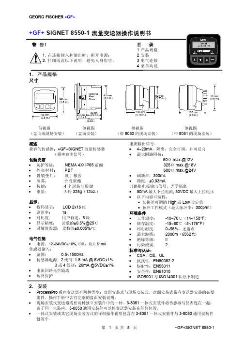
+GF+ SIGNET 8550-1 流量变送器操作说明书警告!1. 在连接输入和输出时,断开电源;2. 仔细阅读以下说明,避免人身伤害。
目录1 产品规格2 安装3 电气连接4 菜单功能1.产品规格尺寸前视图侧视图侧视图侧视图(盘面或现场安装(盘面安装(带8050的现场安装(带8051的现场安装概述兼容的传感器:+GF+SIGNET流量传感器(频率输出信号包装壳箱•防护等级: NEMA 4X/ IP65 前面•外壳材料: PBT•盘装垫片:氯丁橡胶•屏幕:合成聚酯•按键: 4个封装硅胶键•重量:大约325g(12oz.显示:•数码显示: LCD 2x16位•刷新率: 1s•对比度:用户自定,5级•显示精度:读数的±0.5%@25℃•灵敏度温漂:读数的±0.005%/℃电气性能•电源:12~24VDC±10%,可调,最大61mA传感器输入:•范围: 0.5~1500Hz•传感器电源:2线制: 1.5 mA @ 5VDC±1% 3或4线制:20mA @5VDC±1%•电流回路光学隔离•短路保护电流输出信号:• 4~20mA,隔离,完全可调,并可反向•最大回路阻抗:50Ω max.@12V325Ω max.@18V600Ω max.@24V•刷新率:300ms•精度:±0.03mA开路集电极输出信号,光学隔离• 50mA最大下拉电流, 30VDC最大上拉电压•以下内容可编程:•切换差可调的High或Low设定值•脉冲工作模式(最大脉冲率:300p/m环境条件•工作温度: -10~70℃(14~158°F•储存温度: -15~80℃(5~176°F•相对湿度: 0~95%,无露点•最大海拔: 2000m(6562 ft•绝缘等级: II•污染级别: 2标准与认证:• CSA,CE,UL•抗扰性:EN50082-2•辐射性:EN55011•安全性:EN61010• ISO9001与ISO14001认证下制造2.安装• ProcessPro系列变送器有两种类型:盘面安装式与现场安装式。
GF仪表中文说明
3. 将安装支架从仪表后面推上,直到快速固定卡片卡入仪表两 侧的槽中
4. 拆卸仪表时,在盘前用胶带暂时将仪表挡好,或在后部抓 牢。不要让仪表掉落。向外侧撑开快速固定卡片,抽出仪表 即可。
盘面安装详解
3. 电气连接
注意:在拆除接线之前如果没有将端子插孔完全打开,可能会永久地损坏仪表。
• 一体式安装或其它现场安装方式的详细操作说明包含在 3-8051 一体式安装件与 3-8050 通用安装件 包装中。
第 1 页共 8 页
+GF+SIGNET 8550-1
GEORG FISCHER +GF+
2.1 盘面安装
1. 盘装变送器需要一个 1/4DIN 开孔器。同时提供一张不干胶 模板,作为人工开孔时的安装指导。建议仪表各侧保留 1in.(25mm)的净边距。
3.2 传感器输入连接 接线提示
• 不要将传感器的电缆与 AC 电缆敷设在同一根电缆导管内。电子噪音会干扰传感器信号。 • 将电缆敷设在接地的金属电缆管中有助于防止电子噪音与机械损伤。 • 将电缆入口处密封,以防潮汽的侵害。 • 每个端子只能插入一根导线。如果两根导线接入同一端子,要在外部连好。
对于 515/8510-XX,525,2517,以及任何输出正弦波信号的传 感器,最大电缆长度为 200ft(61m)。
• Pulse 根据通过传感器的流量体积量,发出一个脉冲 信号。设定的体积量范围为 0.0001~99999。
设为 OFF 状态时,此项输出被隐藏。
输出信号被激励 输出信号复位
视图菜单(VIEW)
• 正常运行时,ProcessPro 系列仪表处于视图菜单(VIEW)显示状态。 • 在使用标定菜单(CALIBRATE)或选项菜单(OPTIONS)时,如果超过 10 分
通用汽车GF变速箱指导手册.doc
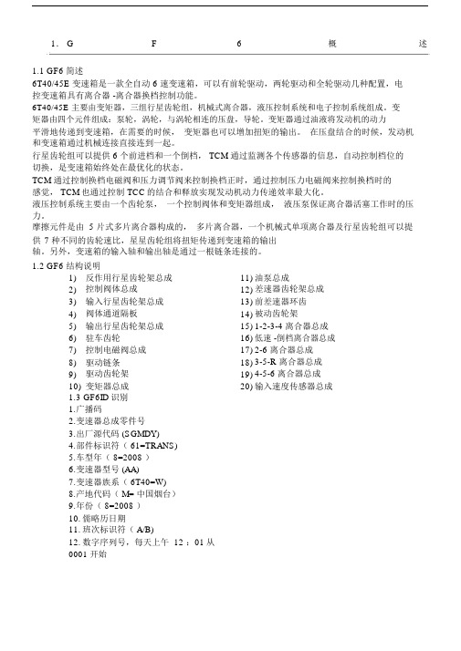
1. G F6概述1.1 GF6 简述6T40/45E 变速箱是一款全自动 6 速变速箱,可以有前轮驱动,两轮驱动和全轮驱动几种配置,电控变速箱具有离合器 -离合器换档控制功能。
6T40/45E 主要由变矩器,三组行星齿轮组,机械式离合器,液压控制系统和电子控制系统组成。
变矩器由四个元件组成:泵轮,涡轮,与涡轮相连的压盘,导轮。
变矩器通过油液将发动机的动力平滑地传递到变速箱,在需要的时候,变矩器也可以增加扭矩的输出。
在压盘结合的时候,发动机和变速箱通过机械连接直接连到一起。
行星齿轮组可以提供 6 个前进档和一个倒档, TCM 通过监测各个传感器的信息,自动控制档位的切换,是变速箱始终处在最优化的状态。
TCM 通过控制换档电磁阀和压力调节阀来控制换档正时,通过控制压力电磁阀来控制换档时的感觉, TCM也通过控制 TCC的结合和释放实现发动机动力传递效率最大化。
液压控制系统主要由一个齿轮泵,一个控制阀体和变矩器组成,液压泵保证离合器活塞工作时的压力。
摩擦元件是由 5 片式多片离合器构成的,多片离合器,一个机械式单项离合器及行星齿轮组可以提供7 种不同的齿轮速比,星星齿轮组将扭矩传递到变速箱的输出轴。
另外,变速箱的输入轴和输出轴是通过一根链条连接的。
1.2 GF6 结构说明1) 反作用行星齿轮架总成11) 油泵总成2) 控制阀体总成12) 差速器齿轮架总成3) 输入行星齿轮架总成13) 前差速器环齿4) 阀体通道隔板14) 被动齿轮架5) 输出行星齿轮架总成15) 1-2-3-4 离合器总成6) 驻车齿轮16) 低速 -倒档离合器总成7) 控制电磁阀总成17) 2-6 离合器总成8) 驱动链条18) 3-5-R 离合器总成9) 驱动齿轮架19) 4-5-6 离合器总成10) 变矩器总成20) 输入速度传感器总成1.3 GF6ID识别1.广播码2.变速器总成零件号3.出厂源代码 (SGMDY)4.部件标识符( 61=TRANS)5.车型年( 8=2008 )6.变速器型号 (AA)7.变速器族系( 6T40=W)8.产地代码( M= 中国烟台)9.年份( 8=2008 )10.儒略历日期11.班次标识符( A/B)12.数字序列号,每天上午 12 :01从0001 开始出厂源代码4-RamosArizpe ,墨西哥H-Ypsilanti ,密歇根州J-Windsor ,安大略州S-Strasbourg ,法国W-Warren ,密歇根州Y-Toledo ,俄亥俄州BRO-Boryeong ,韩国SGMDY- 中国山东烟台2. GF6参数2.1 GF6 技术参数6T40/456:前进档位变速箱型号T:前轮驱动40/45:扭矩参数变矩器直径236mm1st 4.584:12nd 2.964:13rd 1.912:1 变速箱档位4th 1.446:15th 1.000:16th 0.746:1R 2.940:11-2-3-4 离合器3-5-R 离合器4-5-6 离合器离合器名称2-6 离合器低速 -倒档离合器低速单向离合器(OWC )变速箱油型号DEXRONVI3. GF6控制功能3.1换档控制杆P 档( Park)P 档位置将车辆前轮锁住,同时防止车辆前后运动,P 档是启动车辆的最佳档位。