DSEI30-10A;DSEI30-10AR;中文规格书,Datasheet资料
uscar-30 中文版
4 一般要求概述 ................................................................................................................. 錯誤! 尚未定義書籤。
4.1 持續紀錄................................................................................................................. 錯誤! 尚未定義書籤。 4.2 樣品文件................................................................................................................. 錯誤! 尚未定義書籤。 4.3 樣品尺寸................................................................................................................. 錯誤! 尚未定義書籤。 4.4 默認測試公差......................................................................................................... 錯誤! 尚未定義書籤。 4.5 默認測試條件......................................................................................................... 錯誤! 尚未定義書籤。 4.6 設備......................................................................................................................... 錯誤! 尚未定義書籤。 4.7 測量方法................................................................................................................. 錯誤! 尚未定義書籤。 4.8 測量重復性&標准性............................................................................................. 錯誤! 尚未定義書籤。 4.9 一致性規定............................................................................................................. 錯誤! 尚未定義書籤。 4.10 樣品處置................................................................................................................. 錯誤! 尚未定義書籤。 4.11 零件耐久性 E.......................................................................................................... 錯誤! 尚未定義書籤。
IXGH20N100;中文规格书,Datasheet资料

IGBTV CES = 1000 V I C25 = 40 A V CE(sat) = 3.0 V t fi(typ) = 280 nsIXGH 20N100IXGT 20N100G = Gate, C = Collector,E = Emitter,TAB = CollectorTO-247 AD (IXGH)Features•International standard packages JEDEC TO-268 surface and JEDEC TO-247 AD•High current handling capability •MOS Gate turn-on -drive simplicity Applications•AC motor speed control •DC servo and robot drives •DC choppers•Uninterruptible power supplies (UPS)•Switched-mode and resonant-mode power supplies•Capacitor discharge Advantages•High power density•Suitable for surface mounting •Easy to mount with 1 screw,(isolated mounting screw hole)98620B (7/00)Symbol Test ConditionsCharacteristic Values(T J = 25°C, unless otherwise specified)min.typ.max.BV CES I C = 1 mA, V GE = 0 V 1000V V GE(th)I C = 250 m A, V CE = V GE2.55V I CES V CE = V CES T J = 25°C 250m A V GE = 0 VT J = 125°C1mA I GES V CE = 0 V, V GE = ±20 V ±100nA V CE(sat)I C= I C90, V GE = 15 V2.23.0VSymbol Test Conditions Maximum RatingsV CES T J = 25°C to 150°C1000V V CGR T J = 25°C to 150°C; R GE = 1 M W 1000V V GES Continuous ±20V V GEM Transient ±30V I C25T C = 25°C 40A I C90T C = 90°C 20A I CMT C = 25°C, 1 ms80A SSOA V GE = 15 V, T VJ = 125°C, R G = 47 W I CM = 40A(RBSOA)Clamped inductive load, L = 100 m H @ 0.8 V CESP C T C = 25°C150W T J -55 ... +150°C T JM 150°C T stg-55 ... +150°C Maximum Lead temperature for soldering 300°C1.6 mm (0.062 in.) from case for 10 sMaximum Tab temperature for soldering SMD devices for 10 s 260°CM d Mounting torque (M3) 1.13/10Nm/lb.in.WeightTO-247 AD 6g TO-2684gTO-268(IXGT)GE(TAB)IXYS reserves the right to change limits, test conditions, and dimensions. C (TAB)Preliminary dataRemarks: Switching times mayincrease for V CE (Clamp) > 0.8 • V CES ,higher T J or increased R G Remarks: Switching times mayincrease for V CE (Clamp) > 0.8 • V CES ,higher T J or increased R GSymbolTest ConditionsCharacteristic Values(T J = 25°C, unless otherwise specified)min.typ.max.g fs I C = I C90; V CE = 10 V,1216S Pulse test, t £ 300 m s, duty cycle £ 2 %I C(ON) V GE = 10V, V CE = 10V90A C ies 1750pF C oes V CE = 25 V, V GE = 0 V, f = 1 MHz100pF C res 38pF Q g 73nC Q ge I C = I C90, V GE = 15 V, V CE = 0.5 V CES 13nC Q gc 26nC t d(on)30ns t ri 30ns t d(off)350700ns t fi 280700ns E off 3.58.0mJ t d(on)30ns t ri 30ns E on 0.65mJ t d(off)700ns t fi 520ns E off 6.5mJ R thJC 0.83K/WR thCK(TO-247)0.25K/WInductive load, T J = 125°C I C = I C90, V GE = 15 V, L = 100 m H V CE = 0.8 V CES , R G = R off = 47 W Inductive load, T J = 25°CI C = I C90, V GE = 15 V, L = 100 m H,V CE = 0.8 V CES , R G = R off = 47 W limeterInches Min.Max.Min.Max.A 19.8120.320.7800.800B 20.8021.460.8190.845C 15.7516.260.6100.640D 3.55 3.650.1400.144E 4.32 5.490.1700.216F 5.4 6.20.2120.244G 1.65 2.130.0650.084H - 4.5-0.177J 1.0 1.40.0400.055K 10.811.00.4260.433L 4.7 5.30.1850.209M 0.40.80.0160.031N1.52.490.0870.102Dim.Millimeter Inches Min.Max.Min.Max.A 4.9 5.1.193.201A 12.7 2.9.106.114A 2.02.25.001.010b 1.15 1.45.045.057b 2 1.9 2.1.75.83C .4.65.016.026D 13.8014.00.543.551E 15.8516.05.624.632E 113.313.6.524.535e 5.45 BSC .215 BSC H 18.7019.10.736.752L 2.40 2.70.094.106L1 1.20 1.40.047.055L2 1.00 1.15.039.045L3 0.25 BSC .010 BSC L4 3.80 4.10.150.161TO-268AA (D 3 PAK)分销商库存信息: IXYSIXGH20N100。
GTAS-30B说明书(印刷版)

交流伺服驱动器使用手册目录第一章概述1.1产品介绍 (1)1.2产品外观 (2)1.3与安全有关的符号说明 (3)1.4警告标志的内容 (4)1.5安全注意事项 (4)1.6到货检查 (7)第二章产品规格2.1 驱动器规格 (8)2.2电机规格 (9)2.3隔离变压器 (14)第三章安装3.1 环境条件 (15)3.2 伺服驱动器安装 (16)3.3伺服电机安装 (18)第四章接线4.1标准接线 (20)4.2端子功能 (22)4.3 I/O 接口原理 (26)4.4 伺服电机接线 (29)第五章显示与操作5.1键盘操作 (31)5.2. 监视方式 (32)5.3 参数设置 (35)5.4 参数管理 (36)5.5 速度试运行.................................................................. .39 5.6 JOG运行.. (39)5.7电机测试 (40)5.8 其它 (40)目录第六章通电运行6.1 电源的连接 (41)6.2 通电试运行 (43)6.3 参数调整 (45)第七章参数7.1 参数一览表 (48)7.2 参数功能 (50)第八章报警与处理8.1 报警一览表 (59)8.2 报警处理方法 (60)第九章常见问题9.1 常见问题报警.............................................................. ..67 9.2 频繁出现Err-15、Err-30、Err-31、Err-32报警.. (67)9.3 型号代码参数与电机对照表 (68)交流伺服驱动器使用手册第一章概述1.1 产品简介:随着交流伺服技术的成熟稳定,产品性能不断提高,适应工业控制向高速度、高精度、高效率、数字智能化方向发展,同时随着伺服产品性价比的不断提升,伺服控制替代步进控制已成为产业发展趋势。
交流伺服技术已从军工航空航天领域广泛深入地渗透到各行各业,广泛应用于数控机床、纺织机械、轻工机械、网版印刷、包装机械、自动生产线等自动化领域。
DSEI30-06A

Millimeter Min. Max. 19.81 20.32 20.80 21.46 15.75 16.26 3.55 3.65 4.32 5.4 1.65 1.0 10.8 4.7 0.4 2.2 5.49 6.2 2.13 4.5 1.4 11.0 5.3 0.8 2.54
Inches Min. Max. 0.780 0.819 0.610 0.140 0.170 0.212 0.065 0.040 0.426 0.185 0.016 0.087 0.800 0.845 0.640 0.144 0.216 0.244 0.084 0.177 0.055 0.433 0.209 0.031 0.102
Fig. 4 Dynamic parameters versus junction temperature.
Fig. 5 Recovery time versus -diF/dt.
Fig. 6 Peak forward voltage versus diF/dt.
Dimensions
Dim. A B C D E F G H J K L M N
q q
Symbol
Test Conditions
Characteristic Values typ. max. 100 50 7 1.4 1.6 1.01 7.1 1 0.25 35 mA mA mA V V V mW K/W K/W K/W ns A
q
Antiparallel diode for high frequency switching devices Anti saturation diode Snubber diode Free wheeling diode in converters and motor control circuits Rectifiers in switch mode power supplies (SMPS) Inductive heating and melting Uninterruptible power supplies (UPS) Ultrasonic cleaners and welders
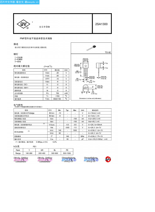
2SA1300中文资料(Dc Components)中文数据手册「EasyDatasheet - 矽搜」
V IC=-2A, I B=-50mA
-0.83 -1.5
V IC=-2A, V CE=-1V
-
1000
- IC=-0.5A, V CE=-1V
-
-
- IC=-2A, V CE=-1V
140
-
MHz IC=-0.5A, V CE=-1V
50
-
pF VCE=-10V, f=1KHz, I E=0
h分类
Min
2 Typ 2 Typ
.050 (1.27)
Typ
.022(0.56) .014(0.36)
.100 (2.54)
Typ
.022(0.56) .014(0.36)
.148(3.76)
321
.132(3.36)
.050 5 5 (1.27) Typ
Dimensions in inches and (millimeters)
Rank Range
FE1
Y
GR
140~280
200~400
BL 300~600
PE 500~1000
电气特性
(在25℃环境温度额定值除非另有规定)
特性
集电极 - 发射极击穿Volatge
发射极基极击穿电压
符号
Min
BVCEO -10
BVEBO -6
集电极截止电流
ICBO
-
发射极截止电流
集电极 - 发射极饱和电压
IEBO
-
(1)
VCE(sat)
-
基地发射极电压
VBE
-
DC电流增益
(1)
hFE1 140
(TA=25 oC)
符号
D R I L L S 2001年版商品目录说明书

D R I L L S2001N O T E SiI N D E XFractional Sizes,118°Point,Surface Treated . . . . . . . . . . . . . . . .1600 . . . . .1Fractional Diameters,118°Point,Bright .1600 . . . . .1Fractional Diameters,118°Point,TiN Coated . . . . . . . . . . . . . . . . . . . .1600 . . . . .1Wire Sizes,118°Point,Surface Treated .1601 . . . . .2Wire Sizes,118°Point,Bright . . . . . . . .1601 . . . . .2Wire Sizes,118°Point,TiN Coated . . . . .1601 . . . . .2Letter Sizes,118°Point,Surface Treated .1602 . . . . .3Letter Sizes,118°Point,Bright . . . . . . .1602 . . . . .3Letter Sizes,118°Point,TiN Coated . . . .1602 . . . . .3Metric Sizes,118°Point,Surface Treated 1603 . . . .4–6Metric Sizes,118°Point,Bright . . . . . . .1603 . . . .4–6J O B B E R S L E N G T H , H E A V Y D U T YHigh Speed SteelFractional Sizes,135°Split Point,Surface Treated . . . . . . . . . . . . . . . .1604 . . . . .7Fractional Diameters,135°Split Point,TiN Coated . . . . . . . . . . . . . . . . . . . .1604 . . . . .7Wire Sizes,135°Split Point,Surface Treated . . . . . . . . . . . . . . . .1605 . . . . .8Wire Sizes,135°Split Point,TiN Coated .1605 . . . . .8Letter Sizes,135°Split Point,Surface Treated . . . . . . . . . . . . . . . .1605-A . . . .9Letters Sizes,135°Split TiN Coated . . .1605-A . . . .9CobaltFractional Sizes,135°Split Point,Surface Treated . . . . . . . . . . . . . . . .1606 . . . .10Wire Sizes,135°Split Point,Surface Treated . . . . . . . . . . . . . . . .1607 . . . .11Letter Sizes,135°Split Point,Surface Treated . . . . . . . . . . . . . . . .1608 . . . .12Fractional Sizes,118°Point,Surface Treated . . . . . . . . . . . . . . . .1609 . . .13–14Fractional Sizes,118°Point,Bright . . . . .1609 . . .13–14Wire Sizes,118°Point,Surface Treated .1610 . . . .15Letter Sizes,118°Point,Bright . . . . . . .1611 . . . .16S C R E W M A C H I N E L E N G T H S , H E A V Y D U T YHigh Speed SteelFractional Sizes,135°Split Point,Surface Treated . . . . . . . . . . . . . . . .1612 . . . .17Fractional Sizes,135°Split Point,TiN Coated . . . . . . . . . . . . . . . . . . . .1612 . . . .17Wire Sizes,135°Split Point,Surface Treated . . . . . . . . . . . . . . . .1613 . . . .18Wire Sizes,135°Split Point,TiN Coated .1613 . . . .18Letter Sizes,135°Split Point,Surface Treated . . . . . . . . . . . . . . . .1614 . . . .19CobaltFractional Sizes,135°Split Point,Surface Treated . . . . . . . . . . . . . . . .1615 . . . .20Wire Sizes,135°Split Point,Surface Treated . . . . . . . . . . . . . . . .1616 . . . .21Letter Sizes,135°Split Point,Surface Treated . . . . . . . . . . . . . . . .1617. . . .22R E D U C E D S H A N KHigh Speed Steel1/2" Round Shank S &D,118°Point,Surface Treated . . . . . . . . . . . . . . . .1618 . . . .23S E T SDrill Sets . . . . . . . . . . . . . . . . . . . . . . . . .1619 . . .24–25LIST STYLENO.PAGE Drill Feeds And Speeds . . . . . . . . . . . . . . . . . . . . . . . .30Trouble Shooting Guide . . . . . . . . . . . . . . . . . . . . . . . .31Tap Drill Sizes For Metric Screw Threads . . . . . . . . . . .34Hardness Conversion Table . . . . . . . . . . . . . . . . . . . . .35LIST STYLENO.PAGEI N D E XSurface TreatedTiN Coatedii1J O B B E R S L E N G T H , H I G H S P E E D S T E E LG E N E R A L P U R P O S E , J O B B E R S L E N G T H D R I L L118°P o i n t , S u r f a c e T r e a t e d , B r i g h t , o r T i N C o a t e dG E N E R A L F E A T U R E S A N D A P P L I C A T I O N SDesigned for portable and machine drilling in a broad range of steel,ferrous and non-ferrous materials (bright finish in non-ferrous),under many different conditions.TiN coating with increased surface hardness allows for extended tool life,greater lubricity,betterchip ejection,increased productivity,and lower horsepower requirements.J O B B E R S L E N G T H , H I G H S P E E D S T E E L2J O B B E R S L E N G T H , H I G H S P E E D S T E E L3L e t t e r S i z e sG e n e r a l P u r p o s e , 118°P o i n tP A C K A G I N GA to N — 12 per package O to Z — 6 per packageEDP NO.EDP NO.J O B B E R S L E N G T H , H I G H S P E E D S T E E L4c o n t i n u e dM E T R I C , J O B B E R S L E N G T H D R I L L118°P o i n t (M a n u f a c t u r e d t o D I N S t a n d a r d s ),B r i g h t F i n i s h t o .50, S u r f a c e T r e a t e d .55 a n d L a r g e rG E N E R A L F E A T U R E S A N D A P P L I C A T I O N SDesigned for portable and machine drilling in a broad range of steel,ferrous and non-ferrous materials (bright finish in non-ferrous),under many different conditions.TiN coating with increased surface hardness allows for extended tool life,greater lubricity,better chip ejection,increased productivity,and lower horsepower requirements.J O B B E R S L E N G T H , H I G H S P E E D S T E E L5c o n t i n u ed Me t r i c S i z e sG e n e r a l P u r p o s e , 118°P o i n tFLUTE LENGTHOVERALL LENGTH EDP NO.c o n t i n u ed FLUTE LENGTH OVERALL LENGTH EDP NO.c o n t i n u e dJ O B B E R S L E N G T H , H I G H S P E E D S T E E L6J O B B E R S L E N G T H , H I G H S P E E D S T E E LM E D I U M D U T Y , J O B B E R S L E N G T H D R I L L135°S p l i t P o i n t , S u r f a c e T r e a t e d o r T i N C o a t e dG E N E R A L F E A T U R E S A N D A P P L I C A T I O N SMedium duty aircraft type B drills are designed for more demanding applications.The 135°split point is self-centering,reduces thrust is quick start-ing and highly accurate.ideal for portable or machine drilling of low tensile strength alloy material and stainless steels.TiN coating with increased surface hardness allows for extended tool life,greater lubricity,better chip ejection,increased productivity,and lower horsepower requirements.J O B B E R S L E N G T H,H I G H S P E E D S T E E LJ O B B E R S L E N G T H,H I G H S P E E D S T E E LH E A V Y D U T Y,J O B B E R S L E N G T H D R I L L135°S p l i t P o i n t,S t r a w F i n i s hG E N E R A L F E A T U R E S A N D A P P L I C A T I O N SHeavy duty aircraft type J drills are designed for tough,high tensile strength materials such as PH stainless steel, titanium,and inconel.The heat resistant cobalt material in combination with the 135°degree self-centering split point reduces thrust,is quick starting and highly accurate.Ideal for machine drilling.J O B B E R S L E N G T H,C O B A L T H I G H S P E E D S T E E LS C R E W M A C H I N E L E N G T H , H I G H S P E E D S T E E Lc o n t i n u e dG E N E R A L P U R P O S E , S C R E W M A C H I N E L E N G T H D R I L L H i g h S p e e d S t e e l , 118°P o i n t , S u r f a c e T r e a t e dG E N E R A L F E A T U R E S A N D A P P L I C A T I O N SPrimarily used in screw machines.Shorter flute and overall length provides increase rigidity in machine drilling resulting in lessdeflection,increased tool life,and better hole accuracy.Designed to drill in a wide variety of low tensile strength materials.S C R E W M A C H I N E L E N G T H,H I G H S P E E D S T E E LS C R E W M A C H I N E L E N G T H,H I G H S P E E D S T E E LS C R E W M A C H I N E L E N G T H,H I G H S P E E D S T E E LS C R E W M A C H I N E L E N G T H , H I G H S P E E D S T E E LH E A V Y D U T Y , S C R E W M A C H I N E L E N G T H D R I L L 135°S p l i t P o i n t , S u r f a c e T r e a t e d o r T i N C o a t e dG E N E R A L F E A T U R E S A N D A P P L I C A T I O N SHeavy duty,aircraft type C drills are ideal for portable drilling.The 135°split point is self-centering,reduces thrust,and is quick starting.The short rugged constructions performs will in a broad range of materials in the iron and steel families.TiN coating with increased surface hardness allowsfor extended tool life,greater lubricity,better chip ejection,increased productivity,and lower horsepower requirements.S C R E W M A C H I N E L E N G T H,H I G H S P E E D S T E E LS C R E W M A C H I N E L E N G T H,H I G H S P E E D S T E E LS C R E W M A C H I N E L E N G T H,C O B A L T H I G H S P E E D S T E E Lrugged construction performs well in a broad range of materials especially high alloys and work hardened material.T5F r a c t i o n a l S i z e sH e a v y D u t y,135°S p l i t P o i n tP A C K A G I N G1/16 to 19/64 — 12 per envelope5/16 to 1/2 — 6 per envelopeEDP NO.SIZE EQUIV.LENGTH LENGTH FINISH1/16.06255/81-5/8687005/64.078111/161-11/16687013/32.09383/41-3/4687027/64.109413/161-13/16687031/8.12507/81-7/8687049/64.140615/161-15/1668705S C R E W M A C H I N E L E N G T H,C O B A L T H I G H S P E E D S T E E LS C R E W M A C H I N E L E N G T H,C O B A L T H I G H S P E E D S T E E LR E D U C E D S H A N K D R I L L S , H I G H S P E E D S T E E L1/2 RO U N D S H A N K S & D D R I L L , R E D U C E D S H A N K D R I L LH i g h S p e e d S t e e l , 118°P o i n t , S u r f a c e T r e a t e dG E N E R A L F E A T U R E S A N D A P P L I C A T I O N SFor use in a 1/2" diameter portable drill chuck.Precision ground for a high degree of concentricity between the shank and body diameter.Ideal for drilling in low and medium tensile mon flute and overall lengths allow for minimal adjustment during tool change.S E T S118°J O B B E R S L E N G T H,G E N E R A L P U R P O S E,H I G H S P E E D S T E E L118°M E T R I C J O B B E R S L E N G T H,G E N E R A L P U R P O S E,H I G H S P E E D S T E E LS E T S135°M E D I U M D U T Y , J O B B E R S L E N G T H , H I G H S P E E D S T E E L135°H E A V Y D U T Y , J O B B E R S L E N G T H , C O B A L T H I G H S P E E D S T E E LS E T S118°G E N E R A L P U R P O S E,S C R E W M A C H I N E L E N G T H,H I G H S P E E D S T E E L135°M E D I U M D U T Y,S C R E W M A C H I N E L E N G T H,H I G H S P E E D S T E E L135°H E A V Y D U T Y,S C R E W M A C H I N E L E N G T H,C O B A L T H I G H S P E E D S T E E LS E T S27118°1/2 R E D U C E D S H A N K , H I G H S P E E D S T E E LT E C H N I C A L I N F O R M A T I O N28D RI L L N O M E N C L A T U R EAxis – The imaginary straight line which forms the longitudinal center line of the drill.Back Taper – A slight decrease in diameter from front to back in the body of the drill.Body – The portion of the drill extending from the shank or neck to the outer corners of the cutting lips.Body Diameter Clearance – That portion of the land that has been cut away so it will not rub against the walls of the hole.Chisel Edge – The edge at the end of the web that connects the cut-ting lips.Chisel Edge Angle – The angle included between the chisel edge and the cutting lip,as viewed from the end of the drill.Clearance – The space provided to eliminate undesirable contact between the drill and the workpiece.Clearance Diameter – The diameter over the cut away portion of the drill lands.Drill Diameter – The diameter over the margins of the drill measured at the point.Flutes – Helical or straight grooves in the body of the drill to provide cutting lips,permit removal of chips and allow coolant to reach the cutting lips.Flute Length – The length from the outer corners of the cutting lips to the extreme back end of the flutes.Helix Angle – The angel made by the leading edge of the land with a plane containing the axis of the drill.Land – the peripheral portion of the body between adjacent nd Width – The distance between the leading edge and the heel of the land measured at a right angle to the leading edge.Lead – The axial advance of the leading edge of the land in one turnaround the circumference.Lips – The cutting edges of a two-flute drill extending from the chisel edge to the periphery.Lip Relief – The axial relief angle at the outer corner of the lip.It is measured by projection into a plane,tangent to the periphery,at the outer corner of the lip.Margin – The cylindrical portion of the land which is not cut away to provide clearance.Overall Length – The length from the extreme end of the shank to the outer corners of the cutting lips.It does not include the conical shank end,often used on straight shank drills,or the conical cutting point.Point – The cutting end of a drill,made up of the ends of the lands and the web.In form it resembles a cone but departs from a true cone to furnish clearance behind the cutting lips.Point Angle – The angle included between the cutting lips,projected upon a plane parallel to the drill axis and parallel to the two cutting lips.Relative Lip Height – The difference in indicator reading between the cutting lips of the drill.It is measured at a right angle to the cutting lip at a specific distance from the axis of the drill.Relief –The result of the removal of tool material behind the cutting lip and leading edge of the land to provide clearance and prevent rub-bing.Web – The central portion of the body that joins the lands.The extreme end of the web forms the chisel edge on a two-flute drill.Web Thickness – The thickness of the web at the point,unless anoth-er specific location is specified.Web Thinning – The operation of reducing the web thickness,at the point,to reduce drilling thrust.T E C H N I C A L I N F O R M A T I O NS P E E D S F O R D R I L L I N GCUTTING POINTSPEED POINT ANGLEMATERIAL BEING DRILLED(SFM)STYLE(DEGREES)FEED RATE Aluminum Alloys200-300Conventional118Medium to Heavy Magnesium Alloys200-300Conventional118Medium to Heavy Brass and Bronze75-150Conventional118Medium to Heavy Cast IronSoft75-125Conv.or Split118 or 135Medium to Heavy Medium Hard50-100Conv.or Split118 or 135MediumHard Chilled10-20Conventional118Light to Medium Malleable75-125Conv.or Split118 or 135MediumSteelMild,.2 to .3 Carbon50-100Conventional118Medium to Heavy Medium,.4 to .5 Carbon45-80Conventional118MediumTool,1.2 Carbon40-60Conventional118MediumForgings40-60Conventional118MediumAlloy,300 to 400 BHN20-30Conv.or Split118 or 135MediumHigh TensileRc 35-4030-40Conv.or Split118 or 135MediumRc 40-4525-35Conv.or Split118 or 135MediumRc 45-5015-25Conv.or Split118 or 135Light to Medium Rc 50-557-15Conv.or Split118 or 135Light to Medium Maraging,Heat Treated7-20Conv.or Split118 or 135MediumMaraging,Annealed40-55Conv.or Split118 or 135Light to Medium Titanium AlloysCommercially Pure50-60Heavy Duty Split135Medium5AI-2Sn,8Al-1 Mo-1V20-45Heavy Duty Split135Medium2Fe-2Cr-Mo Annealed6Al-4V,4Al-4Mn,7Al-4Mo20-35Heavy Duty Split135Medium5Al-2Sn,8Al-1Mo-1V15-20Heavy Duty Split135Medium2Fe-2Cr-Mo SolutionTreated and AgedHigh Temperature AlloysCobalt Base,HS25,S816,V367-20Heavy Duty Split135MediumINCO 800,A286,N1557-20Heavy Duty Split135MediumNickel Base,Inconel 700,5-15Heavy Duty Split135MediumU500,Rene 41Monel Metal30-50Heavy Duty Split135Medium Stainless SteelFree Machining,303,416,42030-100Heavy Duty Split135MediumAustenitic,300 Series20-60Heavy Duty Split135MediumFerritic,400 Series20-60Heavy Duty Split135MediumMartensitic,Heat Treated10-30Heavy Duty Split135MediumPlastics and Related Materials100-200Low Angle90Medium to Heavy Zinc Alloys150-250Conventional118Medium to Heavy The speeds shown are for average conditions where coolant can be efficiently applied.Where the strength of the drill is not a critical factor and where the workpiece can be rigidly supported.When one or more of these conditions vary,the speeds must be adjusted accordingly.29T E C H N I C A L I N F O R M A T I O N30F E E D R A T E P E R R E V O L U T I O N F O R D R I L L SDRILL DIAMETER FEED PER REVOLUTIONRANGELIGHTMEDIUMHEAVY1/16 Thru 1/8.0005–.0010.0010–.0020.0020–.0030Over 1/8 Thru 1/4.0010–.0030.0030–.0050.0050–.0070Over 1/4 Thru 1/2.0030–.0050.0050–.0070.0070–.0090Over 1/2 Thru 3/4.0050–.0080.0080–.0110.0110–.0140Over 3/4 Thru 1.0080–.0110.0110–.0140.0140–.0170Over 1.0120–.0150.0150–.0200.0200–.0250The feed rates shown are for average conditions where coolant can be efficiently applied,where the strength of the drill is not a critical factor and where the workpiece can be rigidly supported.When one or more of these conditions vary; the feeds must be adjusted accordingly.S P E E D S A N D F E E D S F O R D E E P H O L E D R I L L I N GHoles which must be drilled three or more diameters deep fall into the “Deep Hole”drilling class and some adjustment of speeds and feeds is necessary.The deeper the hole,the greater the tendency for chip to pack and clog the flutes of the drill.This increases the amount of heat generated and prevents coolant from reaching the drill points.Heat buildup will eventually result in premature failure.Step drilling,that is,drilling a short distance and then retracting the drill,will often reduce the chip packing.The deeper the hole the more often the drill must be retracted.A reduction in speed and feed to reduce the amount of heat generated is generally required in most deep-hole applications where coolant cannot be effectively applied.S P E E D A N D F E E D R E D U C T I O N P E R C E N T A G E S F O R D E E P H O L E D R I L L I N GREDUCE REDUCE HOLE DEPTHSPEED BYFEED BY3 x Drill Diameter 10%10%4 x Drill Diameter 20%10%5 x Drill Diameter 30%20%6 x Drill Diameter 40%20%S P E E D C A L C U L A T I O N S F O R D R I L L I N GSurface Feet Per Minute (SFM) = .26 X RPM X Drill DiameterRevolutions Per Minute (RPM) =SFMDrill DiameterT E C H N I C A L I N F O R M A T I O NT R O U B L E S H O O T I N G G U I D E F O R D R I L L SPROBLEM PROBABLY CAUSESCorners break down.Cutting speed too high.Hard spots in material.Insufficient coolant at drill point.Flutes clogged with chips.Cutting lips chip.Too much feed.Lip relief too great.Margin chips.Oversize drill bushing.Drill breaks.Point improperly ground.Too much feed.Drill is dull.Flutes clogged with chips.Tang breaks.Imperfect fit between taper shank and socket caused by dirt or chips.Socket is burredor badly worn.Drill splits up center.Not enough lip relief.Too much feed.Drill will not enter work.Drill is dull.Not enough lip relief.Web is too heavy.Surface of hole is rough.Point improperly ground or dull.Insufficient coolant at drill point.Too much feed.Workholding device not rigid.Hole is oversize.Unequal point angles.Unequal length of cutting edges.Machine spindle bearings may be worn.Chip shape changes while drilling.Drill is dull.Cutting lips are chipped.Large chip coming out of one flute,Point is improperly ground and one lip is doing all of the cutting.small chip coming out of the other.31T E C H N I C A L I N F O R M A T I O N32T E C H N I C A L I N F O R M A T I O Ndrilled.The actual percent of thread engagement may be determined by pin gaging the hole.33T E C H N I C A L I N F O R M A T I O NT A P D R I L L S I Z E S F O R M E T R I C S C R E W T H R E A D S34T E C H N I C A L I N F O R M A T I O N35H A R D N E S S C O N V E R S I O N T A B L EROCKWELL HARDNESS TENSILE BRINELL STRENGTH CBAHARNESS(PSI)70–86.6––69–86.1––68–85.6––67–85.0––66–84.5––65–83.9––64–83.4––63–82.8––62–82.3––61–81.8––50–81.2–314,00059–80.7–306,00058–80.1–299,00057–79.6–291,00056–79.0–284,00055–78.5–277,00054–78.0–270,00053–77.4–263,00052–76.8500256,00051–76.3487250,00050–75.9475243,00049–75.2464236,00048–74.7451230,00047–74.1442223,00046–73.6432217,00045–73.1421211,00044–72.5409205,00043–72.0400199,000ROCKWELL HARDNESS TENSILE BRINELL STRENGTH CBAHARNESS(PSI)42–71.5390194,00041–70.9381188,00040–70.4371182,00039–69.9362176,00038–69.4353171,00037–68.9344166,00036–68.4336162,00035–67.9327157,00034–67.4319153,00033–66.8311149,00032–66.3301144,00031106.065.8294140,00030105.565.3286136,00029104.564.7279132,00028104.064.3271129,00027103.063.8264126,00026102.563.3271123,00025101.562.8253120,00024101.062.4247117,00023100.062.0243114,0002299.061.5237112,0002198.561.0231110,0002098.060.5226108,0001796.059.0215–1594,057.5204–1292.056.5194–990.055.0184–A Talbots Holdings Company200 Front Street Millersburg, Pennsylvania 17061 800-682-8832Fax: 717-692-270762-23047。
tslx

TestStation LX andTestStation 12X Technical Product DescriptiontTestStation LX andTestStation 12XTechnical Product DescriptionCopyright © Teradyne, Inc. 2004. All rights reserved under copyright laws of the United States and other countries. The technical data included herein, excluding computer software documentation, is subject to the LIMITED RIGHTS as set forth in FAR 52.227-15 (JUN 1987) and DFARS 252.227-7015 (JUN 1995). All technical data and computer software documentation contained herein is propri-etary and confidential to Teradyne, Inc. or its licensor. All computer software documentation contained herein is Commercial Com-puter Software Documentation, proprietary to Teradyne, Inc. or its licensor and furnished under limited license only. For solicitations issued by the United States, its agencies or instrumentalities (the "Government") on or after December 1, 1995 and the Department of Defense ("DoD") on or after September 29, 1995, the only rights provided in the Commercial Computer Software Documentation shall be those specified in a license customarily provided to the public by Teradyne, Inc. in accordance with FAR 12.212(a) and (b) (OCT 1995) or DFARS 227.7202-3(a) (JUN 1995). For solicitations issued before December 1, 1995 by the Government (other than DoD) use, duplication or disclosure of the documentation shall be subject to the RESTRICTED RIGHTS as set forth in subparagraph (c)(1) and (2) of the commercial computer software - restricted rights clause at FAR 52.227-19 (JUN 1987). For solicitations issued before September 29, 1995 by DoD: RESTRICTED RIGHTS LEGEND - The use, duplication, or disclosure by the Government is subject to restrictions as set forth in subparagraph (c)(1)(ii) of the Rights in Technical Data and Computer Software clause at DFARS 252.227-7013 (OCT 1988).The following are trademarks or registered trademarks of Teradyne, Inc.Product names listed are trademarks of their respective manufacturers. Company names listed are trademarks or trade names of their respective companies.The material in this manual is for informational purposes only and is subject to change, without notice. Teradyne assumes no respon-sibility for any error or for consequential damages that may result from the use or misinterpretation of any of the procedures in this publication.Access Analyzer™Ai-7 Series™Alchemist™APC™Argo™ATG XPRESS™AutoChecker™Autogen™AutoLoad™Autopub™Autotune™BasicSCAN™Bi4-Series™Bi-420™Boundary In-Circuit Test (BICT)™Boundary Scan Intelligent Diagnostics (BSID)™BusBust™BusScan™Call Sentinel™Cap Xpress™CapScan™CASTOR™CatSystem™CCU™Configural Recognition™CMU™Cshell™Component Designer (CDES)™D2B™Design-to-Build™D2B Alchemist™D2B DesignView™D2B ECO™D2B Strategist™D2B DFx™D-TRACKER™DBIU™Defect Display Station (DDS)™DeltaScan™Diamon™DigiBridge™DRMU™EJB-Tester™EJB-Monitor™EJB-Load™EJB-TestSuite™EKB-Test™E-MANAGER™E-SENTINEL™ENCOMPASS™FAST™FrameScan™FrameScan Plus™GENEVA®GenRad®GenRad CAT System™GR®GR-X90™GR-X130™GR-X130L™GR-X160L™GR-X1002™GR-X1500™GR-X1510™GR-X1525™GR-X1550™GR-X4005™GR-X4010™GR-X4011™GR-X7005™GR-X7010™GR2000™ GR4000™GR5000™GR 228X™GR & Des. ™GR AccelerATE®GR Advise™GR Navigate™GRNet™GR Producibility Analyzer™GR Stinger™GR SwitchManager™GR TestManager™GR TestStation™GR TestStation 12X™GR TestStation TSM™GR Versa™GR Versa OT™GR Xpert™GR X-Station 2D™GR X-Station 3-D™GridScan™Inline Device Programmer (ILDP) ™InterScan™Isolution™JUDGE™Junction Xpress™LASAR™L-Series™L200-Series™L300-Series™Lightning™M9-Series™MicroModal™Momentum™MultiScan™MultiScan II™Multi-Tester plus™NIM™NXR™Opens Xpress™Orient Xpress™Panel-Test™PinPoint™PRISM™Production Solutions International™Process Quality Manager™ProcessWatch™ProgramGuide™Program Xplorer™PrompTest™PXIscan™Quick-Check™QuickScan™RCU™RMU™SAC™Safecracker™SafeTest™Scan Pathfinder™Scavenger™Scot™ScratchProbe™SierraMate™SIMUL™Softbridge™Softbridge & Des.™ SoftProbe™Spectrum™Spectrum 8800-Series™SpeedPlus™Stinger™Stronghold™Syncload™The Technology of Knowledge®Teracode™Teradyne®TeraNet™Teradyne & Des. ™TestAdvisor™TestStudio™Test Toolbox™TEST XPRESS™TestLink™Testnet™TPS Converter Studio™TRACS™Vector Bus™Vector Performance (VP)™VICTORY™Virtual In-Circuit Test (VICT)™Virtual Component and Cluster Test (VCCT)™VRS™VXIscan®WaveScan™XFrame™XLT™Xpress Model™Xpress Start™Xpress Train™Xpress Transfer™Xpress Yield™XStation™XStation Combo™XStation HS™Z1800VP™Z1800-Series™Z1820VP™Z1840VP™Z1850VP™Z1880VP™Z1890VP™WARNINGS•Do not remove covers. Potentially lethal voltages are present inside the system. Observe all WARNING markings on the equipment and WARNING notices in the manual. If servicing is necessary, it should be performed only by a qualified person familiar with the electrical shock hazards present inside the system.•Grounding circuit continuity is vital for safe operation of the equipment. Never operate equipment with grounding conductor disconnected.•Safeguard your hands and fingers while handling any fixture or other accessory. Be sure it is securely supported if you reach under it. If it is heavy, you must have another person help to move it.•The symbol on equipment signifies that the manual contains information to prevent injury or equipment damage. Observe and heed all WARNING notices in the manuals and the equipment. WARNINGS call attention to personnel safety information.•Replace any fuse only with the same type and ratings as labeled on the equipment and/or listed in the manual.MISES EN GARDE•Ne pas enlever les couvercles. Les niveaux de tension se trouvant dans le système sont extrêmement dangereux. Respectez toutes les consignes de sécurité figurant sur l'équipement et les MISES EN GARDE données dan ce manuel. Seule une personne qualifée, connaisant les risques de décharge électrique du système, est autorisée à effecteur les opérations de nettoyage ou de réparation du système.•Le circuit doit être mis à la terre sans discontinuation pour garantir un fonctionnement sans danger de l'équipement. Ne jamais faire fonctionner l'équipement pendant que le raccord à la terre est déconnecté.•Protégez-vous les mains et les doigts pendant le maniement de tout dispositif de serrage ou autre accessoire.Assurez-vous que ceux-ci soient bien solidement fixés en place, avant de vous pencher sous eux. Si l'accessoire en question est trop lourd, faites-vous aider pour le déplacer.•Le symbole figurant sur l'équipement signifie que le manuel contient des informations permettant d'empêcher les accidents ou l'endommagement de l'équipement. Respectez toutes les consignes de MISES EN GARDE données dans le manuel et figurant sur l'équipement. Les MISES EN GARDE attirent l'attention sur la nécessité de se protéger.•Ne remplacez les fusibles qu'avec des fusibles du même type et de la même valuer que ceux mentionnés sur l'équipement et figurant dans le manuel.WARNHINWEISE•Abdeckungen nicht entfernen. Potentiell lebensgefährliche Spannungsbedingungen innerhalb des Systems vorhanden. Alle auf der Einrichtung befindlichen WARNMARKIERUNGEN und im Handbuch enthaltenen WARNHINWEISE beachten. Wartungsarbeiten dem qualifizierten Personal überlassen, das mit den innerhalb des Systems vorhandenen Gefahren eines elektrischen Schlags vertraut ist.•Die Erdung des Schaltungsdurchgangs ist eine Grundvoraussetzung für den sicheren Betrieb der Einrichtung.Einrichtung niemals ohne Erdleiter betreiben.•Hände und Finger bei der Handhabung einer Spannvorrichtung oder eines anderen Zubehörteils schützen.Sich vor der Plazierung der Hände unterhalb der Einrichtung vergewissern, daß die Einrichtung über ausreichenden Halt verfügt. Falls die Einrichtung schwer ist, sich von einer anderen Person beim Tragen helfen lassen.•Das auf der Einrichtung befindliche Symbol bedeutet, daß das Handbuch Informationen zur Verhinderung von Körperverletzungen oder Sachschäden enthält. Alle in den Handbüchern enthaltenen und auf der Einrichtung befindlichen WARNHINWEISE beachten und befolgen. WARNHINWEISE sollen auf Informationen zur persönlichen Sicherheit aufmerksam machen.•Sicherungen nur durch Sicherungen des gleichen Typs und der gleichen Nennleistung ersetzen. Auf der Einrichtung befindliche Etiketten und im Handbuch enthaltene Informationen zu Rate ziehen.!IEC417!IEC417!IEC417AVISOS•Não remova as tampas. Há voltagens potencialmente fatais presentes na parte interna do sistema. Observe todas as marcações de AVISOS no equipamento e discrições de AVISOS no manual. Se for necessário fazer manutenção, esta deve ser feita somente por uma pessoa qualificada familiarizada com os perigos de choques elétricos presentes na parte interna do sistema.• A continuidade do circuito de aterramento é vital para a operação segura do equipamento. Nunca opere o equipamento com o cabo de aterramento desligado.•Proteja as suas mãos e dedos ao operar qualquer dispositivo ou outro acessório. Certifique-se que ele esteja suportado com segurança se você tiver que alcançar algo debaixo dele. Se for pesado, você deve ter a ajuda de uma outra pessoa para movê-lo.•O simbolo no equipamento significa que o manual contém informações para prevenir ferimentos ou danos ao equipamento. Observe e preste atenção a todos os AVISOS nos manuais e no equipamento.Os AVISOS chamam a atenção a informações sobre a segurança pessoal.•Substitua qualquer fusivel somente com um do mesmo tipo e da mesma capacidade nominal como marcado no equipamento e listado no manual.ADVERTENCIAS•No quitar las tapas. En el interno del sistema hay voltajes potencialmente mortales. Obsérvense todos los rótulos de ADVERTENCIA presentes en el equipo, así como la descripción de las notas de ADVERTENCIA presentadas en el manual. De ser necesario, el servicio de mantenimiento deberá ser efectuado únicamente por personal calificado que esté familiarizado con los peligros de choque eléctrico presentes en el sistema.•La continuidad del circuito de puesta a tierra es de vital importancia para el functionamiento seguro del equipo.Nunca se debe usar el equipo con el conductor de puesta a tierra desconectado.•Protéjanse las manos y los dedos toda vez que sea necesario manipular un dispositivo u accesorio.Cerciorarse de que el mismo esté firmemente sujetado antes de proceder a trabajar debajo de él. Si el aparato u accesorio fuera pesado, pedir la ayuda de otra persona para moverlo.•El simbolo que aparece en el equipo significa que el manual contiene informaciones para evitar lesiones personales o daños al equipo. Obsérvense y préstese atención a toda las notas de ADVERTENCIA presentes en los manuales y en el equipo. Las ADVERTENCIAS sirven para llamar la atención sobre informaciones de seguridad para el personal.•Reemplazar los fusibles únicamente con otros del mismo tipo y capacidad, según lo indique el rótulo en el equipo y la descripción en el manual.CAUTIONS•Observe and heed all CAUTION notices in the manuals and on the equipment. CAUTIONS call attention to information about safeguarding equipment from damage.!IEC417!IEC417HANDLING PRECAUTIONS FOR ELECTRONIC DEVICES SUBJECT TO DAMAGE BY STATIC ELECTRICITYPlace instrument or module to be serviced, spare parts in conductive (anti-static) envelopes or carriers, hand tools etc. on a work surface defined as follows. The work surface must be conductive and reliably connected to earth ground through a safety resistance of approximately 250 kilohms. The sur-face must NOT be metal. (A resistivity of 30 to 300 kilohms per square inch is suggested.) Avoid placing tools or electri-cal parts on insulators.Ground the frame of any line-powered equipment, test instru-ments, lamps, soldering irons, etc., directly to earth ground. To avoid shorting out the safety resistance, be sure that grounded equipment has rubber feet or other means of insu-lation from the work surface. The module being serviced should be insulated while grounded through the power-cord ground wire, but must be connected to the work surface before, during and after any disassembly or other procedure in which the line cord is disconnected.Exclude any hand tools (such as non-conductive plunger-type solder suckers) that can generate a static charge.Ground yourself reliably, through a resistance, to the work surface; use, for example, a conductive strap or cable with a wrist cuff. The cuff must make electrical contact directly with your skin; do NOT wear it over clothing. (Resistance between skin contact and work surface through a commer-cially available personnel grounding device is typically 250 kilohms to 1 megohm.)If any circuit or IC packages are to be stored or transported, enclose them in conductive envelopes or carriers. Remove them only with the above precautions; handle IC packages without touching the contact pins.Avoid circumstances that are likely to produce static charges, such as wearing clothes of synthetic material, sitting on a plastic-covered stool (particularly while wearing wool), comb-ing your hair, or making extensive erasures. These circum-stances are most significant when the air is dry.When testing static sensitive devices, be sure DC power is on before, during, and after application of test signals. Be sure all pertinent voltages have been switched off while boards orcomponents are removed or inserted.ContentsUsing This ManualOverview . . . . . . . . . . . . . . . . . . . . . . . . . . . . . . . . . . . . . . . . . . . . . . . . . . . . . . . . . . . . . . . . . . . . . . xi Technical Support Center . . . . . . . . . . . . . . . . . . . . . . . . . . . . . . . . . . . . . . . . . . . . . . . . . . . . . . . . . xi How To Order Additional Documentation. . . . . . . . . . . . . . . . . . . . . . . . . . . . . . . . . . . . . . . . . . . . . . xii Patent Information . . . . . . . . . . . . . . . . . . . . . . . . . . . . . . . . . . . . . . . . . . . . . . . . . . . . . . . . . . . . . . . xiiIntroductionIntroduction . . . . . . . . . . . . . . . . . . . . . . . . . . . . . . . . . . . . . . . . . . . . . . . . . . . . . . . . . . . . . . . . . . .1 - 1 Standard System Configuration. . . . . . . . . . . . . . . . . . . . . . . . . . . . . . . . . . . . . . . . . . . . . . . . . . . .1 - 3 System Software . . . . . . . . . . . . . . . . . . . . . . . . . . . . . . . . . . . . . . . . . . . . . . . . . . . . . . . . . . .1 - 3 Test Hardware . . . . . . . . . . . . . . . . . . . . . . . . . . . . . . . . . . . . . . . . . . . . . . . . . . . . . . . . . . . . .1 - 4 Computer and Peripherals . . . . . . . . . . . . . . . . . . . . . . . . . . . . . . . . . . . . . . . . . . . . . . . . . . . .1 - 6 Service and Support . . . . . . . . . . . . . . . . . . . . . . . . . . . . . . . . . . . . . . . . . . . . . . . . . . . . . . . . .1 - 6 Optional System Software . . . . . . . . . . . . . . . . . . . . . . . . . . . . . . . . . . . . . . . . . . . . . . . . . . . . . . . .1 - 6 Optional System Hardware . . . . . . . . . . . . . . . . . . . . . . . . . . . . . . . . . . . . . . . . . . . . . . . . . . . . . . .1 - 7 Optional Computer Peripherals . . . . . . . . . . . . . . . . . . . . . . . . . . . . . . . . . . . . . . . . . . . . . . . . . . . .1 - 8 Overview of Software Licenses . . . . . . . . . . . . . . . . . . . . . . . . . . . . . . . . . . . . . . . . . . . . . . . . . . . .1 - 8Analog SubsystemOverview . . . . . . . . . . . . . . . . . . . . . . . . . . . . . . . . . . . . . . . . . . . . . . . . . . . . . . . . . . . . . . . . . . . . .2 - 1 Instrumentation . . . . . . . . . . . . . . . . . . . . . . . . . . . . . . . . . . . . . . . . . . . . . . . . . . . . . . . . . . . . . . . .2 - 2 ICA Module . . . . . . . . . . . . . . . . . . . . . . . . . . . . . . . . . . . . . . . . . . . . . . . . . . . . . . . . . . . . . . . .2 - 2 Digital Voltmeter (DVM) . . . . . . . . . . . . . . . . . . . . . . . . . . . . . . . . . . . . . . . . . . . . . . . . . . . . . .2 - 3 AC and DC Current Measure . . . . . . . . . . . . . . . . . . . . . . . . . . . . . . . . . . . . . . . . . . . . . . . . . .2 - 3 DC/AC Source Amplifiers . . . . . . . . . . . . . . . . . . . . . . . . . . . . . . . . . . . . . . . . . . . . . . . . . . . . .2 - 3 Impedance Measurement . . . . . . . . . . . . . . . . . . . . . . . . . . . . . . . . . . . . . . . . . . . . . . . . . . . . .2 - 4 Arbitrary Waveform Generator (AWG) . . . . . . . . . . . . . . . . . . . . . . . . . . . . . . . . . . . . . . . . . . .2 - 4 Digital Multimeter (DMM) . . . . . . . . . . . . . . . . . . . . . . . . . . . . . . . . . . . . . . . . . . . . . . . . . . . . .2 - 5 ICA Controls, Triggers, and Timers . . . . . . . . . . . . . . . . . . . . . . . . . . . . . . . . . . . . . . . . . . . . .2 - 5 ICA Instrument Multiplexer . . . . . . . . . . . . . . . . . . . . . . . . . . . . . . . . . . . . . . . . . . . . . . . . . . . .2 - 6 High Voltage Source . . . . . . . . . . . . . . . . . . . . . . . . . . . . . . . . . . . . . . . . . . . . . . . . . . . . . . . . .2 - 6 Calibration Daughter Board . . . . . . . . . . . . . . . . . . . . . . . . . . . . . . . . . . . . . . . . . . . . . . . . . . .2 - 6 Self-Test Circuits . . . . . . . . . . . . . . . . . . . . . . . . . . . . . . . . . . . . . . . . . . . . . . . . . . . . . . . . . . .2 - 6 IEEE-488 Multiplexer . . . . . . . . . . . . . . . . . . . . . . . . . . . . . . . . . . . . . . . . . . . . . . . . . . . . . . . .2 - 7ContentsRelay-Driver Function . . . . . . . . . . . . . . . . . . . . . . . . . . . . . . . . . . . . . . . . . . . . . . . . . . . . . . . .2 - 7 ICA Specifications . . . . . . . . . . . . . . . . . . . . . . . . . . . . . . . . . . . . . . . . . . . . . . . . . . . . . . . . . .2 - 8 High Voltage Source . . . . . . . . . . . . . . . . . . . . . . . . . . . . . . . . . . . . . . . . . . . . . . . . . . . . . . . .2 - 11 AWG Source . . . . . . . . . . . . . . . . . . . . . . . . . . . . . . . . . . . . . . . . . . . . . . . . . . . . . . . . . . . . . .2 - 14 Scanner Switching Matrix. . . . . . . . . . . . . . . . . . . . . . . . . . . . . . . . . . . . . . . . . . . . . . . . . . . . . . . .2 - 16 Switching Matrix Specifications . . . . . . . . . . . . . . . . . . . . . . . . . . . . . . . . . . . . . . . . . . . . . . .2 - 20 Measurement Methods and Specifications . . . . . . . . . . . . . . . . . . . . . . . . . . . . . . . . . . . . . . . . . .2 - 22 UUT Shorts Test . . . . . . . . . . . . . . . . . . . . . . . . . . . . . . . . . . . . . . . . . . . . . . . . . . . . . . . . . . .2 - 22 Opens Test . . . . . . . . . . . . . . . . . . . . . . . . . . . . . . . . . . . . . . . . . . . . . . . . . . . . . . . . . . . . . . .2 - 22 Capacitive Tests . . . . . . . . . . . . . . . . . . . . . . . . . . . . . . . . . . . . . . . . . . . . . . . . . . . . . . . . . . .2 - 23 Junction Xpress . . . . . . . . . . . . . . . . . . . . . . . . . . . . . . . . . . . . . . . . . . . . . . . . . . . . . . . . . . .2 - 25 Resistance Measurements . . . . . . . . . . . . . . . . . . . . . . . . . . . . . . . . . . . . . . . . . . . . . . . . . . .2 - 25 Impedance Measurements . . . . . . . . . . . . . . . . . . . . . . . . . . . . . . . . . . . . . . . . . . . . . . . . . . .2 - 32 AC Resistance . . . . . . . . . . . . . . . . . . . . . . . . . . . . . . . . . . . . . . . . . . . . . . . . . . . . . . . . . . . .2 - 32 Capacitance Test . . . . . . . . . . . . . . . . . . . . . . . . . . . . . . . . . . . . . . . . . . . . . . . . . . . . . . . . . .2 - 33 Inductance Test Procedures . . . . . . . . . . . . . . . . . . . . . . . . . . . . . . . . . . . . . . . . . . . . . . . . . .2 - 35 6-Wire AC Measurement . . . . . . . . . . . . . . . . . . . . . . . . . . . . . . . . . . . . . . . . . . . . . . . . . . . .2 - 36 Diode Test . . . . . . . . . . . . . . . . . . . . . . . . . . . . . . . . . . . . . . . . . . . . . . . . . . . . . . . . . . . . . . .2 - 37 Transistor Test. . . . . . . . . . . . . . . . . . . . . . . . . . . . . . . . . . . . . . . . . . . . . . . . . . . . . . . . . . . . . . . .2 - 38 NPN and PNP Tests . . . . . . . . . . . . . . . . . . . . . . . . . . . . . . . . . . . . . . . . . . . . . . . . . . . . . . . .2 - 38 FET Channel Impedance Test . . . . . . . . . . . . . . . . . . . . . . . . . . . . . . . . . . . . . . . . . . . . . . . .2 - 39 Zener Diode Test . . . . . . . . . . . . . . . . . . . . . . . . . . . . . . . . . . . . . . . . . . . . . . . . . . . . . . . . . .2 - 39 SCR Test . . . . . . . . . . . . . . . . . . . . . . . . . . . . . . . . . . . . . . . . . . . . . . . . . . . . . . . . . . . . . . . .2 - 40 Operational Amplifier Test . . . . . . . . . . . . . . . . . . . . . . . . . . . . . . . . . . . . . . . . . . . . . . . . . . .2 - 41 Analog Functional/Mixed Signal Testing . . . . . . . . . . . . . . . . . . . . . . . . . . . . . . . . . . . . . . . . . . . .2 - 42Digital SubsystemOverview . . . . . . . . . . . . . . . . . . . . . . . . . . . . . . . . . . . . . . . . . . . . . . . . . . . . . . . . . . . . . . . . . . . . .3 - 1 System Controller. . . . . . . . . . . . . . . . . . . . . . . . . . . . . . . . . . . . . . . . . . . . . . . . . . . . . . . . . . . . . . .3 - 2 Controller Functions . . . . . . . . . . . . . . . . . . . . . . . . . . . . . . . . . . . . . . . . . . . . . . . . . . . . . . . . .3 - 2 Clock/Sync/Trigger Logic. . . . . . . . . . . . . . . . . . . . . . . . . . . . . . . . . . . . . . . . . . . . . . . . . . . . . . . . .3 - 3 Timing Specifications for the CST . . . . . . . . . . . . . . . . . . . . . . . . . . . . . . . . . . . . . . . . . . . . . .3 - 4 Clock Drive/Synchronization for the CST . . . . . . . . . . . . . . . . . . . . . . . . . . . . . . . . . . . . . . . . .3 - 4 Trigger Pins for the CST . . . . . . . . . . . . . . . . . . . . . . . . . . . . . . . . . . . . . . . . . . . . . . . . . . . . . .3 - 5 Driver/Sensor Modules. . . . . . . . . . . . . . . . . . . . . . . . . . . . . . . . . . . . . . . . . . . . . . . . . . . . . . . . . . .3 - 6 Driver/Sensor Architecture . . . . . . . . . . . . . . . . . . . . . . . . . . . . . . . . . . . . . . . . . . . . . . . . . . . .3 - 7 Additional Features of Ultra 12X Pin Boards . . . . . . . . . . . . . . . . . . . . . . . . . . . . . . . . . . . . . .3 - 9 SafeTest. . . . . . . . . . . . . . . . . . . . . . . . . . . . . . . . . . . . . . . . . . . . . . . . . . . . . . . . . . . . . . . . . . . . .3 - 10ContentsAutomatic Driver Verification . . . . . . . . . . . . . . . . . . . . . . . . . . . . . . . . . . . . . . . . . . . . . . . . .3 - 10 Real-Time Backdrive Current Measurement Capabilities . . . . . . . . . . . . . . . . . . . . . . . . . . . .3 - 10 Closed Loop, Low Output Impedance Drivers . . . . . . . . . . . . . . . . . . . . . . . . . . . . . . . . . . . .3 - 10 Multi-Level Digital Isolation . . . . . . . . . . . . . . . . . . . . . . . . . . . . . . . . . . . . . . . . . . . . . . . . . . .3 - 10 Per Pin Programmable Logic Level Assignments . . . . . . . . . . . . . . . . . . . . . . . . . . . . . . . . .3 - 10 Programmable Backdrive Currents and Duration . . . . . . . . . . . . . . . . . . . . . . . . . . . . . . . . . .3 - 11 Specialized Digital Controller and Timing . . . . . . . . . . . . . . . . . . . . . . . . . . . . . . . . . . . . . . . .3 - 11Optional Test HardwareOverview . . . . . . . . . . . . . . . . . . . . . . . . . . . . . . . . . . . . . . . . . . . . . . . . . . . . . . . . . . . . . . . . . . . . .4 - 1 Analog Functional Test Module (AFTM) . . . . . . . . . . . . . . . . . . . . . . . . . . . . . . . . . . . . . . . . . . . . .4 - 1 AFTM Specifications . . . . . . . . . . . . . . . . . . . . . . . . . . . . . . . . . . . . . . . . . . . . . . . . . . . . . . . . .4 - 2 DC Voltage Measure . . . . . . . . . . . . . . . . . . . . . . . . . . . . . . . . . . . . . . . . . . . . . . . . . . . . . . . .4 - 2 AC Voltage Measure . . . . . . . . . . . . . . . . . . . . . . . . . . . . . . . . . . . . . . . . . . . . . . . . . . . . . . . .4 - 3 DC Source . . . . . . . . . . . . . . . . . . . . . . . . . . . . . . . . . . . . . . . . . . . . . . . . . . . . . . . . . . . . . . . .4 - 3 AC Source . . . . . . . . . . . . . . . . . . . . . . . . . . . . . . . . . . . . . . . . . . . . . . . . . . . . . . . . . . . . . . . .4 - 4 Sync Source . . . . . . . . . . . . . . . . . . . . . . . . . . . . . . . . . . . . . . . . . . . . . . . . . . . . . . . . . . . . . . .4 - 4 Instrument Multiplexer . . . . . . . . . . . . . . . . . . . . . . . . . . . . . . . . . . . . . . . . . . . . . . . . . . . . . . .4 - 4 Frequency/Time Interval Meter (FTM) . . . . . . . . . . . . . . . . . . . . . . . . . . . . . . . . . . . . . . . . . . .4 - 5 Deep Serial Memory . . . . . . . . . . . . . . . . . . . . . . . . . . . . . . . . . . . . . . . . . . . . . . . . . . . . . . . . . . . .4 - 5 DSM Applications . . . . . . . . . . . . . . . . . . . . . . . . . . . . . . . . . . . . . . . . . . . . . . . . . . . . . . . . . . .4 - 6 Custom Function Board (CFB). . . . . . . . . . . . . . . . . . . . . . . . . . . . . . . . . . . . . . . . . . . . . . . . . . . . .4 - 7 Custom Function Board Applications . . . . . . . . . . . . . . . . . . . . . . . . . . . . . . . . . . . . . . . . . . . .4 - 8 Vehicle Control Interface (VCI) . . . . . . . . . . . . . . . . . . . . . . . . . . . . . . . . . . . . . . . . . . . . . . . . .4 - 8 Frequency/Time Interval Instrument Module (FTI) . . . . . . . . . . . . . . . . . . . . . . . . . . . . . . . . . .4 - 8 FTI Specifications . . . . . . . . . . . . . . . . . . . . . . . . . . . . . . . . . . . . . . . . . . . . . . . . . . . . . . . . . .4 - 9 Duty Cycle . . . . . . . . . . . . . . . . . . . . . . . . . . . . . . . . . . . . . . . . . . . . . . . . . . . . . . . . . . . . . . .4 - 10 System Frequency/Time Meter (SFTM). . . . . . . . . . . . . . . . . . . . . . . . . . . . . . . . . . . . . . . . . . . . .4 - 10Unit Under Test Power SuppliesOverview . . . . . . . . . . . . . . . . . . . . . . . . . . . . . . . . . . . . . . . . . . . . . . . . . . . . . . . . . . . . . . . . . . . . .5 - 1 Programmable Voltage Power Supplies . . . . . . . . . . . . . . . . . . . . . . . . . . . . . . . . . . . . . . . . . . . . .5 - 1 Common Specifications . . . . . . . . . . . . . . . . . . . . . . . . . . . . . . . . . . . . . . . . . . . . . . . . . . . . . .5 - 2 Programmable Power Supply Specifications . . . . . . . . . . . . . . . . . . . . . . . . . . . . . . . . . . . . . .5 - 3 Optional Fixed Voltage Power Supplies. . . . . . . . . . . . . . . . . . . . . . . . . . . . . . . . . . . . . . . . . . . . . .5 - 4System Layout and Mechanical/Industrial SpecificationsSystem Layout. . . . . . . . . . . . . . . . . . . . . . . . . . . . . . . . . . . . . . . . . . . . . . . . . . . . . . . . . . . . . . . . .6 - 1 Power Bay . . . . . . . . . . . . . . . . . . . . . . . . . . . . . . . . . . . . . . . . . . . . . . . . . . . . . . . . . . . . . . . .6 - 1。
半导体传感器ADR03ARZ中文规格书

Three-Operand ShiftsSimilarly, a 4-bit upshift applied to a 16-bit value could be implemented as follows:R0.L = 0xB6A3 ; // Load value to be shiftedR1.H = R0.L << 0x04 ; // Perform left shift by 4As a result of this sequence, the 16-bit 0xB6A3 value in R0.L is left-shifted by four and stored to R1.H as 0x6A30. Register ShiftsRegister-based shifts use a data register to hold the shift magnitude. For ASHIFT, LSHIFT and ROT instructions performing register-based shifts, the shift magnitude must be in the lowest six bits of a low data register half(R[n].L). The upper 10 bits of R[n].L are masked off and ignored.The following is an example of a register-based 4-bit logical upshift:R0 = 0x0000B6A3 ; // Load value to be shiftedR2.L = 0x4 ; // Load shift magnitudeR1 = LSHIFT R0 by R2.L ; // Perform shiftAs the shift magnitude is positive, this sequence results in a logical left shift of the 0x0000_B6A3 input data by four, zero-filling the vacated lower four bits and storing the 0x000B_6A30 result to R1.For a register-based 4-bit arithmetic downshift, an example sequence is:R0 = 0xB6A30000 ; // Load value to be shiftedR2.L = -0x4 ; // Load shift magnitudeR1 = ASHIFT R0 by R2.L ; // Perform shiftAs the shift magnitude is negative, this sequence results in an arithmetic right shift of the 0xB6A3_0000 input data by four, sign-extending through the vacated upper four bits and storing the 0xFB6A_3000 result to R1.The ROT instruction uses the shifter to shift the input operand through the Arithmetic Status register's Condition Code bit (). When the shift is performed, the bit in inserted into the data between bit 0 and bit 31 of the original data. For example:R0 = 0xABCDEF12 ; // Load value to rotate through CCR2.L = 0x4 ; // Set rotate magnitudeR1 = ROT R0 by R2.L ; // Perform rotationAssuming that was 0 entering the above sequence, the positive magnitude in R2 results in a 4-bit left rotation being applied to the 0xABCD_EF12 input data, with the bit value of 0 appearing between bit 0 and bit 31 of the input data. The resulting data pattern of 0xBCDE_F125 is stored to R1. Note that the bit is included in the result at bit 3, followed by the b#101 from bits 31:29 of the input data. The input data bit 28 (which is 0) is now in .Bit Test, Set, Clear, and ToggleThe shifter provides the method to test, set, clear, and toggle specific bits of a data register. All instructions have two arguments, the source register and the bit location. While the set, clear, and toggle instructions modify the value in the source data register, the test instruction does not change it; rather, it impacts the bit.The following examples show a variety of operations.BITCLR ( R0, 6 ) ; // Clears bit 6 of R0Shifter OperationsBITSET ( R2, 9 ) ; // Sets bit 9 of R2BITTGL ( R3, 2 ) ; // Toggles bit 2 of R3CC = BITTST ( R3, 0 ) ; // Puts bit 0 of R3 in When programming, header files containing #define statements provide constant definitions for specific bits in memory-mapped registers. It is important to examine the definition techniques used in these header files because the constant definitions do not contain the position of the bit; rather, these header files define bit masks. A constant definition in a header file working with bit masks might be set to 0x20 to describe bit five of a register. The BITPOS macro provided by the Blackfin processor assembler helps when working with bit mask definitions and bit manipu-lation instructions. For example, the following assembly code uses a BITPOS macro with a BITTST instruction:#define BITFIVE 0x20CC = BITTST ( R5, BITPOS ( BITFIVE ) ) ;The BITPOS macro parses the BITFIVE definition at program build-time, identifying the lowermost set bit to be the fifth bit and changing the instruction passed to the assembler to:CC = BITTST ( R5, 5 ) ;This will result in the bit being set to the value of bit 5 of the R5 register. For detailed information about BITPOS, see the CrossCore Embedded Studio Assembler and Preprocessor Manual.Field Extract and Field DepositA bit-field with a width ranging from 1- to 16-bit may be extracted from or deposited to anywhere within a 32-bit data element using the EXTRACT and DEPOSIT instructions, respectively. T wo register arguments are associated with these instructions, the first containing the 32-bit source data for the operation and the second containing field calibration and, specific to the DEPOSIT instruction, the data needed for the instruction to perform its function. Both the EXTRACT and DEPOSIT instructions use the data contained in the first R[n] data register argument and apply the calibration details defined in the second R[n] data register argument to it before placing the result in a 32-bit R[n] destination data register (without modifying either of the argument registers). The first argument for both instructions is always a 32-bit R[n] data register; however, the second argument is not consistent:•DEPOSIT - the upper half of the calibration register contains the data that needs to be deposited into the source data contained in the first argument before storing the result to the destination register; therefore, the second argument must be a full 32-bit R[n] data register.•EXTRACT - as the extract operation doesn't require data to be changed in the source data in the first argument, the upper half of the calibration register is meaningless; therefore, the second argument must be the lower half of a R[n].L data register.For example, consider the scenario where R0 is the data argument and R1 is the calibration argument:•R0 = 0xAABBCCDD•R1 = 0x0333100CShifter Operations R0 contains the source data for the operation. Some field within this register will be the source or destination of the operation prior to the result being transferred to the instruction's 32-bit destination register, as governed by the R1calibration register, which is structured as follows:•R1[7:0] - length of the bit-field of interest. In this case, the field is 12 bits wide (0x0C).•R1[15:8] - bit location where the field of interest begins. In this case, the 12-bit field begins in the R0 source data register at bit 16 (0x10), thus defining the field of interest to be R0[27:16].•R1[31:16] - up to a 16-bit right-justified data field, required by the DEPOSIT operation (0x0333).The EXTRACT instruction simply reads the field of interest from the source data and places it into the destination register with a mandatory zero-extension ((Z)) or sign-extension ((X)) applied to it. One of these qualifiers must always be associated with the operation, as follows:R3 = EXTRACT ( R0 , R1.L ) ( Z ) ; // R3 = 0x00000ABBR3 = EXTRACT ( R0 , R1.L ) ( X ) ; // R3 = 0xFFFFFABBAs described, the syntax includes the 32-bit destination (R3), the 32-bit source data argument (R0), and the 16-bit calibration argument (R1.L). In both cases, the 12-bit 0xABB bit-field of interest contained in R0[27:16] is read from the R0 source register and is then either zero-extended (0x00000ABB) or sign-extended (0xFFFFFABB) before being stored to the R3 destination register.The DEPOSIT instruction takes the R0 source register data and replaces the field of interest defined by the lower portion of the calibration register (R1[15:0]) with the data in the upper portion of the calibration register(R1[31:16]) before storing the result into the destination register. There is both a non-extending and a sign-ex-tending version of the instruction, as follows:R3 = DEPOSIT ( R0 , R1 ) ; // R3 = 0xA333CCDDR3 = DEPOSIT ( R0 , R1 ) ( X ) ; // R3 = 0x0333CCDDAs described, the syntax includes the 32-bit destination (R3), the 32-bit source data argument (R0), and the 32-bit calibration argument (R1). In both cases, the 12-bit 0x333 bit-field defined in the upper half of the R1 calibration register replaces the bit-field of interest in R0[27:16]. The field is deposited in place without extension(0xA333CCDD) or zero-extended (0x0333CCDD) before being stored to the R3 destination register. Packing OperationThe shifter also supports a series of packing and unpacking instructions. Consider the case where:•R0 contains 0x11223344•R1 contains 0x55667788Packing operations return:R2 = PACK(R0.L, R0.H); /* R2 = 0x33441122 */R3 = PACK(R1.L, R0.H); /* R3 = 0x77881122 */R4 = BYTEPACK(R0, R1); /* R4 = 0x66882244 */The BYTEUNPACK instruction is silently controlled by the Ix registers. For example:。
- 1、下载文档前请自行甄别文档内容的完整性,平台不提供额外的编辑、内容补充、找答案等附加服务。
- 2、"仅部分预览"的文档,不可在线预览部分如存在完整性等问题,可反馈申请退款(可完整预览的文档不适用该条件!)。
- 3、如文档侵犯您的权益,请联系客服反馈,我们会尽快为您处理(人工客服工作时间:9:00-18:30)。
50
IRM
VR = 540 V; IF = 30 A; -diF/dt = 240 A/ms
16
18
L £ 0.05 mH; TVJ = 100°C
x IFAVM rating includes reverse blocking losses at TVJM, VR = 0.8 VRRM, duty cycle d = 0.5 Data according to IEC 60747
A2s
180
A2s
TVJ = 150°C; t = 10 ms (50 Hz), sine t = 8.3 ms (60 Hz), sine
170
A2s
160
A2s
TVJ TVJM Tstg
Ptot
Md * FC
VISOL **
TC = 25°C Mounting torque mounting force with clip
Advantages
q High reliability circuit operation q Low voltage peaks for reduced
protection circuits q Low noise switching q Low losses q Operating at lower temperature or
Dim. Millimeter Min. Max.
A 19.81 20.32 B 20.80 21.46
C 15.75 16.26 D 3.55 3.65
E 4.32 5.49
F
5.4 6.2
G 1.65 2.13
H
- 4.5
J
1.0 1.4
K 10.8 11.0
L
4.7 5.3
M
0.4 0.8Biblioteka N2.2 2.54
Fig. 3 Peak reverse current versus -diF/dt.
Fig. 4 Dynamic parameters versus junction temperature.
Fig. 5 Recovery time versus -diF/dt.
Dimensions
Fig. 6 Peak forward voltage versus diF/dt.
q Planar passivated chips q Very short recovery time q Extremely low switching losses q Low I -values
RM
q Soft recovery behavior q Epoxy meets UL 94V-0 q Version AR isolated and
UL registered E153432
Applications
q Antiparallel diode for high frequency switching devices
q Anti saturation diode q Snubber diode q Free wheeling diode in converters
and motor control circuits q Rectifiers in switch mode power
supplies (SMPS) q Inductive heating and melting q Uninterruptible power supplies (UPS) q Ultrasonic cleaners and welders
Fig. 7 Transient thermal impedance junction to case.
© 2000 IXYS All rights reserved
2-2
/
分销商库存信息:
IXYS DSEI30-10A
DSEI30-10AR
70
A
30
A
375
A
200
A
210
A
TVJ = 150°C; t = 10 ms (50 Hz), sine t = 8.3 ms (60 Hz), sine
185
A
195
A
I2t
TVJ = 45°C t = 10 ms (50 Hz), sine
t = 8.3 ms (60 Hz), sine
200
Fast Recovery Epitaxial Diode (FRED)
DSEI 30
IFAVM = 30 A VRRM = 1000 V trr = 35 ns
VRSM V
1000 1000
VRRM V
1000 1000
Type
DSEI 30-10A DSEI 30-10AR
A
C
Symbol
Test Conditions
Test Conditions
Characteristic Values
typ.
max.
IR
TVJ = 25°C VR = VRRM
750
TVJ = 25°C VR = 0.8 • VRRM
250
TVJ = 125°C VR = 0.8 • VRRM
7
VF
IF = 36 A;
TVJ = 150°C
2
Inches Min. Max.
0.780 0.800 0.819 0.845
0.610 0.640 0.140 0.144
0.170 0.216 0.212 0.244
0.065 0.084
-
0.177
0.040 0.055 0.426 0.433
0.185 0.209 0.016 0.031
0.087 0.102
IXYS reserves the right to change limits, test conditions and dimensions
© 2000 IXYS All rights reserved
mA mA mA
V V
V mW
K/W K/W K/W
ns
A
TO-247 AD Version A
space saving by reduced cooling
026
1-2
/
DSEI 30, 1000 V
Fig. 1 Forward current versus voltage drop.
Fig. 2 Recovery charge versus -di /dt. F
TVJ = 25°C
2.4
VT0
For power-loss calculations only
rT
TVJ = TVJM
1.5 12.5
RthJC RthCK RthJA
0.9 0.25
35
trr
IF = 1 A; -di/dt = 100 A/ms; VR = 30 V; TVJ = 25°C 35
ISOPLUS 247TM Version AR
C
C
A C (TAB)
A = Anode, C = Cathode
A Isolated
back surface
* Patent pending*
Features
q International standard package JEDEC TO-247 AD
Maximum Ratings
IFRMS IFAVM ÿÿx IFRM
IFSM
TVJ = TVJM TC = 85°C; rectangular, d = 0.5 tP < 10 ms; rep. rating, pulse width limited by TVJM
TVJ = 45°C; t = 10 ms (50 Hz), sine t = 8.3 ms (60 Hz), sine
50/60 Hz, RMS, t = 1 minute, leads-to-tab
-40...+150
°C
150
°C
-40...+150
°C
138
W
0.8...1.2
Nm
20...120
N
2500 V~
Weight
* Verson A only; ** Version AR only
6
g
Symbol