Isophot Observations of Comet Hale-Bopp Initial Data Reduction
表面活性剂和抗氧化剂对三孢布拉霉合成β-胡萝卜素的影响
I fun e f u fcnsa dAnixd n n ̄c rtn y tei n le cso ra a t n t ia t S o o -aoe eS n h s s
b a s e r s r y Bl ke l a t i po a
1 、0 和 5 。抗 氧 化 剂 E h x q i 5 1 0/ 9 6 to y un对 p胡 萝 卜素 产 量 的 增 长 有 显 著 作 用 , 一 最佳 浓 度
0 0 5 ,一 . 2 % I胡萝 卜紊产 量的增 长 幅度 可 高达 7 。 3 0
关键词 : 一 萝 卜 ; p n2 ; e n8 ; p胡 素 S a 0 Tw e 0 乳化 剂 OP; 氧化 剂 ; 抗 三孢布拉 霉
维普资讯
第2 6卷 第 2期 2 0 年 3月 07
食 品 与 生 物 技 术 学 报
J u n lo o d S in e a d Bi tc n l g o r a fF o c e c n o e h o o y
பைடு நூலகம்
Vo . 6 No 2 12 .
M ar . 2 007
文 章 编 号 :631 8 (0 7 0 —0 70 17—6 9 2 0 )20 9—5
表 面活性剂和抗氧化剂对三孢布拉霉合成 I胡萝 卜 3 一 素的影响
刘 海 丽 余 晓斌 ’
( 江南 大学 生物 工程 学院 工 业生 物技术 教育部 重 点实验 室 , 江苏 无锡 2 4 3 ) 1 0 6 摘 要 :三孢 布拉 霉 ( lkse ip r ) 发酵 生产 天然 I胡萝 卜紊的优 良茵种 。 实验研 究 了 B a elat s oa 是 r 3 一
Contec CMS50D2 脉搏氧气饱和度计器用户手册说明书
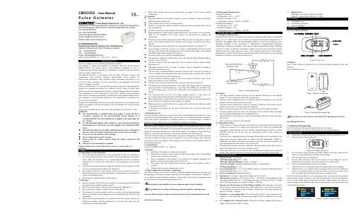
CMS50D2User ManualP u l s e O x i m e t e rContec Medical Systems Co., Ltd.Address:No.112 Qinhuang West Street, Economic &Technical Development Zone, Qinhuangdao, Hebei Province, PEOPLE’S REPUBLIC OF CHINA Tel: +86-335-8015430Fax: +86-335-8015588Technical support:+86-335-8015431E-mail:*****************.cnWebsite: EC REPRESENTATIVEShanghai International Holding Corp. GmbH(Europe)Address: Eiffestrasse 80, 20537, Hamburg, GermanyTel: +49-40-2513175Fax: +49-40-255726E-mail:*********************CMS2.782.294(CE)ESS/1.0 1.4.01.01.601 2019.11Instructions to UserDear Users, thank you very much for purchasing our product.This Manual is written and compiled in accordance with the council directive MDD93/42/EEC for medical devices and harmonized standards. In case of modifications and software upgrades, the information contained in this document is subject to change without notice.The Manual describes, in accordance with the Pulse Oximeter's features and requirements, main structure, functions, specifications, correct methods for transportation, installation, usage, operation, repair, maintenance and storage, etc. as well as the safety procedures to protect both the user and equipment. Refer to the respective chapters for details.Please read the Manual very carefully before using this equipment. These instructions describe the operating procedures to be followed strictly, failure to follow these instructions can cause measuring abnormality, equipment damage and personal injury. The manufacturer is NOT responsible for the safety, reliability and performance issues and any monitoring abnormality, personal injury and equipment damage due to user's negligence of the operation instructions. The manufacturer’s warranty service does not cover such faults.Owing to the forthcoming renovation, the specific products you received may not be totally in accordance with the description of this User Manual. We would sincerely regret for that.This product is medical device, and can be used repeatedly. Its using life is 3 years. WARNING:The uncomfortable or painful feeling may appear if using the device ceaselessly, especially for the microcirculation barrier patients. It is recommended that the sensor should not be applied to the same finger for over 2 hours.For the individual patients, there should be a more prudent inspecting in the placing process. The device can not be clipped on the edema and tender tissue.The light (the infrared is invisible) emitted from the device is harmful to the eyes, so the user and the maintenance man, can not stare at the light.Testee can not use enamel or other makeup.Testee’s fingernail can not be too long.Please peruse the relative content about the clinical restrictions and caution.This device is not intended for treatment.Caution: Federal law restricts this device to sale by or on the order of a physician.1 Safety1.1 Instructions for Safe OperationsCheck the main unit and all accessories periodically to make sure that there is no visible damage that may affect patient's safety and monitoring performance about cables and transducers. It is recommended that the device should be inspected once a week at least. When there is obvious damage, stop using the monitor.Necessary maintenance must be performed by qualified service engineers ONLY.Users are not permitted to maintain it by themselves.The oximeter cannot be used together with devices not specified in User's Manual.Only the accessory that appointed or recommendatory by manufacture can be used with this device.This product is calibrated before leaving factory.1.2 WarningsExplosive hazard—DO NOT use the oximeter in environment with inflammable gas such as some ignitable anesthetic agents.DO NOT use the oximeter while the testee measured by MRI and CT.The person who is allergic to rubber can not use this device.The disposal of scrap instrument and its accessories and packings(including battery, plastic bags, foams and paper boxes) should follow the local laws and regulations.Please check the packing before use to make sure the device and accessories are totally in accordance with the packing list, or else the device may have the possibility of working abnormally. Please don't measure this device with function test paper for the device's relatedinformation.1.3 AttentionsKeep the oximeter away from dust, vibration, corrosive substances, explosive materials,high temperature and moisture.If the oximeter gets wet, please stop operating it.When it is carried from cold environment to warm or humid environment, please do notuse it immediately.DO NOT operate keys on front panel with sharp materials.High temperature or high pressure steam disinfection of the oximeter is not permitted.Refer to User Manual in the relative chapter for instructions of cleaning anddisinfection.Do not have the oximeter immerged in liquid. When it needs cleaning, please wipe itssurface with medical alcohol by soft material. Do not spray any liquid on the devicedirectly.When cleaning the device with water, the temperature should be lower than 60 ℃.As to the fingers which are too thin or too cold, it would probably affect the normalmeasure of the patients' SpO and pulse rate, please clip the thick finger such as thumband middle finger deeply enough into the probe.Do not use the device on infant or neonatal patients.The product is suitable for children above four years old and adults (Weight should bebetween 15 kg to 110 kg).The device may not work for all patients. If you are unable to achieve stable readings,discontinue use.The update period of data is less than 5 seconds, which is changeable according todifferent individual pulse rate.The waveform is normalized.Please read the measured value when the waveform onscreen is equably and steady-going, Here this measured value is optimal value. And thewaveform at the moment is the standard one.If some abnormal conditions appear on the screen during test process, pull out thefinger and reinsert to restore normal use.The device has normal useful life for three years since the first electrified use.The hanging rope attached the product is made from Non- allergy material, if particulargroup are sensitive to the hanging rope, stop using it. In addition, pay attention to theuse of the hanging rope , do not wear it around the neck avoiding cause harm to thepatient.The instrument dose not have low-voltage prompt function, it only shows thelow-voltage.please change the battery when the battery energy is used out.When the parameter is particularly, The instrument dose not have prompt function.Donot use the device in situations where prompts are required.Batteries must be removed if the device is going to be stored for more than one month,or else batteries may leak.A flexible circuit connects the two parts of the device. Do not twist or pull on theconnection.1.4 Indication for UseThe Fingertip Pulse Oximeter is a non-invasive device intended for the spot-check of oxygensaturation of arterial hemoglobin (SpO) and the pulse rate of adult and pediatric patients inhome and hospital environments (including clinical use in internist/surgery, anesthesia,intensive care ect.). This device is not intended for continuous monitoring.2 OverviewThe pulse oxygen saturation is the percentage of HbO in the total Hb in the blood, so-calledthe O concentration in the blood. It is an important bio-parameter for the respiration. For thepurpose of measuring the SpO more easily and accurately, our company developed the PulseOximeter. At the same time, the device can measure the pulse rate simultaneously.The Pulse Oximeter features in small volume, low power consumption, convenient operationand being portable. It is only necessary for patient to put one of his fingers into a fingertipphotoelectric sensor for diagnosis, and a display screen will directly show measured value ofHemoglobin Saturation.2.1 ClassificationClass II b, (MDD93/42/EEC IX Rule 10)2.2 FeaturesOperation of the product is simple and convenient.The product is small in volume, light in weight (total weight is about 50g includingbatteries) and convenient in carrying.Power consumption of the product is low and the two originally equipped AAAbatteries can be operated continuously for 20 hours.The product will enter standby mode when no signal is in the product within 5seconds.Display direction can be changed,easy to view.2.3 Major Applications and Scope of ApplicationThe Pulse Oximeter can be used to measure human Hemoglobin Saturation and pulse ratethrough finger, and indicate the pulse intensity by the bar-display. The product is suitable foruse in family, hospital (Ordinary sickroom), Oxygen Bar, social medical organizations andalso the measure of saturation oxygen and pulse rate.The product is not suitable for use in continuous supervision for patients.The problem of overrating would emerge when the patient is suffering fromtoxicosis which caused by carbon monoxide, the device is not recommended to be usedunder this circumstance.2.4 Environment RequirementsStorage Environmenta) Temperature: -40 ℃ ~ +60 ℃b) Relative humidity: ≤95%c) Atmospheric pressure: 500 hPa ~ 1060 hPaOperating Environmenta) Temperature: 10 ℃ ~ 40 ℃b) Relative Humidity: ≤75%c) Atmospheric pressure: 700 hPa ~ 1060 hPa3.1 Principle of MeasurementPrinciple of the Oximeter is as follows: An experience formula of data process is establishedtaking use of Lambert Beer Law according to Spectrum Absorption Characteristics ofReductive Hemoglobin (Hb) and Oxyhemoglobin (HbO) in glow & near-infrared zones.Operation principle of the instrument is: Photoelectric Oxyhemoglobin InspectionTechnology is adopted in accordance with Capacity Pulse Scanning & Recording Technology,so that two beams of different wavelength of lights can be focused onto human nail tipthrough perspective clamp finger-type sensor. Then measured signal can be obtainedby aphotosensitive element, information acquired through which will be shown on screen throughtreatment in electronic circuits and microprocessor.Figure 1 Operating principle3.2 Caution1.The finger should be placed properly (see the attached illustration of this manual,Figure 5), or else it may cause inaccurate measurement.2.The SpO sensor and photoelectric receiving tube should be arranged in a way with thesubject’s arteriole in a position there between.3.The SpO sensor should not be used at a location or limb tied with arterial canal orblood pressure cuff or receiving intravenous injection.4.Make sure the optical path is free from any optical obstacles like rubberized fabric.5.Excessive ambient light may affect the measuring result. It includes fluorescent lamp,dual ruby light, infrared heater, direct sunlight and etc.6.Strenuous action of the subject or extreme electrosurgical interference may also affectthe accuracy.7.Testee can not use enamel or other makeup.3.3 Clinical Restrictions1.As the measure is taken on the basis of arteriole pulse, substantial pulsating blood flowof subject is required. For a subject with weak pulse due to shock, low ambient/bodytemperature, major bleeding, or use of vascular contracting drug, the SpO waveform(PLETH) will decrease. In this case, the measurement will be more sensitive tointerference.2.For those with a substantial amount of staining dilution drug (such as methylene blue,indigo green and acid indigo blue), or carbon monoxide hemoglobin (COHb), ormethionine (Me+Hb) or thiosalicylic hemoglobin, and some with icterus problem, theSpO determination by this monitor may be inaccurate.3.The drugs like dopamine, procaine, prilocaine, lidocaine and butacaine may also be amajor factor blamed for serious error of SpO measure.4.As the SpO value serves as a reference value for judgement of anemic anoxia and toxicanoxia, some patients with serious anemia may also report good SpO measurement.1)Display Format: LCD Display;SpO Measuring Range: 0% ~ 100%;Pulse Rate Measuring Range: 30 bpm ~ 250 bpm;Pulse Wave Display: columniation display and the waveform display.PI Measuring Range: 0 ~ 20%2)Power Requirements: 2×1.5 V AAA alkaline battery (or using the rechargeable batteryinstead),adaptable range: 2.6 V - 3.6 V.3)Power Consumption: Smaller than 80 mA.4)Resolution: 1% for SpO, 1 bpm for Pulse Rate and 0.1% for PI.5)Measurement Accuracy: ±2% in stage of 70% ~ 100% SpO, and meaningless whenstage being smaller than 70%. ±2 bpm during the pulse rate range of 30 bpm ~ 99 bpmand ±2% during the pulse rate range of 100 bpm ~ 250 bpm .6)Measurement Performance in Weak Filling Condition: SpO and pulse rate can beshown correctly when pulse-filling ratio is 0.4%. SpO error is ±4%, pulse rate error is± 2 bpm during the pulse rate range of 30 bpm ~ 99 bpm and ±2% during the pulse raterange of 100 bpm ~ 250 bpm .7)Resistance to surrounding light:The deviation between the value measured in thecondition of man-made light or indoor natural light and that of darkroom is less than±1%.8)It is equipped with a function switch: The product will enter standby mode when nosignal is in the product within 5 seconds.9)Optical SensorRed light (wavelength is 660 nm, 6.65 mW)Infrared (wavelength is 880 nm, 6.75 mW)One hanging ropeTwo batteries(optional)One User Manual6 Installation6.1 View of the Front PanelFigure 3 Batteries installationPlease take care when you insert the batteries for the improper insertionmay damage the device.6.3 Mounting the Hanging RopeStep 1. Put the end of the rope through the hole refer to Figure 3 .Step 2. Put another end of the rope through the first one and then tighten it.7 Operating Guide1)Insert the two batteries properly to the direction, and then replace the cover.2)Open the clip as shown in Figure 5.Figure 5 Put finger in position3)Let the patient’s finger put into the rubber cushions of the clip (make sure thefinger is in the right position), and then clip the finger.4)Press the button once on front panel.5)Do not shake the fingerand keep the patient at ease duringthe process.Meanwhile, human body is not recommended in movement status.6)Get the information directly from screen display.When the device is in operation status, the display mode can be changed.7)When the device is in standby mode, pressing the button can exit it; When the device is in operation status, pressing the button can enter into menus; In the state of prompt, press the button long can pause prompt for 60s.Press the button when the device is in operation status, can enter into menus(in the Figure6,Figure7,Figure 8 ,Figure 9, press the button shortly can move the drop-down icon, press the button long can turn on/off the pulse sound prompt, enter the next menu to change the up and down limit of pulse rate and SpO, and select the direction of the up and down limit.)Figure 6 Menu interface Figure 7 prompt setting interfaceFigure 8 PR prompt limits setting interface Figure 9 SpO prompt limits setting interfaceFingernails and the luminescent tube should be on the same side.Please change the batteries when the low-voltage displayed on the screen. Please clean the surface of the device before using. Wipe the device withmedical alcohol first, and then let it dry in air or clean it by dry clean fabric. Using the medical alcohol to disinfect the product after use, prevent fromcross infectio n for next time use.Please take out the batteries if the oximeter is not in use for a long time.The best storage environment of the device is -40 ºC to 60 ºC ambienttemperature and not higher than 95% relative humidity.Users are advised to calibrate the device termly (or according to thecalibrating program of hospital). It also can be performed at the state-appointed agent or just contact us for calibration. High-pressure sterilization cannot be used on the device. Do not immerse the device in liquid.It is recommended that the device should be kept in a dry environment.Humidity may reduce the useful life of the device, or even damage it.Trouble Possible ReasonSolutionThe SpOand Pulse Rate can not be displayed normally 1. The finger is not properly positioned.2. The patient’s SpO is too low to be detected. 1. Place the finger properly and try again.2. Try again; Go to a hospital for a diagnosis if you are sure the device works allright.The SpO and Pulse Rate are not displayed stably1. The finger is not placed inside deep enough.2. The finger is shaking or the patient is moving. 1. Place the finger properly and try again.2. Let the patient keep calm The device can not be turned on1. The batteries are drained or almost drained.2. The batteries are not inserted properly.3. The malfunction of the device.1. Change batteries.2. Reinstall batteries.3. Please contact the local service center.The display is off suddenly 1. The product will enter standby mode when no signal is in the product within 5 seconds2. The batteries are almost drained.1. Normal.2. Change batteries.SymbolDescriptionType BFRefer to instruction manual/bookletThe battery voltage indication is deficient (change the battery in time avoiding the inexact measure)1.No finger inserted2.An indicator of signal inadequacyBattery positive electrodeBattery cathode1.Exit standby mode.2.Can enter into menus. SNSerial numberPrompt inhibitWEEE (2002/96/EC)IP22International ProtectionThis item is compliant with Medical Device Directive 93/42/EEC of June 14, 1993, a directive of the European Economic Community.Manufacture DateStorage and Transport Temperature limitationStorage and Transport Humidity limitationStorage and Transport Atmospheric pressure limitationThis side upFragile, handle with careKeep dryRecyclableDisplay InformationDisplay Mode The Pulse Oxygen Saturation (SpO ) LCD Pulse Rate (PR) LCD Perfusion Index (PI) LCD display Pulse Intensity (bar-graph) LCD bar-graph display Pulse waveLCDSpO Parameter Specification Measuring range 0% ~ 100%, (the resolution is 1%). Accuracy70% ~ 100%: ±2%, Below 70% unspecified. Optical SensorRed light (wavelength is 660 nm) Infrared (wavelength is 880 nm)Pulse Parameter Specification Measuring range 30 bpm ~ 250 bpm (the resolution is 1 bpm) Accuracy ±2 bpm or ±2% select largerPulse Intensity RangeContinuous bar-graph display, the higher display indicate the stronger pulse.Battery Requirement1.5 V (AAA size) alkaline batteries × 2 or rechargeable battery Battery Useful LifeTwo batteries can work continually for 20 hours Dimensions and Weight Dimensions 60(L) × 30.5(W) × 32.5(H) mm WeightAbout 50 g (with the batteries)Appendix1Guidance and manufacture’s declaration-electromagnetic emissionfor all EQUIPMENT and SYSTEMSGuidance and manufacture’s declaration –electromagnetic emission The CMS50D2 Pulse Oximeter is tended for use in the electromagnetic environment specified below. The customer of the user of the CMS50D2 Pulse Oximeter should assure that it isused in such an environment. Emission test Compliance Electromagnetic environment-guidance RF emissions CISPR 11 Group 1The CMS50D2 Pulse Oximeter uses RF energy only for their internal function. Therefore, its RF emissions are very low and are not likely to cause any interference in nearby electronic equipment.RF emissions CISPR 11Class B The CMS50D2 Pulse Oximeter is suitable for use in all establishments, including domestic establishments and those directly connected to the public low-voltage power supply network that supplies buildings used for domestic purposes.Harmonic emissionsIEC 61000-3-2 Not applicableV oltage fluctuations/ flicker emission IEC 61000-3-3Not applicableGuidance and manufacture’s declaration-electromagnetic immunityfor all EQUIPMENT and SYSTEMSGuidance and manufacture’s declaration-electromagnetic immunityThe CMS50D2 Pulse Oximeter is intended for use in the electromagnetic environment specified specified below. The the user of CMS50D2 Pulse Oximeter should assure that it is used in such an environment. Immunity testIEC60601 test levelCompliance levelElectromagneticenvironment -guidanceElectrostaticdischarge(ESD) IEC 61000-4-2±6KV contact ±8KV air ±6KV contact ±8KV air Floors should be wood, concrete or ceramic tile. Iffloor are covered withsynthetic material, the relative humidity should be at least 30%. Power frequency (50Hz)magnetic field IEC 61000-4-8 3A/m3A/mPower frequency magnetic fields should be at levels characteristic of a typical location in a typical commercial or hospital environmentGuidance and manufacture’s declaration-electromagnetic immunitytransmitters, as determined by an electromagnetic site survey, a should be less than the compliance level in each frequency range.bInterference may occur in the vicinity of equipment marked with the following symbol:NOTE 1 At 80MHz and 800MHz, the higher frequency range applies. NOTE 2 These guidelines may not apply in all situations. Electromagneticpropagation is affected by absorption and reflection from structures, objects and people.a. Field strengths from fixed transmitters, such as base stations for radio (cellular/cordless) telephones and land mobile radios, amateur radio, AM and FM radio broadcast and TV broadcastcannot be predicted theoretically with accuracy. To assess the electromagnetic environment due to fixed RF transmitters, an electromagnetic site survey should be considered. If the measured field strength in the location in which The CMS50D2 Pulse Oximeter is used exceeds the applicable RF compliance level above, the CMS50D2 Pulse Oximeter should be observed to verify normal operation. If abnormal performance is observed, additional measures may be necessary, such as reorienting or relocating the CMS50D2 Pulse Oximeter.b. Over the frequency range 150 KHz to 80 MHz, field strengths should be less than 3V/m.Recommended separation distances between portable and mobile RF communications equipment and the EQUIPMENT or SYSTEMAppendix 2StatePrompt condition delay Prompt signal generation delay Low voltage prompt 60s 5ms SpO prompt 1s 5ms Pulse rate prompt 1s 5ms Finger out prompt 16ms5ms。
高铁酸钾降解苯并芘的荧光光谱研究

本课题组在前期 高铁 酸钾 的制备方 面已经进行 了大量试 验, 分别运用 电解法 、次氯酸盐氧 化法制 备了一 系列高铁 酸
钾 ;同时 , 利用制备 出的高纯度 、较 高产率及稳 定性 较好 的
高铁酸钾 , 考察其在处理不 同来源污水水体 中各类污染物 的 去除或降解 情况 , 中包括选择 以 I P为处理对象 ,初步 获 其 M
程 :n F / 一0 5 32+0 1 12 R = O 942 ,由此 推 测 高 铁 酸 钾 与 I P的 反 应 过 程 符 合 一 级 反 应 动 I( o F ) . 6 t . 7 ,( . 9 ) M
力学规律 。为研究 高铁 酸钾 降解其他污染物反应过程的机理提供 了十分有益的参 考。
(E , E M) 时间扫描及荧光光度定量等多种荧光光谱 分析方 法所提供 的多角度 的荧光光 谱信息 ,揭示 了 I P M 分子在降解过程 中浓度随时问变化规 律 , 尤其高铁酸钾与 I P作用过 程 的动力 学特征 。同步荧 光和 三维荧 M 光 光谱共 同揭示 出, 高铁酸钾在 2 内能降解 9 的 I P 6 以后反应趋于缓慢的变化规律 ;由时间扫描 0S 1 M , 0S 荧光光谱结合发射和 同步两种荧光光度定 量方 法 , 便捷地获得 了高铁酸钾 与 I P的反应过 程 中的动力 学方 M
种绿色 、 高效的新型水处理剂 , 兼具氧化 、 絮凝 、 灭菌 、 消
毒、 除臭等多种功能 。因此 , 在围绕关于高铁 酸钾 的高纯 度、
高产 率 、 稳定性好的合成与制备 、 表征『 ] 1 、以及在应用于去 除或降解含有各类污染物 、 尤其在处理各种污染程 度的不 同 背景来 源水体的综合效果 、 反应机理 、反应 动力学过 程探讨 等方面的研究均受到 了广泛的关注[1 。 73 ] 多环 芳 烃 ( AHs 是一 类 典 型 的 持 久 性 有 机 污 染 物 P ) ( O s, P P ) 具有强烈 的亲脂 憎水性 及较 高的辛 醇 一水分 配 系 数, 其特殊 的环状结 构很难被 降解 ,因此 ,易于在不 同环境 中不断积累和放 大。苯并 [ ] ( P 作 为 P a芘 I ) M AHs 的典 型代 表, 其来源 与分 布均 较为广泛 , 结构 上 由 5 个苯 环组 成 , 是
‘无核白’葡萄及其营养变异系的光合作用与果实特性(英文)

摘
要 : ‘ 核白 ’ 萄为对 照 , 以 无 葡 以其 自然 营 养 变 异 系 ‘ 穗 无 核 白 ’ ‘ 粒 无 核 白 ’ ‘ 粒 无 核 白 ’ ‘ 3 与 ‘ 7 长 、长 、大 、W ’ w ’
为 材料 , 新 疆 吐 鲁 番 部善 田 间栽 培 条 件 下 比较 其 果 实 及 光 合 作 用 特 性 , ‘ 核 白 ’ 列 葡 萄 优 良 品 种 选 育 提 供 在 为 无 系
依 据 。结 果 表 明 :1 供试 各 营 养 系 具 有 较 高 的 光 、 利 用 能 力 , 片 日平 均 净 光 合 速 率 (. 2 ~ 74 23/ l () 热 叶 5 5 77 . 1 , mo ・ m ・ ) 大 于 对 照 (. 7  ̄ l・T ・ - ) 除 ‘ 穗 无 核 白 ’ , 余 营 养 系 均 无 明 显 光 合 ‘ 休 ’ 象 。 s 均 48 97/ mo 1 I 81 ; 长 外 其 午 现 ( ) 试 条 件 下 净 光 合 速 率 与 田 间 空 气 温 度 、 片 温 度 、 片 表 面 蒸 汽 压 差 呈 正 相 关 ; 气 孔 导 度 、 照 强 度 等 因 子 2供 叶 叶 而 光 是 ‘ 核 白 ’ 列 葡 萄 光 合 作 用 的 非 决 定 因素 。 () 长 穗 无 核 白 ’ 无 系 3‘ 的穗 长 ( 6 4 m) 对 照 ( 5 2 m) 1 4 倍 ; 3 . 3c 是 2 . 7c 的 . 4 各 营养 系果 粒 均 大 于 对 照 , 中 ‘ 、 大 粒 无 核 白 ’ ‘ 穗 无 核 白 ’ ‘ 粒 无 核 白 果 粒 ( . 9 、 . 0 、 其 W3 ‘ 、长 、长 2 0 60 2 2 2 7 2 0 93 14 03g 极 显 著 大 于 对 照 ( . 5 ) () 长 粒 无 核 白 ’ 粒 耐 压 力 和果 梗 耐 拉 力 均 极 显 著 优 于 对 照 , . 1 、. 7 ) 1 0 77g 。 4 ‘ 果 其 他 营 养 系 与对 照无 显 著 差 异 ; 粒 较 大 的 ‘ 3 、 大 粒 无 核 白 ’ ‘ 粒 无 核 自 ’ 可 溶 性 固 形 物 含 量 ( 2 9 、 果 W ’‘ 、长 等 2. 2 2 . 7 、3 1 ) 对 照 (3 8 ) 差 异 。综 合 分 析 认 为 , 试 营 养 系 ‘ 3 、w 7 和 ‘ 粒无 核 白 ’ 对 较 优 良 , 3 5 2 . 7 与 2. 5 无 供 W ’‘ ’ 长 相 宜 进 一 步研 究 ; 究 证 明果 实 与 叶 片光 合 作 用 特性 指 标 可 用 于 葡 萄 营 养 系选 种 。 研
欧盟修订酒精饮料分析的参考方法

pig bone collagen peptide Gcalcium chelate using response surface methodology and its structural characterization and stabilityanalysis[J].Food Chemistry,2019,284:80G89.[13]LIU B T,ZHUANG Y L,SUN L P.Identification andcharacterization of the peptides with calcium Gbinding capacity from tilapia (Oreochromis niloticus )skin gelatin enzymatic hydrolysates[J].Journal of Food Science,2020,85(1):114G122.[14]WU H C,CHEN H M,SHIAU C Y.Free amino acids and peptidesas related to antioxidant properties in protein hydrolysates of mackerel (Scomber austriasicus )[J].Food Research International,2003,36(9):949G957.[15]ZHANG Y F ,XIU D,ZHUANG Y L.Purification and characterizationof novel antioxidant peptides from enzymatic hydrolysates of tilapia (Oreochromis niloticus )skin gelatin[J].Peptides,2012,38(1):13G21.[16]AKINYED A I,FAGBEMI T N,OSUNDAHUNSI O F,et al.Amino acid composition and antioxidant properties of the enzymatic hydrolysate of calabash nutmeg (Monodora myristica )and its membrane ultrafiltration peptide fractions [J].Journal of Food Biochemistry,2020,45(8):e13437.[17]龙芳.汉麻肽钙螯合物的制备及其结构表征和稳定性[J].中国油脂,2021,46(9):33G39.LONG F.Preparation of hemp peptide Gcalcium chelate and its structural characterization and stability properties [J].China Oils and Fats,2021,46(9):33G39.[18]JIANG Z,YU G,BAO Q,et al.Macrophage Gstimulating activities of a novel low molecular weight saccharide fragment prepared from ascophyllan with alginate lyase [J].Journal of Functional Foods,2020,67:103839.[19]HOU H,WANG S,ZHU X,et al.A novel calcium Gbinding peptide from Antarctic krill protein hydrolysates and identification of binding sites of calcium Gpeptide complex [J ].Food Chemistry,2018,243:389G395.[20]张凯,侯虎,彭喆,等.鳕鱼骨明胶多肽螯合钙制备工艺及其在体外模拟消化液中的稳定性[J].食品科学,2016,37(24):1G7.ZHANG K,HOU H,PENG Z,et al.Optimization of preparation of calcium Gchelated cod bone gelatin peptide and its stability in simulated gastrointestinal system[J].Food Science,2016,37(24):1G7.[21]富天昕,张舒,盛亚男,等.绿豆多肽锌螯合物的制备及其结构与体外消化的分析[J].食品科学,2020,41(4):59G65.FU T X,ZHANG S,SHENG Y N,et al.Preparation,structure and in vitro digestion analysis of mung bean polypeptide zinc chelate [J].Food Science,2020,41(4):59G65.[22]BETTS H D,NEVILLE S L,MCDEVITT C A,et al.Thebiochemical fate ofAg +ionsinstaphylococcus aureus ,Escherichia coli ,and biological media [J].Journal of Inorganic Biochemistry,2021,225:111598.[23]覃宇,鞠守勇.鱼鳞多肽亚铁螯合物的制备及结构表征[J].西南农业学报,2020,33(2):456G463.QIN Y ,JU S Y.Preparation and structural characterization of scale polypeptide ferrous chelate [J ].Southwest Agricultural Journal,2020,33(2):456G463.[24]WANG X,GAO A,CHEN Y ,et al.Preparation of cucumber seedpeptide Gcalcium chelate by liquid state fermentation and its characterization[J].Food Chemistry,2017,229:487G494.[25]钱跃威,徐瀚麟,吕奇晏,等.鳗鱼骨胶原肽钙螯合物的制备及其稳定性和Caco G2吸收特性[J].食品科学,2020,41(24):1G8.QIAN Y W,XU H L,LU Q Y ,et al.Preparation,stability and Caco G2absorption characteristics of calcium chelate of eel collagen peptide[J].Food Science,2020,41(24):1G8.[26]MANNINI B,HABCHI J,CHIA S,et al.Stabilization andcharacterization of cytotoxic A β40oligomers isolated from anaggregation reaction in the presence of zinc ions[J].ACS Chemical Neuroscience,2018,9(12):2959G2971.[27]陈皓,柯晨,张梓凯.钙离子浓度对脂肪干细胞增殖和成肌分化的影响[J].现代生物医学进展,2022,22(7):1206G1210.CHEN H,KE C,ZHANG Z K.Effects of calcium concentration on proliferation and myogenic differentiation of adipose stem cells[J].Progress in Modern Biomedicine,2022,22(7):1206G1210.44基础研究F U N D AM E N T A LR E S E A R C H 总第256期|2023年2月|Copyright ©博看网. All Rights Reserved.。
饥饿熊蜂的催花绝技--啃咬植物叶片促其提前开花

2020年40月蜂业硏究|只。
国外养蜂科技2饥饿熊蜂的催花绝技—啃咬植物叶片促其提前开花赵慧月丨译安建东I校中国农业科学院蜜蜂研究所,北京100093近日,苏黎世联邦理工学院和法国农科院等单位合作在《科学(Science)》上发表论文,表明在花粉资源匮乏情况下,熊蜂会破坏未开花植物的叶片使其提前开花,而在花粉充足条件下这种行为大大减少。
这种行为在商业化熊蜂和野生熊蜂中均存在,可能是熊蜂促使植物开花的一种适应性策略,熊蜂和植物的这种互作可能具有重要的生态学意义。
开花植物和传粉者通过长期协同进化,形成了相互匹配的发育周期。
由于全球气候持续变暖,这种相互匹配的物候关系受到干扰。
早春时节,越冬后的熊蜂蜂王开始重建蜂群,此时迫切需要花粉,而花粉资源缺乏将对熊蜂发育造成严重威胁。
研究发现,熊蜂工蜂有啃咬植物叶片的行为,但它却不以为叶片为食物,也不带其回蜂巢。
因此研究者针对熊蜂损伤植物叶片是否会影响植物开花这个问题设置了如下实验:以未开花番茄和黑芥为材料,分别设计地熊蜂损伤、类似机械损伤和无损伤3组处理;在实验室环境下分别给予熊蜂充足花粉或完全不给花粉,数天后进行处理的替换。
结果表明,在番茄中,熊蜂损伤组的开花时间比无损伤组提前了30天,比机械损伤组提前了25天;在黑芥中,熊蜂损伤组的开花时间分别提前了16天和8天;无论给予花粉的顺序如何,在花粉缺乏条件下,熊蜂损伤植物叶片行为的发生率都显著升高。
这表明熊蜂损伤叶片的行为受到可利用花粉资源的影响,并可以促使植物提前开花。
当熊蜂可以选择到更远的地方觅食时,是否仍会损伤附近的未开花植物呢?为探明这个问题,在2018-2019年,研究者在半野生环境中设置未开花植物实验,在其附近添加或移除可利用花卉,观察未开花植物在两种条件下被熊蜂损伤的情况。
结果当花粉资源匮乏时,熊蜂会用喙和下额在植物叶片上咬洞发现,当附近无花卉资源时,熊蜂损伤植物叶片的程度很高;当附近给予其可利用花卉资源时,熊蜂对未开花植物的伤害则大幅减少,而移除可利用花卉后,熊蜂对未开花植物的损害程度又显著提高,这证明花粉资源充足时会减少熊蜂对植物叶片的损伤行为。
有机化学实验中关于过柱的实验方法和技巧
关于过柱的实验方法和技巧(注意:有机溶剂对身体特有害别是心肺;肝脏等所有过柱操作都要在通风橱里进行!!常说的过柱子应该叫柱层析分离,也叫柱色谱。
我们常用的是以硅胶或氧化铝作固定相的吸附柱。
由于柱分的经验成分太多,所以下面我就几年来过柱的体会写些心得,希望能有所帮助。
1、柱子可以分为:加压,常压,减压压力可以增加淋洗剂的流动速度,减少产品收集的时间,但是会减低柱子的塔板数。
所以其他条件相同的时候,常压柱是效率最高的,但是时间也最长,比如天然化合物的分离,一个柱子几个月也是有的。
减压柱能够减少硅胶的使用量,感觉能够节省一半甚至更多,但是由于大量的空气通过硅胶会使溶剂挥发(有时在柱子外面有水汽凝结),以及有些比较易分解的东西可能得不到,而且还必须同时使用水泵抽气(很大的噪音,而且时间长)。
以前曾经大量的过减压柱,对它有比较深厚的感情,但是自从尝试了加压后,就几乎再也没动过减压的念头了。
加压柱是一种比较好的方法,与常压柱类似,只不过外加压力使淋洗剂走的快些。
压力的提供可以是压缩空气,双连球或者小气泵(给鱼缸供气的就行)。
特别是在容易分解的样品的分离中适用。
压力不可过大,不然溶剂走的太快就会减低分离效果。
个人觉得加压柱在普通的有机化合物的分离中是比较适用的。
2、关于柱子的尺寸,应该是粗长的最好柱子长了,相应的塔板数就高。
柱子粗了,上样后样品的原点就小(反映在柱子上就是样品层比较薄),这样相对的减小了分离的难度。
试想如果柱子十厘米,而样品就有二厘米,那么分离的难度可想而知,恐怕要用很低极性的溶剂慢慢冲了。
而如果样品层只有厘米,那么各组分就比较容易得到完全分离了。
当然采用粗大的柱子要牺牲比较多的硅胶和溶剂了,不过这些成本相对于产品来说也许就不算什么了(有些不环保的说,不过溶剂回收重蒸后也就减小了部分浪费)。
现在见到的柱子径高比一般在1:5~10,书中写硅胶量是样品量的30~40倍,具体的选择要具体分析。
如果所需组分和杂质分的比较开(是指在所需组分rf 在~,杂质相差以上),就可以少用硅胶,用小柱子(例如200毫克的样品,用2cm×20cm的柱子);如果相差不到,就要加大柱子,我觉得可以增加柱子的直径,比如用3cm的,也可以减小淋洗剂的极性等等。
国际上著名的从事药剂学研究的专家

Intra Oral Delivery (口腔内传递)直接由口腔黏膜吸收,瞬间进入血液循环,有效成分不流失。
Universities, Departments,FacultiesResearchersButler University College of Pharmacy and Health Sciences Health Sciences USA Associate Professor Nandita G. DasMain focus on her research facilities are about peformulation, biopharmaceutics, drug targeting, anticancer drug delivery.Purdue University School of Pharmacy and Pharmacal Sciences Department of Industrial and Physical Pharmacy (IPPH) USA Professor Kinam ParkControlled Drug Delivery, Glucose-Sensitive Hydrogels for Self-Regulated Insulin Delivery, Superporous Hydrogel Composites, Oral Vaccination using Hydrogel Microparticles, Fractal Analysis of Pharmaceutical Solid Materials.St. John's University School of Pharmacy and Allied Health ProfessionsUSA Professor Parshotam L. MadanControlled and targeted drug delivery systems; Bio-erodible polymers as drug delivery systemsThe University of Iowa College of Dentistry Department of Oral Pathology, Radiology, and Medicine USA Professor Christopher A. Squierpermeability of skin, and oral mucosa to exogenous substances, including alcohol and tobacco, and drug deliveryThe University of Iowa College of Pharmacy Department of Pharmaceutics USA Associate Professor Maureen D. DonovanMucosal drug delivery especially via the nasal, gastrointestinal and vaginal epithelia; and mechanisms of drug absorption and disposition.The University of Texas at San Antonio College of Engineering Department of Biomedical Engineering USA Professor Jeffrey Y. ThompsonDental restorative materials and implantsThe University of Utah Pharmaceutics & Pharmaceutical Chemistry USA Professor John W. MaugerDr. Maugner is mainly focused on dissolution testing and coating technology of orally administered drug products with bitter taste about which he is one of the inventors of a filed patent.University of Kentucky College of Pharmacy Pharmaceutical Sciences USA Professor Peter CrooksDr. Crooks is internationally known for his research work in drug discovery, delivery, and development, which includes drug design and synthesis, pharmacophore development, drug biotransformation studies, prodrug design, and medicinal plant natural product research. His research also focuses on preclinical drug development, including drug metabolism and pharmacokinetics in animal models, dosage form development, and drug delivery assessment using both conventional and non-conventional routes, and preformulation/formulation studies.Associate Professor Russell MumperDr. Mumper's main research areas are thin-films and mucoadhesive gels for (trans)mucosal delivery of drugs, microbicides, and mucosal vaccines, and nanotemplate engineering of nano-based detection devices and cell-specific nanoparticles for tumor and brain targeting, gene therapy and vaccines.West Virginia University School of Pharmacy Department of Basic Pharmaceutical Sciences USA Associate Professor Paula Jo Meyer StoutDr. Stout's research areas are composed of dispersed pharmaceutical systems, sterile product formulation DDS for dental diseases and coating of sustained release formulations.Monash University Victorian College of Pharmacy Department of Pharmaceutics Australia Professor Barrie C. FinninTransdermal Drug Delivery. Physicochemical Characterisation of Drug Candidates. Topical Drug Delivery. Drug uptake by the buccal mucosaProfessor Barry L. ReedTransdermal Drug Delivery. Topical Drug Delivery. Formulation of Dental Pharmaceuticals.University of Gent Faculty of Pharmaceutical Sciences Department of Pharmaceutics Belgium Professor Chris Vervaet-Extrusion/spheronisation - Bioadhesion - Controlled release based on hot stage extrusion technology - Freeze-drying - Tabletting and - GranulationPh.D. Els AdriaensMucosal drug delivery (Vaginal and ocular) Nasal BioadhesionUniversity of Gent Faculty of Pharmaceutical SciencesLaboratory of Pharmaceutical Technology Belgium Professor Jean Paul Remonbioadhesive carriers, mucosal delivery, Ocular bioerodible minitablets, Compaction of enteric-coated pellets; matrix-in-cylinder system for sustained drug delivery; formulation of solid dosage forms; In-line monitoring of a pharmaceutical blending process using FT-Raman spectroscopy; hot-melt extruded mini-matricesDanish University of Pharmaceutical Sciences Department of Pharmaceutics Denmark Associate Professor Jette JacobsenLow soluble drugs ?in vitro lymphatic absorption Drug delivery to the oral cavity ?in vitro models (cell culture, diffusion chamber) for permeatbility and toxicity of drugs, in vivo human perfusion model, different formulation approaces, e.g. iontophoresis.。
- 1、下载文档前请自行甄别文档内容的完整性,平台不提供额外的编辑、内容补充、找答案等附加服务。
- 2、"仅部分预览"的文档,不可在线预览部分如存在完整性等问题,可反馈申请退款(可完整预览的文档不适用该条件!)。
- 3、如文档侵犯您的权益,请联系客服反馈,我们会尽快为您处理(人工客服工作时间:9:00-18:30)。
a r X i v :a s t r o -p h /9812171v 1 9 D e c 19981ISOPHOT OBSER V ATIONS OF COMET HALE-BOPP:INITIAL DATA REDUCTION∗E.Gr¨u n 1,S.B.Peschke 1,M.Stickel 2,T.M¨u ller 2,3,H.Kr¨u ger 1,H.B¨o hnhardt 4,T.Y.Brooke 2,H.Campins 6,J.Crovisier 7,M.S.Hanner 5,I.Heinrichsen 3,H.U.Keller 8,R.Knacke 9,my 10,Ch.Leinert 2,D.Lemke 2,C.M.Lisse 11,M.M¨u ller 1,12,D.J.Osip 6,M.Solc 13,M.Sykes 14,V.Vanysek 13,+and J.Zarnecki 151Max-Planck-Institut f¨u r Kernphysik,Heidelberg,Germany 2Max-Planck-Institut f¨u r Astronomie,Heidelberg,Germany3ISO Data Center,ESA,Villafranca,Spain 4European Southern Observatory,Santiago,Chile 5Jet Propulsion Laboratory,Pasadena,USA 6University of Florida,Gainesville,USA 7Observatoire de Paris,Meudon,France8Max-Planck-Institut f¨u r Aeronomie,Katlenburg-Lindau,Germany9Penn State University,Erie,USA10Laboratoire d’astrophysique spatial,Marseille,France 11University of Maryland,College Park,USA 12ESA-ESOC,Darmstadt,Germany 13Charles University,Prague,Czech Republic 14University of Arizona,Tucson,USA 15University of Kent,Canterbury,UK+deceasedABSTRACTComet Hale-Bopp was observed five times with ISOPHOT,the photometer on board the Infrared Space Observatory (ISO).Each time broadband pho-tometry was performed using 4different detectors,5apertures and,10filters covering the range between 3.6to 175µm.Calibration measurements using the internal Fine Calibration Source were done together with each individual measurement.Background ob-servations were performed with identical instrument settings at the same positions on the sky several days after the comet observations.The observation strat-egy and the initial data reduction steps are described in some detail and the resulting in-band power values of the Hale-Bopp observations and their uncertainties are derived.Initial reduction of these measurements was performed in 3steps:(1)processing of raw data by removing instrumental and energetic particle ef-fects,(2)averaging of the individual signals,and (3)determination of the detector responsivities and their uncertainties.The detector signal is determined by two different methods and the best value is chosen.At the present level of processing uncertainties range from 10%to a factor of 3for the low power levels at short wavelengths.The in-band power levels at dif-ferent wavelengths varied over 3orders of magnitude.2First,a raw selection based on the IRAS all-sky sur-vey(ISSA)plates was performed.’Dark regions’at 12,25,60and100µm along the cometary track on the ISSA plates were selected.Second,the selected regions were examined with IRSKY(IPAC)to assure that no known point sources were within5arcmin of the cometary track,and no prominent(cirrus)struc-tures were visible on the100µm ISSA plates.Also the background estimates for eachfilter of the ISO observations were derived with IRSKY.Background subtraction is crucial for photometric measurements but standard simultaneous offset mea-surements were dismissed because of the extended coma of Hale-Bopp.Instead we introduced so-called ’shadow measurements’.A shadow measurement is the repetition of the Hale-Bopp measurement,called master observation,at the same position on the sky that was tracked in the master observation,at a time when the comet and more importantly the coma had moved away from that sky position.Shadow observa-tions were typically performed about one week after the master observations.For this kind of background measurements we assumed that the seasonal varia-tions of the zodiacal emission are small.Because of scheduling problems the3rd Hale-Bopp observa-tion was not executed as planned but was delayed by about one month and,therefore,these master and shadow observations are a few degrees apart.Four different detectors of ISOPHOT(Lemke et al., 1996)were used for the observations(Table1):de-tector P1,a Si:Ga-detector for observations up to 16µm,detector P2,a Si:B-detector for the25µm ob-servations,the C100camera,a3x3-pixel-array of nine Ge:Ga-detectors for60and100µm observations,and the C200camera,a2x2array of four stressed Ge:Ga-detectors for the175µm observations.All observa-tions were done in single pointing,singlefilter abso-lute photometry mode(AOT P03and P22),i.e.with a subsequent measurement of the Fine Calibration Source(FCS).Multi-aperture measurements(AOT P04)of comet Halo-Bopp are reported in a compan-ion paper(Peschke et al.,1998).2.DATA PROCESSINGProcessing ISOPHOT data from raw data to mean-ingful astronomical values is a multi-step process with several decisions to be made that affect the end result.This process is described in some detail in order to get an estimate of the uncertainties of the result,and,to allow other researchers to compare their results with ours.For the initial data reduc-tion-that is described in this paper-the ISOPHOT Interactive Analysis tool(PIA,Gabriel et al.1997) is used as a baseline.In principal,it takes care of detector and instrumental effects andfinally results in in-band power values for each individual comet and background measurement(per detector pixel and per bandpass).The second step that comprises color corrections,corrections forflux deficits due to inac-curate pointing and correct aperture scaling for the distributed coma brightness will be discussed later (Gr¨u n et al.,in preparation).All these corrections are needed to derive a spectral energy distribution in a standardized aperture over a wide wavelength range.Thefive ISOPHOT Hale-Bopp observation sequences reported here comprise558individual measurements, counting all object,shadow,and calibration(FCS) measurements at up to10wavelengths,some of which were multi-pixel measurements with up to9pixels. Each of these measurements had to undergo all initial steps of data processing described below before they were combined into44Hale-Bopp and background signal values(Table1).During the exposure to an infrared source the ISOPHOT detector output voltage ramps-up with time at a rate that is a function of the infraredflux received by the detector.This voltage is recorded and read-out in preset time steps of1/128s to1/4s. The output voltage is digitized with12bits resolution over a dynamic range of about2.2V.Normally,be-fore the detector output voltage reaches saturation, after afixed number of read-outs,the voltage is reset and a new voltage ramp is started.Each individual measurement consisted of4to683voltage ramps. That way,from512to4096individual voltage val-ues per measurement were obtained.The individual read-out programs were defined in the observation planning phase dependent on the expectedflux lev-els.Table1shows parameters of the different mea-surements.The objective of the initial data processing is to de-rive theflux dependent slope of the voltage ramps [V/s]and to determine the responsivity of the de-tector.The whole data was reduced homogeneously with PIA version7.1.At raw data(ERD)level,non-linearities of the detector response and of the elec-tronic amplification are corrected by using the al-gorithms provided by PIA.During the whole data reduction process,the default criteria for discarding data points have been applied.In case of only4read-outs per ramp,just the two middle data points are left for the slope determination of the ramp. Next,the effects of high energetic particle hits are removed which cause the signal to display discrete steps of variable amplitudes on top of the linear rise. These glitches are removed in two steps,partly on the raw data level,partly after the determination of the slopes.The slopes of the integration ramps have been determined1)byfirst orderfits to the ramps(method1)and,2)by determining the in pairs-differences of subsequent non-destructive read-outs(method2).By applying the drift recognition algorithm with its default settings,an average signal for the measurement was deduced.To get confidence in the values derived with these two different methods within PIA,a third indepen-dent method was introduced to have an independent handle on the effect of glitch removal as well as on detector drifts.For this,only the non-linearity cor-rection was applied to the raw data and further pro-cessing occurred outside PIA.All in pairs-differences were computed,regardless of the type of readout.At this stage,the overall trend in the data,the effect of detector drifts and glitches was clearly visible in the data.Glitches could easily be identified by their distance to the bulk data,based on very good statis-tics.Next,a myriad algorithm was applied to the data which computed and analyzed the distribution of slope values.A trim fraction was introduced to re-move the tails of the distribution that contain mainly glitches.Then the remaining data is analyzed for its3momentum and a stable mean method is applied.The derived value reflects the average signal of the measurement.This value together with the appropri-ate error is written back into a structure for further processing within PIA.Method 3is superior to the previous methods when the measurement comprises only a small number of ramps.We calculate the slopes by all methods in parallel but use method 3for the final result when-ever possible.However,in case the voltage increase per read-out is less than 3mV method 3deteriorates because of digitization noise and results from method 1or 2are used.Independent of the method by which the average signal slope was derived,the standard reset interval correction is applied,dark current is subtracted and the effect of vignetting is corrected in case of the C detectors.All the above processing steps are applied both to the object and the subsequent FCS measurements.In an FCS measurement the detector is irradiated by the internal calibration lamp (FCS)and the actual detector responsivity can be determined.However,this method works only reliably when the infrared power onto the detector from the FCS is within about a factor of 3of the power from the object.The FCS power was set beforehand on the basis of es-timates of the object brightness.In case of larger deviations -this was the case in about 2/3of the measurements -the default responsivity should give more reliable results.The actual and default respon-sivities sometimes showed large deviations:up to a factor of 3and more,especially in the case of the very low power values at short wavelengths.In several of these cases the FCS heating power and the corre-sponding power of infrared radiation were out of the calibrated range.In any case,we use the deviation of the different responsivity values (default,and ac-tual responsivities determined by all three methods)as a measure of the uncertainty of theresponsivity and the derived in-band power value.Figure 1shows the derived in-band power values of the Hale-BoppFigure 1.In-band power values of the five Hale-Boppobservations.Different symbols characterise different observations:+:25-MAR-1996,∗:27-APR-1996,⋄:27-SEP-1996,△:7-OCT-1996,2:30-DEC-1997.Two measurements at 25µm wavelengths were not completed because of spacecraft problems.measurements.For a single observation the in-band powers at different wavelengths vary over about 3orders of magnitudes.Note especially the close simi-larity of the in-band power values of the 27-SEP-1996and 7-OCT-1996observations,except for the value at 175µm.Due to scheduling problems the positions of the master and the shadow observations were offset by a few degrees which only showed a strong effect at the longest wavelength.AcknowledgmentsEffective support by the ISO Project and ISOPHOT Teams is acknowledged.This research was supported by a DLR grant.REFERENCESLemke, D.,U.Klaas,J.Abolins et al.,1996,ISOPHOT -Capabilities and Performance,A&A,315,L64-L70ISSA,1994,IRAS All-Sky Survey,IPAC,JPL/Caltec,PasadenaIRSKY,’An Observation Planning Tool for the In-frared Sky’1995,IRAS All-Sky Survey,IPAC,JPL/Caltec,PasadenaISOPHOT Observers Manual,Issue 2.0,18March 1994,edited by Klaas,U.,Kr¨u ger H,Heinrich-sen,ureijs,R.ISO Science Operations Team,Noordwijk,ESA/ESTEC.Gabriel,C.,Acosta-Pulido,J.,Heinrichsen,I.et al.,1997Astronomical Data Analysis Software and Systems VI ,A.S.P.Conference Series,Vol.125,1997,Gareth Hunt and H.E.Payne,eds.,p.108.6,108+.Peschke,S.B.,Stickel,M.,Heinrichsen,I.et al.,1998First maps of comet Hale-Bopp in the far-infrared,in relation to radial profiles at other wavelengths,this volume4Table1.Log of Hale-Bopp and corresponding shadow observations.For each individual ISOPHOT measurement, detector,wavelength offilter,aperture size and integration time are given.For some observations the complete set offilters could not be used.For the specific measurements(Hale-Bopp and shadow)the number of voltage ramps,number of read-outs per ramp and the resulting responsivity and in-band power values are given#of#of Respon-In-bandramps read-outs sivity powerper ramp[A/W][W]observations Hale-Bopp,25-MAR-1996Shadow,30-MAR-19961288 1.184.1·10−161284 1.183.8·10−151284 1.182.8·10−141284 1.182.6·10−141284 1.621.5·10−14425670.136.2·10−14425670.512.9·10−14812821.592.5·10−14observations Hale Bopp,27-APR-1996Shadow,5-MAY-19961288 1.181.5·10−161284 1.183.0·10−151284 1.183.3·10−141284 1.183.1·10−141284 1.531.8·10−1464320.783.0·10−13425632.517.1·10−14425642.492.8·10−14812822.082.4·10−14observations Hale Bopp,27-SEP-1996Shadow,6-SEP-19961288 1.182.3·10−151288 1.181.0·10−1312816 1.184.3·10−136432 1.182.4·10−136432 1.182.3·10−13434238.201.8·10−13434239.548.3·10−14425622.196.1·10−14observations Hale Bopp,7-OCT-1996Shadow,10-OCT-19961288 1.181.8·10−156432 1.158.7·10−143264 1.182.7·10−133264 1.022.0·10−133264 1.381.7·10−1382560.602.4·10−12434239.291.5·10−13434239.117.3·10−14425622.816.3·10−14observations Hale Bopp,30-DEC-1997Shadow,4-JAN-19981288 1.182.9·10−1612832 1.187.3·10−1512832 1.184.4·10−1464640.898.1·10−1412832 1.144.0·10−1412832 1.363.6·10−14162560.765.2·10−13468325.978.3·10−14451232.604.3·10−141612823.252.4·10−14。