赛莱默ITT卧式不锈钢离心泵e-HM技术手册
赛莱默水泵

Xylem China 赛莱默(中国)有限公司
本次交流的主要内容
➢ 水泵系列 ➢ 搅拌器系列 ➢ 监控元件及起吊装置介绍 ➢ 设备安装说明 ➢ 日常维护及常见故障
飞力的历史
潜水泵的原理
增加液体能量
将原动机机械能量转化为泵 送液体的压能
水力部分(叶轮)
电机部分 提供动力
泵壳(蜗壳)
4600系列搅拌器
不带导流环
叶轮设计原则是最大的推力,最小的能耗 和最小的缠绕风险。
带导流环 导流环可以提高效率(推力/功率)
4600系列搅拌器
优势 结构紧凑 不锈钢材质 适用范围广 安装简易 产品推力范围广 配置选项丰富
PP4600系列
4600 Series - Design
飞力专业的潜水电机
飞力定子工艺-滴注(一般制造工艺-浸注) •定子间隙均匀填充 •填充率更高97% •更持久的耐热性能 •高机械性能 •改进热交换
滴注工艺绕组
VPI绕组
水泵的心脏—双重机械密封
双重保护
瑞典飞力自己设计制造的机械密封 双重独立机械密封,有效防止水的渗漏 耐腐蚀烧结碳化钨(WCCR) 有凹度的密封面
弯曲电缆可供电工刀方便的地削除绝 缘物。
当电缆外皮割开时,您很容易看到 芯线。这可方便您削除外皮而不损 伤到内部芯线。
日常维护及常见故障
产品的日常保养
• 每年需要进行一至两次的维护保养工作。 • 对运行年限较长以及运行环境较差的设备应按照实际
情况缩短维护保养的时间。建议每连续运行1000小时 应检查一次;对泵送介质高于70度时应3-4月检查一 次。 • 此维护保养工作主要是对电机及水力部分的一系列检 查。
ZHM中文操作手册

Küppers Elektromechanik GmbHFlow MetersLiebigstraße 2 • D-85757 Karlsfeld • Tel.+49 81 31/59 39 10 • Fax +49 81 31/9 26 04ZHM系列安装和操作手册综述齿轮流量计是容积式流量计,结构与齿轮泵相似。
随着介质的流动,推动两个互相啮合的齿轮转动。
介质从齿轮和壳体之间的测量室流过。
一对齿轮自由转动,不需要供电。
齿轮的转速与瞬时流量成正比。
齿轮流量计配备了信号拾取传感器,不用接触介质而透过外壳就可以精确检测转速。
每单位体积的脉冲数是固定的,从而可以计算体积流量。
另外,如果选用了带内置传感器的现场指示表头VTM,还可以提供4到20mA模拟信号输出。
计算 齿轮流量计的K-系数(标定系数)精确定义了每升流量的输出脉冲数。
每台表出厂时都 提供一份标定记录,可以得到K-系数。
另外,我们的标定记录还提供以下信息:•折合到瞬时流量的最大测量误差• 相应流量范围的最大/最小频率•不同流量时的K-系数•整个流量范围有效的平均 K-系数应用以下公式:Q=流量,单位为升每分钟f= 输出脉冲频率,单位为 Hz=齿轮流量计的K-系数,单位为脉冲每升准备工作机械和电路安装、调试和维护必须由合格或者认可的人员进行。
请保证ZHM的测量范围不能够超过规定值的20%。
安装以前测量管道应当进行清洁。
颗粒和杂质一定不能进入流量计,因为可能造成堵塞。
尤其是对于小口径的ZHM01-ZHM02更加重要。
对于以下介质请使用过滤器作为预防:ZHM01–03:120 微米04–05:200 微米06–07:300 微米流量计的安装齿轮流量计应当按照流量方向(标定方向)安装。
可以水平也可以垂直安装。
流量方向在表体上用箭头指示。
对于有反向流量的测量安装方向没有关系,因为这种情况下流量计两个方向都做过标定。
我们的标准型齿轮流量计适合Ermeto螺纹连接件,不需要其它的额外密封。
进口水泵与国产对比

空调循环水泵——进口(合资)与国产的性能对比一、因为机加工精度和运输时间等原因,国产水泵的供货期较短(通常在1-2个月),进口水泵(海外)货期较长(通常在3-4个月);二、因为技术含量、材质、劳动力价格等原因,进口(海外)水泵价格通常是国产水泵的3~4倍;国产水泵赶超进口水泵应从三点入手在国内,许多大型项目或者是重点项目中所使用的水泵基本上多为进品水泵,国产水泵几乎难寻踪迹。
国内泵企业如何才能取得行业主导权,追赶并超越国外水泵产品呢,虹吸排水小编认为应从以下三方面入手。
1.水泵机械密封:(进口品牌用:约翰▪克兰等同档次国际著名品牌)进口泵在北方冬季采暖后,第二年采暖开机可继续使用,而国产水泵有一半就因为水泵机封漏水,而又要更换水泵机封后才能使用。
而更换下来得水泵机械密封,都是因为橡胶撕裂而漏水的。
解决方法:机械密封厂家应该提高橡胶质量,增加水泵机封橡胶厚度,橡胶的韧性以。
2.轴承:(进口品牌用:SKF、NSK等同档次国际著名品牌)好多24小时运行的水泵故障,噪音大,去维修,基本都是更换水泵轴承。
目前国产轴承哈尔滨,洛阳,人本其实质量并不比进口的差很多,可如果你不是经常购买他们的轴承,或者不是直接从厂家进货,却很难在市场上购买到真正的哈尔滨,洛阳,人本轴承。
解决方法,水泵厂家应该和轴承厂家建立直接采购网,避免购买假货次货。
轴承厂家和国家相关部门应该联合增加打假力度。
3.电机:(进口品牌用:西门子、ABB、MARATHON、EMERSON等同档次国际著名品牌)水泵电机偷功率,已经是不争的事实,消防电机就更不用说了。
好多水泵调试安装的时候就发现超电流,电机发烫,经检查不是水泵扬程过高选型不对,最后返回厂家,更换电机好了。
解决方案:购买水泵的时候,要跟当地经销商或者厂家签署正规的产品销售合同,质量保证书,产品保修卡,更不要选购最便宜的水泵,俗话说,便宜没有好货,好货不便宜。
尽量选购上海等大公司,国企正规企业的产品。
技术服务手册-VikingPump

图 1 – 图 GG、HJ 和 HL4197 系列 采用法兰端口的支座型手泵图 2 – 图 AS、AK 和 AL4197 系列 采用法兰端口的支座型手泵吸液口图 3特殊机械密封:维修这些泵时应格外小心。
请务必阅读并遵照随泵提供的所有特殊说明。
系列泵设计合理,可在各种条件下长时间、无故障地工作,而且只需很少的维护。
以下要点有助于确保泵能长时间正常工作。
让泵尽可能保持干净,这样做便于开展检查、调整和维修工作,以免遗漏脏污的黄油嘴。
如果泵要存放六个月或更长时间(或这么长时间不使用泵),则必须排干泵中的液体,然后在所有内部零件上涂抹薄薄的一层非去污型 .SAE .30 .号油。
润滑各接头,在泵轴延伸部分涂上润滑脂。
Viking .建议您每隔轴拨转一周,以便使油扩散开来。
建议维修工具:为了确保正确维修 4197系列泵,必须使用以下工具。
这些工具是对标准机修工具(如:开口扳手、钳子和螺丝刀等)的补充,大多数都可以从工业用品店购得。
内六角扳手(定位螺丝和特殊机械密封).– .Viking .P/N . -810-047-999 .GG-HJ-HL .4197 ..– .Viking .P/N . -810-0 9-375 .GG-HJ-HL .4197机械密封安装套筒.0 75 .英寸密封的 . -751-001-730.1 5 .英寸密封的 . -810-004-730轴承锁紧螺母活动扳手 .– . -810-043-375可调销式活动扳手,用于轴承套端盖机械密封泵体滚珠轴承空转销溢流阀图 4– GG、HJ 或 HL 4197 型号剖视图图 5 – GG、HJ 和 HL 4197 型号部件分解图编号零件名称编号零件名称编号零件名称锁紧螺母8泵体15空转销卡环(外)9管塞16泵盖和空转销组件滚珠轴承(外)10机械密封17泵盖有头螺丝泵轴卡环11转子和泵轴组件18溢流阀垫圈轴承套12空转轴套19溢流阀卡环(内)13空转轮和轴套组件20阀的有头螺丝滚珠轴承(内)14泵盖垫圈图 6 – AS、AK 和 AL 4197型号部件分解图编号零件名称编号零件名称编号零件名称1锁紧螺母9轴承护圈17空转轴套2轴承隔圈10泵体18空转轮和轴套组件3轴承套端盖11溢流阀垫圈19泵盖垫圈4轴承套唇形密封12溢流阀20空转销5滚珠轴承(外)13管塞21泵盖和空转销组件6轴承套14阀的有头螺丝22泵盖有头螺丝7轴承隔圈15转子和泵轴组件23管塞8滚珠轴承(内)16机械密封部分 . .TSM164版本E页码 第 .5 .页, .共 1 页泵轴卡环轴承套定位螺丝泵轴外卡环锁紧螺母图 7 – 推力轴承组件 GG 、HJ 和 HL轴承护圈轴承隔圈定位螺丝锁紧螺母唇形密封端盖尼龙衬垫泵轴内滚珠轴承轴承套定位螺丝滚珠轴承图 8 – 推力轴承组件 AS 、AK 和 AL 型号组装采用 PTFE .的机械密封安装新密封:请参见图 9 到图 13。
PULSAtron 系列定量泵技术手册说明书

Pulsafeeder ExpertiseTechnology is the key to delivering responsible products to the markets that we serve. Leading the way in the development of metering technologies, Pulsafeeder continues to set the standard for accuracy, reliability and safety.Innovation is another hallmark of Pulsafeeder. Helping customers find a new approach to an old problem is what we do best.PULSAtron Series PumpsFor over 20 years, the PULSAtron product line has evolved into philosophy of design that continues to set the standards for the entire industry. Our engineers have developed a guided check valve system with a proven ‘seat and ball’ design that ensures reliable and accurate metering year after year.Our fin cooled Solenoid enclosure dissipates heat ensuring that the pressure handling capability of the pump can be maintained. The thermally protected Solenoid protects the pump from seizing up in extreme heat conditions with an automatic reset feature allowing the pump to resume operation upon cool-down. All PULSAtrons are tested and rated under hot conditions guaranteeing that the flow and pressure ratings meet the specifications.Materials of Construction • Housing - PBT• Head materials - GFPPL, PVC, PVDF, Viton, 316SS • Seats materials - CSPE, TFE, Viton• Ball materials - Alloy C, Ceramic, TFE, 316SS • Diaphragm - PTFE faced CSPEFlow (GPD)P r e s s u r e (P S I )Pulsatron Performance RangeP r e s s u r e (B A R )Flow (LPH)3710141720240235681624324048566496100150200250300MP , E+, EHVA+C+, C50350TypicalApplications• Water Treatment • Water Conditioning • Ware Wash •Car WashCSPE is generic formulation of Hypalon, a registered trademark of E.I. DuPont Company. Viton is a registered trademark of E.I. DuPont Company .ProductSpecifications• Flows to 600 gpd ( 94.6 lph) on specific series• Pressures to 300 psi (21 Bar) on specific models• Accuracy +/- 2% at max capacity on E Plus, HV and MP Series. +/- 3% at max capacity on A Plus, C, C Plus,and E Series.The Pulsatron is available in several different series.Shown here are the Pulsatron MP Series, E Plus Series, HV Series, A Plus, and C Series.PULSAtron ConfigurationsShaftCoil(Solenoid)ArmatureSpringsSuction ValveDiaphragmDischarge ValveDiaphragm Metering Pump TechnologyThe PULSAtron family are solenoid powered diaphragm metering pumps. The key element which differentiates these pumps from other types is the TFE lined elastomer diaphragm. This diaphragm is sealed against the reagent head forming a seal-less, leak free pumping chamber. The solenoid driver is connected to the diaphragm to create the pumping motion. As the diaphragm moves away from the face of the reagent head, it creates a vacuum which closes the discharge check valve and opens the suction check valve, drawing the pumped fluid into the pumping chamber. As the solenoid forces the diaphragm toward the face of the reagent head, the suction check valve closes and the discharge check valve opens allowing the liquid to flow out the discharge valve.Model Specific QR CodePulsafeeder assistseveryonein the field with information for THAT SPECIFIC PRODUCT , quickly and easily. No dedicated app needed. Simply use your QR Reader on your smart phone or tablet and scan the QR Code located on the Pulsafeeder product label, either Pump or Controller.• Identify - Model Number, Serial number, KOPkit (Repair Kit)• View - Quickly find product information such as parts list, IOM, tech sheet and more • Contact - Call or email Tech Support immediately to assist you•Email - Send this information to yourself or someone else, to save or even view laterFeatures & BenefitsMP Series• Automatic control, fully scalable 4-20mADC, 20-4mADC orexternal pacing• Manual control allows for a combined 1000:1 turndown• Flow verification option is available on select sizes• 16 character LCD display and indicator lights• Relay and stop outputs• Simple prompts in plain language and programmable in fourlanguagesE Plus Series• 100:1 turn down ratio• Optional 4-20mA with stop function• Optional external pacing with stop function• Auto-Off-Manual selection switch with indicator lights• Built in circuit protection with easy access panel mounted fuse• Clear hinged cover over controls for water resistanceHV Series• Automatic control, available with 4-20mADC direct or externalpacing, with stop function• Manual control by on-line adjustable stroke rate & stroke length• Viscosities to 20,000 CPS• Auto-Off-Manual switch• Highly reliable timing circuitA Plus, C Plus, E Series• 100:1 turn down ratio; 1000:1 on some models• Water resistant for outdoor installation• Manual control by on-line adjustable stroke length and stroke rate• Optional external pacing with Auto/Manual switch on A Plus• Internally dampened to reduce noise• Optional: External pace, external stop or bothC Series• 10:1 turn down ratio• Optional automatic control by external pacing with prime switch• Manual control by on-line adjustable stroke length• Liquid low level option available to prevent loss of prime• Internally dampened to reduce noiseFeatures & BenefitsPremium Construction• Few moving parts• Optional wet-endmaterials• High Viscosity handling• Long life diaphragm• Leak free designGuided Ball CheckValve System• Dual ball check withTFE seats• Reduce back flow• Outstanding primingcharacteristicsBleed ValveAssembly Standard• Safe & easy priming• Durable and leak freeHighly ReliableElectronics• Timing circuit• Rated hot forcontinuous duty• Thermal overloadAutomatic DegassingTechnologyThe unique degas valve system is designedto allow air to be vented from the pump headwhile minimizing the return fluid volume. Thisallows the pump to be totally self-primingwhich eliminates the need for a bleed valve.The degassing head also prevents the pumpfrom losing its prime due to gas build up,especially in applications where the pump isrun intermittently with long off times betweenruns.Proportional ProcessControlThe PULSAtron series metering pumps offera wide variety of process control inputs.• 4-20mA inputs for metering control withWater meters and PLC’s.• Dry contact pulse inputs for use withPLC’s and dry contact water meters.• External remote stop input that can beused with a level wand for low chemicallevel control.Controls, Options and SystemsValve OptionsIntegrated Tank SystemAvailable on all PULSAtron models • 15 gallon tank• Bulk head assembly • Flow indicator • Float assembly• Pump mounting plateFive Function & Five Function De-Gas Valve• De-Gas - Bypass gasses and fluid with Five Function De-Gas Valve • Back pressure • Anti-Siphon • Air bleed• Discharge drain•Pressure Relief with Five Function ValveValvesOptional Valves available• Double ball standard with TFE seats • Spring loaded • NPT connections • Metric connections• Ceramic, Stainless and TFE balls • CSPE, Viton, and TFE seatsPre-Engineered System and Panel Mounted SystemsAvailable on all PULSAtron models • Pre-Configured system • Easy to install and operate • Mounting flexibility • Quick delivery• Designed for harsh environmentsAutomatic Control• External/remote pacing, with stop available on E Plus, HV, MP Series• External pace with auto/manual selection available on A Plus and C Series• Flow Verification available on MP pumps100 psi or lessTypical Installation Typical Installation Includes:• Tank• Calibration Column• Pulsation Dampeners• Pressure Relief Valve• Pressure GaugeAll Available through Pulsafeeder!Parts & AccessoriesEMP001 B17Corporation StopPulsafeeder’s high quality brass corporation stop and nozzle assembly disperses chemical into the center of a line for even mixing.Pressure Relief Valves prevent an over pressurization situation from ever damaging your pumps or pipes. Over pressurization can occur when a valve is closed or a blockage occurs. They are always recommended equipment for any pump or skid system.Pulsation Dampeners improve pump system efficiency by removing pulsating flows from positive displacement pumps.Solution TanksAvailable in sizes from 15 to 500 gallon.Contact your local Pulsafeeder Distributor or Pulsafeeder Technical Servicesat 800-333-6677Solenoid Valves are used to permit and shut off fluid flow.Pump ShelfDesigned to safely and securely mount your metering pumps on a wall or level surface and contain any potential spills.Calibration KitCalibration columns are used on the supply side of the pump to permit flow calibration.KOPkitsWhen you need a part, you’ve got it. A KOPkit can help you cut downtime and put you back in business fast.。
无锡中康流体科技有限公司 E,CE 系列端吸离心泵 安装、操作及维护手册说明书
V5658120E,CE系列端吸离心泵用户指导手册E&CE Pumps ManualInstallation Operating Maintenance请在安装、操作、使用和维修本设备之前,必须阅读本指导手册。
—安装 —操作 —维护E,CE系列端吸离心泵安装、操作及维护手册目录1概要 (5)1.1注意事项 (5)1.2 免责声明 (5)1.3保证 (5)1.4 安全 (5)2运输和存放 (5)2.1货物接收和拆包 (5)2.2吊运 (6)2.3 储存 (6)3产品介绍 (7)3.1型号说明 (7)3.2结构 (7)3.3性能 (7)4 安装 (7)4.1 安装位置 (7)4.2 零件装配 (7)4.3灌浆 (8)4.4联轴器对中 (8)4.4.1检查和调整对中的要点 (8)4.4.2对中测量方法 (8)4.5管道连接 (9)4.5.1吸入管道 (9)4.5.2排出管道 (9)4.5.3辅助管道 (9)4.5.4 最终检查 (10)4.6 最终轴对准检查 (10)4.7 电气连接 (10)5 试车、启动、运行和停机 (10)5.1 试车前步骤 (10)5.1.1 润滑 (10)5.1.2旋转方向 (10)5.2启动泵 (10)5.3运行泵 (11)5.4 停止和关机 (11)6 维护及维修 (11)6.1概述 (11)6.2 检查计划 (11)6.2.1 例行检查(每日/每周) (11)6.2.2 定期检查(每6个月) (12)6.3 备件 (12)6.3.1 备件订购 (12)6.3.2 备件的存放 (12)6.4 推荐的备件 (12)6.5 所需工具 (12)6.6 紧固件扭矩 (13)6.7 拆卸 (13)6.8 装配 (13)7故障原因及纠正措施 (14)8零件清单及图纸 (15)8.1装配结构图及零件清单 (15)8.2爆炸零件图及零件清单 (16)9增补信息 (17)E,CE系列端吸离心泵安装、操作及维护手册1概要该指导手册必须存放在产品的运行位置附近,或者与产品存放在一起。
e-HM电泵安装、操作和维护手册说明书
Installation, Operation, andMaintenance ManualModel e-HMTable of Contents Table of Contents1 Introduction and Safety (2)1.1 Introduction (2)1.2 Inexperienced users (2)1.3 Safety terminology and symbols (2)1.4 Warranty (2)1.5 Spare parts (2)1.6 Declaration of Conformity (2)2 Transportation and Storage (2)2.1 Inspect the delivery (2)2.2 Transportation guidelines (3)2.3 Storage guidelines (3)3 Product Description (3)3.1 Pump design (3)3.2 Application limits (3)3.3 The data plate (3)4 Installation (3)4.1 Facility requirements (4)4.1.1 Pump location (4)4.1.2 Piping requirements (4)4.2 Electrical requirements (4)4.3 Install the pump (5)4.3.1 Install the pump on a concrete foundation (5)4.3.2 Electrical installation (5)5 Commissioning, Startup, Operation, and Shutdown (5)5.1 Prime the pump (5)5.2 Check the rotation direction (three-phase motor) (5)5.3 Start the pump (6)6 Maintenance (6)6.1 Service (6)7 Troubleshooting (6)7.1 Troubleshooting table (6)1 Introduction and Safety1.1 IntroductionPurpose of this manualThe purpose of this manual is to provide necessary information for:•Installation •Operation •MaintenanceCAUTION:Read this manual carefully before installing and using the product. Improper use of the product can cause personal in-jury and damage to property, and may void the warranty.NOTICE:Save this manual for future reference, and keep it readily available at the location of the unit.1.2 Inexperienced usersWARNING:This product is intended to be operated by qualified person-nel only.Be aware of the following precautions:•Persons with diminished capacities should not operate the prod-uct unless they are supervised or have been properly trained by a professional.•Children must be supervised to ensure that they do not play on or around the product.1.3 Safety terminology and symbolsHazard levelsHazard categoriesHazard categories can either fall under hazard levels or let specific sym-bols replace the ordinary hazard level symbols.Electrical hazards are indicated by the following specific symbol:Electrical Hazard:Hot surface hazardHot surface hazards are indicated by a specific symbol that replaces the typical hazard level symbols:CAUTION:Description of user and installer symbols1.4 WarrantyFor information about warranty, see the sales contract.1.5 Spare partsWARNING:Only use original spare parts to replace any worn or faulty components. The use of unsuitable spare parts may cause malfunctions, damage, and injuries as well as void the guar-antee.For more information about the product's spare parts, refer to the Sales and Service department.1.6 Declaration of ConformityWe at,Xylem Inc./Goulds Water Technology 1 Goulds Drive Auburn, NY 13021Declare that the following products: NPE, MCS, MCC, 3642/3752,3656, 3656 SP, GB, e-SV, SVI, NPO, Prime Line SP, HB, e-HM, HMS, LC,NPV, LB, LBS comply with Machine Directive 06/42/EC. This equipment is intended to be incorporated with machinery covered by this direc-tive, but must not be put into service until the machinery into which it is to be incorporated has been declared in conformity with the actual provisions of the directive.Nick DaddabboIndustrial Product Engineer2 Transportation and Storage2.1 Inspect the delivery1.Check the outside of the package.2.Notify our distributor within eight days of the delivery date, if the product bears visible signs of damage.3.Remove the staples and open the carton.4.Remove the securing screws or the straps from the wooden base (if any).5.Remove packing materials from the product. Dispose of all pack-ing materials in accordance with local regulations.6.Inspect the product to determine if any parts have been damaged or are missing.7.Contact the seller if anything is out of order.1 Introduction and Safety2.2 Transportation guidelinesPrecautionsWARNING:•Observe accident prevention regulations in force.•Crush hazard. The unit and the components can be heavy. Use proper lifting methods and wear steel-toed shoes at all times.Check the gross weight that is indicated on the package in order to se-lect proper lifting equipment.Position and fasteningThe unit can be transported either horizontally or vertically. Make sure that the unit is securely fastened during transportation, and cannot roll or fall over.2.3 Storage guidelinesStorage locationNOTICE:•Protect the product against humidity, dirt, heat sources, and me-chanical damage.•The product must be stored at an ambient temperature from -40°C to +60°C (-40°F to 140°F).3 Product Description3.1 Pump designThe pump is a multistage, non-self priming pump. The pump can be used to pump:•Cold water •Warm water Intended useThe pump is suitable for:•Civil and industrial water distribution systems•Irrigation (for example, agriculture and sporting facilities)Improper useDANGER:Do not use this pump to handle flammable and/or explosive liquids.WARNING:Improper use of the pump may create dangerous conditions and cause personal injury and damage to property.NOTICE:Do not use this pump to handle liquids containing abrasive, solid, or fibrous substances, toxic or corrosive liquids, potable liquids other than water, or liquids not compatible with the pump construction material.An improper use of the product leads to the loss of the warranty.3.2 Application limitsTable 1: Pressure and temperature limitsSeal Code 1HM, 3HM5HM10HM,15HM,22HM2-6 Stages 7+ Stages 2-5 Stages 6+ Stages All StagesBQE 147PSI at 248F 235PSI at 248F 147PSI at 248F 235PSI at 248F 235PSI at 248F BQV 147PSI at 248F 235PSI at 248F 147PSI at 248F 235PSI at 248F 235PSI at 248F QQE 147PSI at 248F 235PSI at 194F 147PSI at 248F 235PSI at 194F 235PSI at 194F QQV 147PSI at 248F 235PSI at 194F147PSI at 248F235PSI at 194F235PSI at 194FBVE147PSI at 194FNot Avail-able 147PSI at 194F Not Avail-able Not Avail-able3.3 The data plateThe data plate is a label on the pump. The data plate lists key productspecifications.1.Goulds Water Technology Catalog Number2.Capacity range3.TDH range4.Rated speed5.Rated horsepower6.Maximum operating pressure7.Maximum fluid temperature8.Pump serial numberIMQ or other marks (for electric pump only)Unless otherwise specified, for products with a mark of electrical-relat-ed safety approval, the approval refers exclusively to the electrical pump.3 Product Description4 InstallationPrecautionsWARNING:•Observe accident prevention regulations in force.•Use suitable equipment and protection.•Always refer to the local and/or national regulations,legislation, and codes in force regarding the selection of the installation site, plumbing, and power connections.4.1 Facility requirements4.1.1 Pump locationDANGER:Do not use this unit in environments that may contain flam-mable/explosive or chemically aggressive gases or powders.GuidelinesObserve the following guidelines regarding the location of the prod-uct:•Make sure that no obstructions hinder the normal flow of the cool-ing air that is delivered by the motor fan.•Make sure that the installation area is protected from any fluid leaks, or flooding.•If possible, place the pump slightly higher than the floor level.•The ambient temperature must be between -30°C (-22°F) and +40°C (+104°F) unless otherwise specified in the data plate.•The relative humidity of the ambient air must be less than 50% at +40°C (+104°F).Installation above liquid source (suction lift)The theoretical maximum suction height of any pump is 34 ft. In prac-tice, this is not achieved due to the following conditions affecting the suction capability of the pump:•Temperature of the liquid•Elevation above the sea level (in an open system)•System pressure (in a closed system)•Resistance of the pipes•Own intrinsic flow resistance of the pump •Height differences NOTICE:Do not exceed the pumps suction capacity as this could cause cavita-tion and damage the pump.4.1.2 Piping requirementsPrecautionsWARNING:•Use pipes suited to the maximum working pressure of the pump. Failure to do so can cause the system to rup-ture, with the risk of injury.•Make sure that all connections are performed by quali-fied installation technicians and in compliance with the regulations in force.•Do not use the on-off valve on the discharge side in the closed position for more than a few seconds. If the pump must operate with the discharge side closed for more than a few seconds, a bypass circuit must be instal-led to prevent overheating of the water inside the pump.Piping checklist•Pipes and valves must be correctly sized.•Pipe work must not transmit any load or torque to pumpflanges.4.2 Electrical requirements•The local regulations in force overrule these specified require-ments. In the case of fire fighting systems (hydrants and/or sprin-klers), check the local regulations.Electrical connection checklistCheck that the following requirements are met:•The electrical leads are protected from high temperature, vibra-tions, and collisions.•The power supply line is provided with:•A short-circuit protection device •A main disconnect switch.The electrical control panel checklistNOTICE:The control panel must match the ratings of the electric pump. Improp-er combinations could fail to guarantee the protection of the motor.Check that the following requirements are met:•The control panel must protect the motor against overload and short-circuit.•Install the correct overload protection (thermal relay or motor pro-tector).Pump TypeProtectionSingle phase standard electric pump up to 3 HP•Built-in automatic reset thermal-overload protec-tion•Short circuit protection (must be supplied by the installer)Three-phase electric pump•Thermal protection (must be supplied by the instal-ler)•Short circuit protection (must be supplied by the installer)•The control panel must be equipped with a dry-running protec-tion system to which a pressure switch, float switch, sensors, or other suitable device is connected.•The following devices are recommended for use on the suction side of the pump:•When the liquid is pumped from a water system, use a pres-sure switch.•When the liquid is pumped from a storage tank or reservoir,use a float switch or sensors.•When thermal relays are used, relays that are sensitive to phase failure are recommended.The motor checklistUse cable according to rules with 3 leads (2+earth/ground) for single phase versions and with 4 leads (3+earth/ground) for three-phase ver-sion.4 Installation4.3 Install the pump4.3.1 Install the pump on a concrete foundation1.Piping support2.On-off valve3.Flexible pipe or joint4.Check valve5.Control panel6.Do not install elbows close to the pump7.Bypass circuit8.Eccentric reducere wide bends 10.Positive gradient11.Piping with equal or greater diameter than the suction port e foot valve13.Do not exceed maximum height difference 14.Ensure adequate submersion depth1.Anchor the pump onto the concrete or equivalent metal structure.•If the liquid temperature exceeds 50°C, the unit must be anchored only by the motor bracket side and not also by the side of the inlet supporting bracket•If the transmission of vibrations can be disturbing, then pro-vide vibration-damping supports between the pump and the foundation.2.Remove the plugs covering the ports.3.Assemble the pipe to the pump threaded connections.Do not force the piping into place.4.3.2 Electrical installationPrecautionsElectrical Hazard:•Make sure that all connections are performed by quali-fied installation technicians and in compliance with the regulations in force.•Before starting work on the unit, make sure that the unit and the control panel are isolated from the power sup-ply and cannot be energized.Grounding (earthing)Electrical Hazard:•Always connect the external protection conductor to ground (earth) terminal before making other electrical connections.Connect the cable1.Connect and fasten the power cables according to the wiring dia-gram under the terminal box cover.a)Connect the ground (earth) lead.Make sure that the ground (earth) lead is longer than the phase leads.b)Connect the phase leads.NOTICE:Tighten the cable glands carefully to ensure the protection against the cable slipping and humidity entering the terminal box.2.If the motor is not equipped with automatic reset thermal protec-tion, then adjust the overload protection according to the nominal current value of electric pump (data plate).5 Commissioning, Startup,Operation, and ShutdownPrecautionsWARNING:Make sure that the drained liquid does not cause damage or injuries.NOTICE:•Never operate the pump below the minimum rated flow.•Never operate the pump with the delivery ON-OFF valve closed for longer than a few seconds.•Do not expose an idle pump to freezing conditions. Drain all liq-uid that is inside the pump. Failure to do so can cause liquid to freeze and damage the pump.•The sum of the pressure on the suction side (water mains, gravity tank) and the maximum pressure that is delivered by the pump must not exceed the maximum working pressure that is allowed (nominal pressure PN) for the pump.•Do not use the pump if cavitation occurs. Cavitation can damage the internal components.5.1 Prime the pumpH>0H<0+H-H121231.Fill plug2.Drain plug3.FunnelInstallations with liquid level above the pump (suction head)Close the on-off valve located downstream from the pump.Installations with liquid level below the pump (suction lift)Open the on-off valve that is located upstream from the pump and close the on-off valve downstream.5.2 Check the rotation direction (three-phase motor)Follow this procedure before start-up.1.Start the motor.2.Stop the motor.3.If the rotation direction is incorrect, then do as follows:a)Disconnect the power supply.b)In the terminal board of the motor or in the electric controlpanel, exchange the position of two of the three wires of the supply cable.c)Check the direction of rotation again.5 Commissioning, Startup, Operation, and Shutdown5.3 Start the pump1.Start the motor.2.Gradually open the on-off valve on the discharge side of the pump.At the expected operating conditions, the pump must run smoothly and quietly. If not, refer to Troubleshooting (page 6).3.If the pump does not start in correctly in 30 seconds, then do the following:a)Switch off the pump.b)Reprime the pump.c)Start the pump again.4.Switch off and on the pump (for about 30 seconds of continuos running) and make sure that all the trapped air is bled out by re-peating this 2–3 times.NOTICE:Make sure that the pump has bled away all the trapped air. Failure to do so can harm the product.6 MaintenancePrecautionsElectrical Hazard:Disconnect and lock out electrical power before installing orservicing the unit.WARNING:•Maintenance and service must be performed by skilled and qualified personnel only.•Observe accident prevention regulations in force.•Use suitable equipment and protection.6.1 ServiceThe pump does not require any scheduled routine maintenance. If the user wishes to schedule regular maintenance deadlines, they are de-pendent on the type of pumped liquid and on the operating conditions of the pump.Contact the local sales and service representative for any requests or information regarding routine maintenance or service.7 TroubleshootingIntroductionAlways specify the exact pump type and identification code when re-questing information or spare parts from the Sales and Service depart-ment.For other situation not mentioned in the table, refer to the Sales and Service department.7.1 Troubleshooting tableProblem Cause and solutionThe pump does not start.•The thermo-overload protection in the single-phase motor has tripped; it will automatically reset when the motor cools down.•Check the power supply wiring to see that the connections are all tight•Check to see that the circuit breaker or ground-fault protection device has tripped. Or replace any fuses that may have blown.•Check to see if any protection device installed for dry running protection has tripped or hung up.Problem Cause and solutionThe pump starts up but the ther-mal protector is triggered after a short time or the fuses blow.•The power supply cable is damaged, the motor short circuits or thermal protector or fuses are not suited for the motor current. Check and re-place the components as necessary.•The thermo-overload protection (single phase)or of the protection device (three-phase) trips due to excessive current input. Check the pump working conditions.•A phase in the power supply is missing. Check the power supply.•The pump is clogged with solids and the impel-ler becomes bound. Clean the pump.The pump starts but does not de-liver any liquid.•Air is entering the suction piping, check the liq-uid level, the tightness of the suction pipes and the operation of the foot valve.•The pump is not correctly primed. Repeat the instructions in Prime the pump (page 5).The pump’s de-livery is re-duced.•Check for restrictions in the piping system.•Wrong rotation of the impeller (three-phase).Check the direction of rotation.•The pump is not correctly primed. Repeat the instructions in Prime the pump (page 5).6 MaintenanceXylem |’zīləm|1) The tissue in plants that brings water upward from the roots2) A leading global water technology companyWe're 12,000 people unified in a common purpose: creating innovative solutions to meet our world's water needs. Developing new technologies that will improve the way water is used, conserved, and re-used in the future is central to our work. We move, treat, analyze, and return water to the environment, and we help people use water efficiently, in their homes, buildings, factories and farms. In more than 150 countries, we have strong, long-standing relationships with customers who know us for our powerful combination of leading product brands and applications expertise, backed by a legacy of innovation.For more information on how Xylem can help you, go to Xylem Inc.2881 East Bayard Street, Suite A Seneca Falls, NY 13148USATel: (866) 325-4210Fax: (888) 322-5877Visit our Web site for the latest version of this document and more informationThe original instruction is in English. All non-English instructions are translations of the original instruction.© 2013 Xylem IncGoulds is a registered trademark of Goulds Pumps, Inc. and is used under license.。
潮流北美漂浮池水泵系统操作说明及零件手册说明书
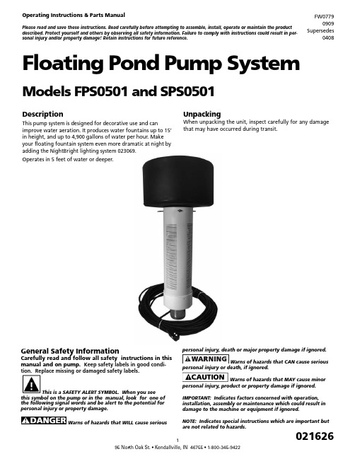
DescriptionThis pump system is designed for decorative use and canimprove water aeration. It produces water fountains up to 15’ in height, and up to 4,900 gallons of water per hour. Make your floating fountain system even more dramatic at night by adding the NightBright lighting system 023069.Operates in 5 feet of water or deeper.UnpackingWhen unpacking the unit, inspect carefully for any damage that may have occurred during transit.Floating Pond Pump SystemModels FPS0501 and SPS0501Operating Instructions & Parts ManualPlease read and save these instructions. Read carefully before attempting to assemble, install, operate or maintain the product described. Protect yourself and others by observing all safety information. Failure to comply with instructions could result in per-sonal injury and/or property damage! Retain instructions for future reference.FW07790909 Supersedes0408General Safety InformationCarefully read and follow all safety instructions in this manual and on pump. Keep safety labels in good condi-tion. Replace missing or damaged safety labels.This is a SAFETY ALERT SYMBOL. When you seethis symbol on the pump or in the manual, look for one of the following signal words and be alert to the potential for personal injury or property damage.Warns of hazards that WILL cause seriouspersonal injury or death, if ignored.Warns of hazards that MAY cause minorpersonal injury, product or property damage if ignored.IMPORTANT: Indicates factors concerned with operation, installation, assembly or maintenance which could result in damage to the machine or equipment if ignored.NOTE: Indicates special instructions which are important but are not related to hazards.Never enter the watereither wading, swimming or in a boat with thepump power on, as this may result in severecarefully. Failure to follow could result in serious bodilyinjury and/or property damage.shall be in accordance with National ElectricCode (NEC) and all applicable local codesand ordinances. A licensed electrician shouldperform installation.“NO SWIMMING” ANDOR WARNING SIGNS SHOULD BE POSTED PERSTATE AND LOCAL CODES.Please affix included warning label to powerreceptacle or junction box.100ft power cord with three prong GFI plug. –Must connect to properly grounded receptacleof grounding type. Do not remove groundpin on plug. Do not extend the cord length by splicing orTHIS UNIT, WITH THE GFI, TO A PROPERLYGROUNDED RECEPTACLE MAY RESULT INto a circuit equipped with a fuse or circuitbreaker of ample capacity.Always disconnect powersource before performing any work on ornear the motor or its connected load. If thepower disconnect point is out-of-sight, lock itin the open position and/or tag it to prevent unexpectedapplication of power. Failure to do so could result in fatalelectrical shock or bodily injury.DO NOT handle pump withwet hands or when standing in water asfatal electrical shock could occur. Disconnectmain power supply before handling systemfor any reason.from coming in contact with sharp objects,oil, grease, hot surfaces or chemicals. DONOT kink the power cable. If damagedbox, fused disconnect switch, or covers open(either partially or completely) when notbeing worked on by a competent electricianor repairman.Always use caution whenoperating electrical controls in damp areas.If possible, avoid all contact with electricalequipment during thunderstorms or extremedamp conditions.equipment in protected area to preventmechanical damage which could produce seriouselectrical shock and/or equipment failure.DO NOT use this system topump flammable liquids such as gasoline, fueloil, kerosene, etc. Failure to follow the abovewarning could result in property damage and/or personal injury.Do not pump water above 120 degreesFahrenheit.Water leaving nozzle is at high velocityand can cause bodily injury if contact is made.in swimming pool areas.!to the State of California to cause cancer and birth defects orother reproductive harm.!coming out the bottom and protected from direct rainfall.INSTALLATION INSTRUCTIONS1. Only install this system in ponds where no swimming,wading, boating or fishing is allowed while fountain isoperating. Disconnect power to pump before fishing orentering the water.2. Post appropriate warning signs per local and state codes.3. Inspect pump system for damage before installing inpond. Check that all bolts and screws are tight. Check forany bent prongs or a cracked case on the GFI.4. The unit ships with one spray nozzle attached. To changeto one of the other 2 nozzles, remove the 4 screws fromthe nozzle then replace with desired nozzle. Refer toFigures 1, 2 & 3 for spray pattern appearance. Nozzlesare marked “This side up.” Make sure the o-ring isseated in groove before installing nozzle. Tighten screwsuntil seated, approximately 10 to 12 in-lbs.5. Attach nylon anchor ropes to 3 eyebolts located at topof screen. Secure (make sure rope is tight) to weightsplaced on pond floor or stakes on pond shore. Whenusing weights to anchor the pump, place weightsapproximately 10 feet from unit. Alternately, two anchorropes placed 180 degrees apart can be used, but 3 ropeswill provide the best stability.6. Before connecting the unit to the power receptacle,check to insure there is no leakage to ground. This canbe done by using an ohm meter and setting the scale toits highest setting (i.e. Rx100K). Connect one ohmmeter lead to the unit power cord ground (round prong) and to one of the flat prongs. It should read infinite or at least 2 mega ohms. Repeat with the other prong. If reading is below 2 mega ohms on either prong contact Customer Service Help Line listed at bottom of page.7. Do Not Operate System on an Extension Cord. If no power is accessible at the pond, contract a licensed electrician to install the proper power supply in accordance with National Electric Code and all applicable local codes and ordinances.8. After installing the unit, checking ground andconnecting power to the unit, the unit can be powered up. Check operation of the GFI by pushing the “Test” button, the unit should stop. Pushing the “Reset” button should restart the unit. If pressing the “test” button does not stop the unit, immediately shut off power to unit and contact Customer Service Help Line listed at bottom of page.NOZZLE PATTERNST h is s id eu p Figure 1: Water Lily - An eye-catching combination spray. Item #2AT h i s s id eu pFigure 2: Sky Cannon - A dramatic single plume of water. Item #2BT h i s s id eu pFigure 3: Water Trumpet - A symmetrical inverted bell shape.Item #2CFigure 4: Typical InstallationINSTALLATION CHECK LIST☐ Read installation instructions and warnings ☐ Post appropriate warning signs ☐ Install desired spray nozzle ☐ Install and anchor unit in pond☐ Check insulation resistance to ground ☐ Power up unit☐ Test operation of GFI by pressing the “Test” Button.☐ File instructions for future reference REQUIRED TOOLS & SUPPLIES• #2 Phillips screwdriver • Nylon rope to anchor unit• Stakes or weights for anchoring unit• Ohm meter to check insulation resistance to groundWINTER STORAGE• Rinse unit with clean water to remove any build-up on unit.• Check unit for any damage.• Store unit in heated space in freezing climates.The pump motor is water lubricated and is factory filledwith an antifreeze solution. During operation the antifreeze may exchange, thru the filtered check valve, with the pond water. In climates where freezing may occur, the unit must be stored in a heated storage space to prevent damage to the motor.TROUBLESHOOTING GUIDE PROBLEM POSSIBLECAUSESCORRECTIVE ACTIONUnit won’t run Circuit break-er trippedReset circuit breaker GFI Tripped Reset GFINo or low spray Blockedscreen ornozzle, miss-ing or dam-aged o-ring,or incorrectlyinstallednozzleDisconnect power. Clean screenand/or nozzle. Check that o-ring isundamaged and seated in groove.Check that nozzle is installed prop-erly (nozzles are marked “This sideup”). Check depth of pond. If lessthan 5 feet deep, move to deepersection. Restart unit.GFI Trips Electricalstorm can tripGFIReset GFIShort in sys-tem Disconnect power and check cord for damage. If cord is damaged contact Customer Service Help Line listed at bottom of page for replacement.Unit spins Anchor ropeloose Check anchor rope and re-attach if necessaryItem #Qty Part No.Description16021624Screw - #10 x 3/4 Pan Head High-Low 2A1021617Nozzle - Water Lily2B1021618Nozzle - Sky Cannon2C1021619Nozzle - Water Trumpet31021622O-Ring - AS568A - 041 (3” ID x 3/18” OD) 44021628Bolt - SS 1/4-20 x 3/454021629Lockwasher - 1/4”61021707Mounting Flange71021534Float81021713Pump End91021740Motor 1/2 HP 115V104127021Locknut - SS 5/16-24111021715100 ft. power cord with GFI11A1021614GFI123021609Eye Bolt - SS 1/4-20 x 2-1/2133021623Locknut - SS 1/4--20141021608Screen151021611Screen Cap161021613Strain Relief172021625Warning DecalFlow (GPH)Spray Height(Ft.)PatternImagePatternName 490015Thissi de upIL053Thissi de upThissi de upWater Lily- 2A 330015Sky Cannon- 2B 270013WaterTrumpet - 2C15161112(A/B/C)345671710911131214811A。