圆钢管T形节点
钢管混凝土拱桥管节点应力及应力集中有限元分析
1.1.2 钢管混凝土结构的特点
钢管混凝土是指在钢管中填充混凝土而形成的构件,是使其二者有机结合的 一种组合结构,其本质上属于箍套混凝土。钢管混凝土是在劲性钢筋混凝土及螺 旋配筋混凝土的基础上演变和发展起来的,按截面形式的不同,可分为方钢管、 圆钢管和多边形钢管混凝土。在实际工程中,应用最广泛的是圆钢管混凝土,且 管内只浇灌素混凝土,不再配置钢筋 日
学位论文版权使用授权书
本学位论文作者完全了解学校有关保留、使用学位论文的规定,同意学校 保留并向国家有关部门或机构送交论文的复印件和电子版,允许论文被查阅和 借阅。本人授权湖南大学可以将本学位论文的全部或部分内容编入有关数据库 进行检索,可以采用影印、缩印或扫描等复制手段保存和汇编本学位论文。
(1)简要介绍了钢管混凝土的结构特点及钢管混凝土在拱桥中的发展情况, 提出了钢管混凝土拱桥的设计需注意的问题,并介绍了圣维南原理及其在钢管混 凝土中的应用;
(2)根据已建四管桁式钢管混凝土拱桥—湖南益阳茅草街大桥,选取工程中 三类典型节点—DTY 型、XYT 型、DTDY 型管节点为研究为对象,基于 ANSYS, 建立了钢管混凝土拱桥的节点实体模型,分析和比较了它们的静力性能,讨论了 其应力变化情况;
(3) the analysis and calculation on variation of stress concentrate factor for both concrete-filled steel tubular and hollow steel tubular DTY joints, XYT joints, DTDY joints under the axial strength or axial and bending loadings together function in brace along with the variation of diameter of braces and the included angle of braces and chords the have carried out. The results show that the concrete-filled steel nodes are more obvious than the empty steel tube nodes on stress concentrate phenomenon and as well as nodes under the function of axial strength than axial and bending loadings together function in brace.
T型方钢管相贯节点轴压性能有限元研究与试验验证
口d e c r e a s e s , t h e s t r e s s s t r e n g t h e n i n g a n d t h e d u c t i l i t y o f s p e c i m e n s i n c r e a s e . A s t h e v l a u e o f 3 / i n c r e a s e s d ,
生弦杆相贯面凹陷和侧壁鼓 凸的现象; 试件在加载全过程具有较强的变形能力; 值越小, 试件 的应
力强化越 时显 , 延性 也 越 小 ; 试 件 极 限 承 载 力 随 着 值 的 增 大 而增 大 ; 有 限 元模 拟 与 试 验 吻 合 度
较 高.
关键词 : T型方钢管相贯节点 ; 有限元分析 ; 轴压性能 中图分 类号 : T U 3 9 2 . 3 文献标 志码 : A D O I : 1 0 . 3 9 6 9 / j . i s s n . 2 0 9 5— 4 7 6 X. 2 0 1 3 . 0 3 . 0 2 2
圆形钢管规格及截面特征表

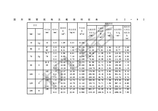
圆形钢管规格及截面特征表 表2-92 直径 外径D (mm) 壁厚t (mm) 截面面积 (cm2) 理论重量 (kg/m) 外表面积 (m2/m)
截面特征 毛截面惯性矩I (cm4) 毛截面抵抗矩W (cm3) 回转半径i (cm) 抗扭惯性矩Ik (cm4) 截面重心到边缘距离Z0 (cm)
(mm) (in)
40 1½ 48 3.5 4.89 3.84 0.151 50 2 57 3.5 5.88 4.62 0.179 21.14 7.42 1.90 42.27 2.85 60 3.5 6.21 4.88 0.188 24.88 8.30 2.00 49.77 3.00
70 2½ 75.7 3.8 8.56 6.64 0.237 55.16 14.59 2.54 110.32 3.78 76 4.0 9.05 7.10 0.239 58.81 15.48 2.55 117.62 3.80 5.0 11.15 8.75 0.239 70.62 18.59 2.52 141.25 3.80
80 3 88.5 4.0 10.62 8.34 0.278 94.99 21.44 2.99 189.97 4.43 89 4.0 10.68 8.40 0.280 96.68 21.73 3.01 193.36 4.45 5.0 13.20 9.24 0.280 116.79 26.24 2.98 233.58 4.45
100 4 108 4.0 13.07 10.30 0.339 176.95 32.77 3.68 353.91 5.40 6.0 19.23 15.09 0.339 250.90 40.46 3.61 501.81 5.40 114 4.0 13.82 10.85 0.358 209.35 36.73 3.89 418.70 5.70 125 5 133 4.0 16.21 12.73 0.418 339.53 50.76 4.56 675.05 6.65 6.0 23.94 18.79 0.418 483.72 72.74 4.50 967.43 6.65 140 4.5 19.16 15.40 0.410 440.12 62.87 4.79 880.24 7.00
圆形钢管规格及截面特征表
11.04
31063.57
16.25
注:I——毛截面惯性矩;W——毛截面抵抗矩;i——回转半径;Ik——抗扭惯性矩;Z0——截面重心到边缘距离。
2-5-3 钢管结构计算
1.适用于不直接承受动力荷载,在节点处直接焊接的钢管桁架结构。
钢管外径与壁厚之比,不应超过100( )。轴心受压方管或矩形管的最大外缘尺寸与壁厚之比,不应超40 。
2.钢管节点的构造应符合下列要求:
(1)主管外径应大于支管外径,主管壁厚不应小于支管壁厚。在支管与主管连接处不得将支管穿入主管内。
(2)主管和支管或两支管轴线之间的夹角θi不宜小于30°。
(3)支管与主管的连接节点处,应尽可能避免偏心。
(4)支管与主管的连接焊缝,应沿全周连续焊接并平滑过渡。
(5)支管端部宜用自动切管机切割,支管壁厚小于6mm时可不切坡口。
9.37
11702.46
13.65
11.0
90.62
71.09
0.858
7782.56
570.15
9.27
15565.11
13.65
300
12
325
8.0
79.67
62.54
1.021
10013.94
616.24
11.21
20027.81
16.25
13.0
124.42
100.03
1.021
15531.78
62.87
4.79
880.24
7.00
150
6
159
4.5
21.84
17.15
0.500
652.27
82.05
5.46
矩形钢管混凝土T型受压节点受力性能的有限元分析

凝 土 T 型 受 压 节 点 荷 栽 一 变形 关 系 曲线 进 行 计 算 , 算 曲 线 与 试 验 曲 线基 本 吻 合 , 对 矩 形 钢 管 混 凝 土 T 型 受 压 计 并
维普资讯
尧 国 皇 , : 形 钢 管 混 凝 土 T 矩
矩 形 钢 管 混 凝 土 T型 受压 节 点 受 力性 能 的
有 限 元 分 析
尧 国皇 宋 宝 东 黄 用 军 谭 伟
Y oGu h a g S n a d n H a g Y n jn T nWe a o u n o gB o o g u n o gu a i
( ChiaCo tu to ( h n he n nsr cin S e z n)De in I e n to a S e z n 5 8 33 sg ntr a in l h n he 1 0 )
s f war ot e,a he c lul e c r e a r e ge r ly w ih t e pe i e a ne nd t ac atd u v s g e ne a l t he x rm nt lo s, t n a l i la deor a i n he nayss of o d— f m to
采 用 有 限 元 软 件 ANS YS对 其 工 作 性 能 进 行 了计 算, 计算 结 果与 试验 结果 吻合 较好 。同时 文献 E ] s 也 提 出 了矩形 钢 管混 凝 土 受 压 节 点 的设 计 方 法 , 关 有 研究 成 果被 形钢 管混 凝土 结构 技 术规程 ) C C 矩 ) E S (
钢管相贯节点的研究现状和趋势

何参数 ( g 、 、 ) 支杆作用 位置 和空间作 用对节 点极 限承载力
的影响 ” 。20 0 7年武振宇 、 陈鹏 、 王渊 阳对轴 向往 复荷载作 用 下的 l 2个 T型方管节点进行 了试验研 究 , 结果 表 明, 节点 的破坏模式主要是受 压时 弦杆表 面塑 形变 形和受 拉时 焊缝 的边缘开裂 , 致在支 弦杆交 汇处 被拉 断 、 导 节点滞 回曲线饱
Байду номын сангаас
尺寸足尺试验数据 的 比较 , 明了该模型计算 K型节点尤其 表 是大尺寸 K型节点的承载力有较好 的准确性 , 它适用于支管
不重叠或 重 叠较 小 的 K 型节 点 a。2 0 t l 02年 陈 以一 、 沈祖
任何假想模 型 , 而是 直接根 据试验 结果 得 出的 , 国以 日本 我
规范为基础 , 综合 了 A I P 规范 、 U E R规范及 大连 理工 大学 、 同
管表面局部 屈曲。在有 限元 分析 中有些 节点 的失 效式 为几 种失效模式 的综 合。 13 各 国规 范有关管节点 的设计计 算 . 世 界各 国对相贯节 点 的承载 力做 了大量 的试 验 。美 国
焊 接 学 会 焊 接 结 构 规 范 ( WS 、 国 石 油 学 会 规 范 ( P ) A )美 A I、
r Oi l 1一I l 1
图 1 相 贯 节 点
以形 成多种空间节点形式 。
1 2 钢 管 相 贯 节 点 失 效模 式 .
l …了部分钢管节 点形式 给
本文结合管节点 的不 同研 究方法 , 绍钢管相 贯节点 的研究 介 现状和 目前 已取 得 的成 果 , 需 要深 入探 讨 的课题 提 l 了 对 叶 』
研究 。
平面内弯矩作用下T型铸钢节点承载性能分析

rtayaa s ato t er gpr racstdr ed gm m n8 Fr at -it b ai em t ei l nl iesji ai eo ne e ni o et. o sTjn, ym kn go ey cl ys nb n fm a r b n e o g r
eii atuuajis ei i eictn.Bth c ita,i m s(s¥ ts ed gm m n , xtgcstbl n s nn s c aos u t f tsht n ot ̄ e,iibni o et sn ro td g g p f i i e a l f n s
Slwr 软件建立三维模型, odo s i k 采用通用有限元软件 As 进行非线性分析。结合有限元计算结果 , T ns y 对 型铸钢节点
在平面内弯矩作用下的承载力进行了参数分析 。 给出了T型铸钢节点在支管受平面内弯矩作用下的极限承载力公
式。在焊接管节点几何参数的基础上 , 铸钢节点增加了由 C D Ewr 首次提出的倒角系数 l . .da s d D 。本文重点讨论了该
m d l s gsl w r s o .ie r n ls a o eu igA ss o o e i i ok ,N n 1 a ay i w sd n s n y ,acmmeca nt l n rga e a u n od n a s n ril i ee i f e me t ormm .P 。 p mm tee u t n f lmaela igcp ct eie o tersl f nt lme t n lssaepee tdfr er q ai so t t dn a a i d r df m eut o f i ee n ayi r rsne i o ui o y v r h s i e a o
圆钢管空间KT型相贯节点极限承载力分析.
圆钢管空间KT型相贯节点极限承载力分析【中文摘要】空间KT型相贯节点是三角形钢管桁架结构体系中一种常见的节点形式,现行《钢结构设计规范》GB50017-2003还不能解决此类节点的设计题目。
本文考虑材料非线性和几何非线性,采用ANSYS有限元程序对空间KT型圆钢管相贯节点进行了有限元分析。
本文的主要研究内容如下:①利用ANSYS软件建立空间KT型节点有限元模型,通过对不同计算模型的分析结果的对比确定合适的计算模型。
②与平面节点相比,空间效应(荷载效应、几何效应)对空间节点极限承载力的影响不可忽略。
因此,首先探讨了空间效应对KT型节点承载力和受力性能的影响,得出了T支管与K支管在节点处的承载力(考虑T支管受拉、压两种情况)相关曲线,及支管轴力比m对节点极限承载力的影响。
③研究了空间KT型节点的破坏模式,对其进行了进一步分类,并根据分类选取有代表性的支管轴力比m分别探索了各加载阶段节点变形、节点应力和塑性区分布规律等重要受力性能。
④分析KT型节点极限承载力随主管径厚比γ、支管与主管外径比β以及T支管与K支管横向夹角φ等参数变化的规律;同时,针对不同的支管轴力比m分别还研究了主管轴压应力n对节点极限承载力的影响。
分析表明,除φ外,其余参数对节点极限承载力的影响均较为明显;主管受轴压时节点极限承载力下降,其降低程度可按本文建议的φn来计算;节点破坏时支管的极限荷载是相互关联的,其相关关系可参考本文建议公式。
⑤通过与现行规范GB50017-2003中平面节点公式的比较分析,提出了圆钢管空间KT型相贯节点极限承载力设计值的建议公式。
');【Abstract】 Multiplanar CHS KT-joint is one of the typical joint configurations in space tubular truss with triangular section. However, the present code GB50017-2003 can not figure out the design of these joints. Finite element analysis of ultimate capacity of multiplanar CHS KT-joints is carried out with ANSYS program in this ***, which takes geometric and material nonlinearity into consideration.The main research content in this article is as follows.①First, the models of multiplanar CHS KT-joints are established by using ANSYS program.Through comparative analysis of different models t he appropriate model is established.②Compared with uniplanar joints, space effect, which include the load effect and geometric effect, is an extra and important factor influenced the ultimate capacity of multiplanar joints and can’t be ignored. So the influence of the space effect on the ultimate capacity of KT-joints is studied by FEM. And the intersection curves of the ultimate capacity of T branch and K branch are obtained. Also the influence of the axial force ratio of T branch to K branch on the ultimate capacity of KT-joints is studied.③Finally the failure modes of multiplanar CHS KT-joints are discussed, and the detailed classification is given. Also the history of node displacement, node stress and plasticity spread with loading of different m isdes cribed.④The effect laws of the parametersγ,βandφto theultimate capacity are depicted. Meanwhile the influence of compressed stress ratio in chord n on the ultimate capacity of different m is studied. It shows the influence of all parameters exceptφon the ultimate capacity is obvious. While the chord is compressed, the ultimate capacity decreases, this *** suggestφn could be used to calculate the decreased degree. While KT-joint destroy, the ultimate capacities of branches are interdependence, their relationship could refer to the formula proposed in this ***.⑤Compared with the results got from the formulas of uniplanar joints in code GB50017-2003, the formula of multiplanar CHS KT-joints which can be used in design is propose.。