[PPT]非饱和土力学大师Fredlund的演讲英文
非饱和土力学讲义(Fredlund在香港科大)chapter2ustmod
Soil Mechanics for Unsaturated Soils Professor Delwyn G. Fredlund•The study of a multi-phase system such as an unsaturated soil, requires an understanding of the properties of each component phase.rties of each phase of an unsaturated soil; ii.) an understanding of the interaction between air and water; iii.) establishment of useful volume-mass relations for solving engineering problems.Additional notes:Soil particles &contractile skinbehave as solidsAir & waterbehave as fluids•An unsaturated soil is commonly referred to as a 3-phase system composed of: i.) solids (soil particles); ii.) water; iii.) iii.) air.•The air-water interface (i.e., the contractile skin) warrants inclusion as an additional phase due to its unique and specific properties.•The contractile skin interacts with the soil particles in an independent manner and can significantly change the mechanical behavior of an unsaturated soil.fore can be neglected in volume-mass relationships.•The air phase might be present in an unsaturated soil either in a continuous or an occluded (bubbles) form.Additional notes:Required tounderstandthe stress stateanalysisSufficient forMapping phasechanges•Gravimetric and volumetric relationships for unsaturated soil are based on various mass and volume ratios of the component phases.•A rigorous microscopic analysis of the volume-mass properties of an unsaturated soil mass requires the inclusion of the contractile skin.•Using a macroscopic (phenomenological) approach, an unsaturated soil can be considered as a three-phase continuum system.•The most important property of the contractile skin is its ability to exert a tensile pull which is a consequence of the surface tension generated between the two pore-fluid phases (i.e., air and water).Additional notes:•Air is a mixture of several gases and varying amounts of water vapor. water vapor is present.•Air is compressible and its density requires additional considerations in terms of pressure and temperature.Additional notes:Air is a mixture of several gases that act in an independent manner•Air is considered to behave as an “ideal gas” under pressures and temperatures commonly encountered in geotechnical engineering. •The molecular mass of air , ωa , depends on the mixture of dry air and water vapor.lar mass ofwater vapor is 18.016 kg/kmol.from0.000002% to 5% (Harrison, 1965). Additional notes :Density is equal to mass per unit volume Density of air is directlyproportional to the absolute air pressure•Amounts of Nitrogen (N 2) and Oxygen (O 2) are essentially constant.•Carbon dioxide (CO 2) content in air may vary depending on the rate of consumption of fossil fuels. Additional notes:•Water is essentially a homogeneous substance the world over, except for variations due to salts and isotopes of hydrogen and oxygen (Dorsey, 1940).•Distilled water under the pressure of its saturated vapor is called pure, saturated water.•The density of water must be measured experimentally.•Variations in the density of water due to temperature differences are more significant than variations due to applied pressure.Additional notes:SURFACE TENSION •A molecule in the interior of the water experiences equal forces in all directions whilea water molecule in the contractile skin experiences an unbalanced force towards the interior of the water.actile skin.alled its surface tension,T s (i.e., units of N/m 2).•Contractile skin behaves like an elastic membrane.-water surface can be related to surface tensionand the radius of curvature by considering equilibrium.Additional notes:Surface Tension Phenomena•Surface tension is measured as the tensile force per unit length along the contractile skin (i.e., units of N/m).•Surface tension is tangential to the contractile skin surface. Its magnitude decreases as temperatures decreases.u a , that is greater than thewater pressure, u w .•The pressure difference, (u a -u w ) is referred to as matric suction.Additional notes:•Contractile skin forms a warped or saddle-shaped surface (i.e., 3-D membrane) that has different curvatures along two orthogonal (i.e., R 1and R 2for example).o C.-water interface.Additional notes:State Diagram for Water(from van Haveren and Brown, 1972) •Water phase can exist in one of three states: i.) solid state as ice; ii.) liquid state aswater; iii.) gaseous state as water vapor.•The vaporization curve is also called the vapor pressure curve of water.•The fusion curve separates the solid and liquid states.•The sublimation curve separates the solid and vapor states.•Triple point of water is achieved at a temperature of 0o C and a pressure of 0.61 kPa.Additional notes:•The vaporization curve represents an equilibrium condition between the liquid and vapor states of water.•At equilibrium, evaporation and condensation processes occur simultaneously at the same rate.•Rate of condensation depends on the water vapor pressure it reaches at itssaturation value on the vaporization value.•Evaporation rate depends only on temperature.•Water vapor is mixed with air in the atmosphere, and has no effect on thebehavior of the water vapor.•Water vapor may not be in equilibrium with adjacent water. Water vapor in air can be under-saturated, saturated or super-saturated depending on the partialpressure of water vapor.•The degree of saturation with respect to water vapor is referred to as relative humidity, RH.Additional notes:•Water molecules form a lattice structure with openings referred to as a “cage” that can be occupied by gas.•Air dissolves water and fills the “cages” which comprise approximately 2% by total volume.Additional notes:•The volumetric coefficient of solubility, h,varies slightly with temperature.•The rate at which mass is transferred across a unit area is equal to the product of the coefficient of diffusion, D,and the concentration gradient.•In the diffusion of air through water, the concentration difference is equal to the difference in density between the free air and the dissolved air in the water.•The pressure difference between the free air and the air dissolved in the water becomes the driving potential for the free air to diffuse into the water.•The coefficient of diffusion for air through the pore-water in a soil appears to differ by several orders of magnitude from that for air through free water.Additional notes:•Volume of air dissolved in water is essentially independent of air or water pressures.•Absolute pressure of the dissolved air is equal to the absolute pressure of the free air under equilibrium conditions.•Volume of air dissolved in water is constant for different pressures.•Ratio between the mass of each gas that can be dissolved in a liquid and the mass of the liquid is called the Coefficient of Solubility , H.•Coefficients of Solubility are referenced to a standard pressure of 101.3 kPa.•Ratio of the volume of dissolved gas, V d ,in a liquid to the volume of the liquid is the Volumetric Coefficient of Solubility , h.Additional notes :•A cylinder with a piston and porous stone analogy is useful in visualizing and analyzing the behavior of air-water mixtures.•The “porous stone” has pores equaling 2% of its volume. The “porto simulate the behavior of water.•An initial pressure is applied equally to the free air and the “•An imaginary valve is placed at the boundary between the free air and the “porous stone”.•When the piston is loaded, it compresses the free air above theporous stone inaccordance with Henry’s law.•Henry’s law states that the mass of gas dissolved in a fixed quantity of liquid, at constant temperature, is directly proportional to the absolute pressure of the gas above the solution (Sisler et al., 1953).•After several increases of the applied loading, all free air will have moved into the “porous stone”, and any additional applied load will be carriedAdditional notes:•The water lattice is relatively rigid and stable (Dorsey, 1940) and the density of water changes little as a consequence of the presence of the dissolved air.•Dissolved air has no measurable effect to the density of water at a temperature of about 22o C.Additional notes:•An unsaturated soil has air and water pressures at different magnitudes.•The mass of air going into or coming out of the water is time dependent.•The amount of gas dissolved in water is referred to as its Solubility .•The rate of solution of a gas is referred to as its Diffusivity .Additional notes:•The volume-mass relations of the soil particles, water, and air phases are useful properties in engineering practice, particularly for an unsaturated soil.•Both mechanical and hydraulic behaviors of an unsaturated soil mass are highly dependent on the relative proportion of the three component phases (i.e., solid, water and air).•Soil properties such as degree of saturation, porosity and void ratio express volumetric proportions involving the three phases of an unsaturated soil mass.•The above volumetric properties associated with the density of each phase allows the definition of all the index properties commonly utilized in engineering practice to characterize the state of a soil mass.Additional notes:•Each phase of an unsaturated can be expresses as a percentage of the totalvolume by using the definition of porosity.•The volume of the contractile skin can be assumed to be negligible.•The porosity with respect to the water phase, n w ,is equivalent to the volumetric water content, θw .•A soil mass might change its total volume in response to changes in the stress state applied. However, the volume of solid particles is constant.•Void ratio of a soil mass expresses the ratio of the void volume to the volume of the solid particles.Additional notes:•The degree of saturation expresses the percentage of void space filled by the liquid phase (i.e., water).dry (i.e., S = 0%),saturated (i.e., S = 100%) or unsaturated ( 0% < S < 100%).•The transition zone between a continuous air phase and occluded air bubbles occurs when the degree of saturation is between approximately 80-90%.•The water content can also be measured either in a gravimetric manner (i.e., ratio of water to solids mass) or in a volumetric manner (i.e., ratio of water volume to total volume).Additional notes:•Two commonly used soil density definitions are the total density and the dry density. Total density is called the bulk density.•Dry density of a soil mass is dependent upon the mineralogy of the solidphase, in terms of specific gravity,G s , and the porosity of the soil structure.•The saturated density of the soil is the total density of the soil for the casewhere the voids are filled with water (i.e., S = 100%).•The buoyant density of a soil is the difference between the saturated density of the soil and the density of water.•A “basic volume-mass relationship” for a soil mass can be derived by using the idealized diagram where each soil phase is defined by its volume and its mass.Additional notes:•Volume-mass relationships in engineering practice neglect the mass of airphase, but consider the volume of the air phase.•The expression (Se = wG s )is the basic volume-mass relationshipcommonly used in engineering practice and it represents the continuityequation for a soil mass.•Additional notes:•Density, ρis the ratio of mass to volume. Each soil phase has its own density.•Specific gravity of the soil particles, Gs ,is defined as the dimensionless ratio between thedensity of the soil particles and the density of water at a temperature of 4o C underatmospheric pressure conditions (i..e, 101.3 kPa).•Density of water at 4o C and at 101.3 kPa is 1000 kg/m 3.•Specific volume, v o ,is the inverse of density (i.e., ratio of volume to mass).•Unit weight, γis the product of density, ρ, and gravitational acceleration, g,(i.e., 9.81 m/s 2).Additional notes:•In engineering practice, the total density is often increased by imposing a reduction in the void volume of a soil mass.•Volume of pore-water in a soil mass is highly dependent uponenvironmental conditions and therefore is often a variable to be considered.•The dry density is independent of the volume of the pore-water and is often used in semi-empirical relationships for the soil.Additional notes:•The dry density curve corresponding to a degree of saturation of 100 % is called the “zero air voids”, ZAV, curve.•The dry density curves curves for different degrees of saturation should be presented in connection with soil compaction data.•Compaction is a mechanical process used to increase the dry density of soils (i.e., densification).Additional notes:-Start of process:•The basic volume-mass relationship (i.e., Se = w Gs ) applies to anycombination of S, e and w , and therefore it can be used to obtain changes in any of these properties when the other two properties are defined.•The basic volume-mass relationship can therefore be used to deriveequations associating changes of S, e and w .Additional notes:•Soil mixtures can occur in various forms in nature.•Mixture of soil particles and air constitutes a dry soil while a mixture of soil particles and water constitutes a saturated soil.•Unsaturated soils lie between dry and saturated soil conditions and constitute a mixture of soil particles, air and water in differing percentages.•The density of a soil mixture can also be formulated for situations where there is a change in the volume of air due to compression under undrained conditions. •The analogy of the piston-porous stone is a useful tool to derive the formulation of the density of the soil by considering the air compression.•In the above formulation, Boyle’s law is applied to the free and dissolved air under isothermal conditions.Additional notes:•Under isothermal conditions, the ratio of the density to the absolute pressure of the air phase (i.e., free and dissolved air) in a soil mixture is constant.•The final density of water is computed as the ratio of the total mass of water and dissolved air to the total volume of water and dissolved air under final equilibrium conditions.Additional notes:•The conservation of mass is herein applied to a system (i.e., soil mixture) under isothermal conditions, therefore, all the previous equations can be applied. •The total density of the soil mixture is therefore a function of the constant densities and volumes of water and solid phases as well as of the variable density and volume of the air phase.•The total density formulation can be applied to the definition of particular cases where one of the three phases (i.e., solid, water and air) in a soil mixture is not present.Additional notes:•The first equation above is a general mixture equation for density after the soil has been subjected to a change in air pressure.•The volume of dissolved air , V d ,is related to the volume of water, Vw ,by thevolumetric coefficient of solubility, h (i.e., V d = hV w ).•The equation incorporates the effect of air going into solution due to the change in the air pressure.•Where air does not have time to dissolve in water, the volumetric coefficient of solubility, h,might be set to zero.•The air-water mixture always has a density between that of air and water.•The density of an air-water mixture can be obtained from the general equation is obtained by setting the volume of the soil particles, Vs ,to zero, and the initial voidratio, e i ,becomes infinity.Additional notes:。
不饱和土力学英文课程 课件CHAP 6_Mech of Unsat Soils_Vanapalli_2016
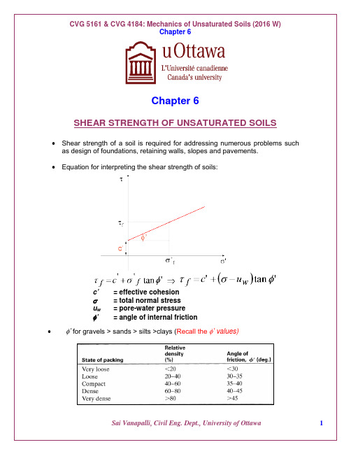
Chapter 6SHEAR STRENGTH OF UNSATURATED SOILS •Shear strength of a soil is required for addressing numerous problems such as design of foundations, retaining walls, slopes and pavements.•Equation for interpreting the shear strength of soils:c’ = effective cohesionσ = total normal stressu w= pore-water pressureφ’ = angle of internal friction•φ’ for gravels > sands > silts >clays (Recall the φ’ values)•Saturated shear strength of soils is related to one stress state variable;namely, effective stress, (σ – u w).•Shear strength parameters are commonly determined using triaxial shear tests, direct shear tests, or ring shear tests.Figure. Triaxial shear test equipment: a versatile equipment in whichdifferent types of drainage conditions can be introduced and tested •The shear strength of a saturated soil is commonly described extending the Mohr-Coulomb failure criterion from triaxial shear tests and the effective stress concept as given below:Figure. Mohr-Coulomb shear strength failure envelope for a saturated soil using triaxial shear test results (modified after Terzaghi, 1943N σ′=As=Figure: Shear strength envelope from direct shear strength test results Triaxial shear test (Versatile test)Figure: Comparison of CU and CD shear strength test results of a cohesive soil using identical soil samples.Figure: Reasons associated with the changes in shear strength from CU and CD tests.Figure: Comparison of CD and UU shear strength test results of a cohesive soil using identical soil samplesFigure: Comparison of CD and UU shear strength test results of a cohesive soil using identical soil samplesFigure: Comparison of shear strength envelops for UU, CU and CD tests•Unconfined compression test: Special case of triaxial shear test with no confining pressure (i.e., σ3 = 0).•It is convenient to measure the undrained shear strength of cohesive soils using unconfined compression tests (this value is typically used in the design of foundations).Figure: Unconfined compression test•Practical engineering applications of drained and undrained loading conditions.Drained Loading(i) Long term stability (ii) Steady state seepage (iii) Shallow foundations (iv) Slow rates of construction (v) Seepage control during constructionUndrained Loading(i) During construction (Rapid): Embankments, Cuttings(ii) Sudden draw down: Dam reservoirs, Floods(iii) No seepage control: Embankments, Cuttings(iv) Earthquake loading•Soils that are in a state of unsaturated condition have to be interpreted in terms of two stress state variables; namely, net normal stress, (σ– u a)and matric suction, (u a – u w).•The conventional triaxial and direct shear testing equipment used for testing saturated soils must be modified to test unsaturated soils.•Similar to saturated soils, shear strength testing of unsaturated soils involves two stages (i.e., first stage is loading and the second stage is shearing).•The pore-air pressure, u a and the pore-water pressure, u w, are independently maintained both during the process of loading and shearing using axis-translation technique.•The axis-translation technique is used to translate the negative pore-water pressure, u w to a pressure that can be measured without cavitation of the water.• A high air-entry disk with an air-entry value greater than the matric suction, (u a – u w) in the soil is used in order to prevent the passage of pore-air into the measuring system.•It is very important to use “identical” specimens for determining the shear strength of soil.•In the case of compacted soils, the soil specimens need to be compacted at the same initial water and dry density conditions in order to qualify as “identical” specimens.Figure: Differences in soil specimens due to the influence of soil structure associated with changes in water content.•Specimens compacted at the same water content but at different dry densities, or vice versa, cannot be considered as “identical” soils, even though their classification properties are the same.• Soils with differing density and water content conditions can yield different shear strength parameters and should be considered as different soils.• The shear strength is performed by loading a soil specimen with increasing applied loads such that a failure load is determined from the stress versus strain relationships.Figure: Strain concept used in the triaxial test• Various types of failure criteria are defined in the literature from stress versus strain relationships.Figure: Stress versus strain curves for consolidated drained tests and undrained triaxial tests• In certain cases failure load is not well defined (as shown below). An arbitrary strain rate (e.g., 12%) is selected to represent failure conditions.Figure: Strain limit as a failure condition• A series of tests should be conducted such that the shear strength is determined over a range of suction values using “identical” specimens with the same net normal stress, (σ – u a ).Figure: Shear strength envelope for an unsaturated soilFredlund et al. (1978) shear strength equation for unsaturated soils.()()b f w a fa f ff tan u u 'tan u 'c φφστ−+−+=where: τff = shear stress on the failure plane at failure,c’ = intercept of the “extended” Mohr-Coulomb failure envelope on the shear stress axis where the net normal stress and the matric suction at failure are equal to zero; it is also referred to as “effective cohesion”,(σf – u a )f= net normal stress state on the failure plane at failure,Special Design Considerations•Conventional equipment used for the measurement of the shear strength of saturated soils requires modifications when testing the shear strength of unsaturated soils.•Modifications should accommodate independent measurement (or control) of the pore-air pressure, u a, and the pore-water pressure, u w.•The axis translation technique forms the basis for these modifications such that laboratory testing of unsaturated soils with high matric suctions can be undertaken.Figure: Illustrates the application of axis-translation technique to a soil specimen with matric suction of 100 kPa.-The pore-water pressure, u w, is measured below a saturated air-entry disk that has an air-entry value of 2 bars (202.6 kPa).-Air-pressure, u a, of 180 kPa is applied directly to the specimen in order to raise the pore-air (and pore-water) pressures.-The pore-air pressure raised to 180 kPa increases the pore-water pressure by an equal amount.-Thus, the pore-water, u w,will be at a positive value of 80 kPa and will be at a positive value of 80 kPa.•Pore-air diffuses through water if the axis-translation technique is extended for a long time.•D iffused A ir V olume I ndicator (DAVI) can be used in conjunction with the measuring system in order to flush diffused air from below the high air-entry disk.•Procedure for saturating the high-air entry disk- A head of water is to be created on the disk in the triaxial or direct shear testing equipment and allow water to flow for a period of one hour using air-pressure 5or 6 times the value of the air-entry value of the stone.- The air-bubbles collected during the process from below the disk are flushed out.• A highly flexible pressure measuring system has slow response to pore-water pressures. Recommended to use a rigid measuring system.•The specimens that are used for testing the shear strength of unsaturated soils are either undisturbed or compacted.•These specimens are saturated prior to conducting the shear strength test. (i.e., typically drying path is followed).•Saturation in triaxial shear equipment is achieved by incrementally increasing the pore-water pressure, u w. At the same time, the confining pressure, σ3, is increased in order to maintain a constant effective stress, (σ3 – u w).•As a result, the pore-air pressure increase and the pore-air volume decreases by compression and dissolution into the pore-water.Triaxial Shear Tests for Unsaturated Soils•Various types of triaxial test methods are defined on the basis of drainage conditions during the application of confining pressure and during the application of shear stress.•The test methods are similar to saturated soil testing (i.e., CD, CU, UU etc..)•In most of these tests, the net total confining pressure, (σ3 – u a), generally remains constant during shear.•The axial stress is continuously increased until a failure condition is reached.•The shear strength is interpreted in terms of two stress state variables, (σ – u a) and (u a – u w).•Effective stress analysis approach can be used if the stresses at failure conditions are known.•The shear strength has to be interpreted in terms of total stresses at failure, if the pore pressures are not measured or controlled.•The total stress approach should be applied for undrained loading conditions. •Example of undrained loading conditions for unsaturated soils: Rapid loading of a fine-grained soil.Pore-air Pressure Control System•Figure above shows arrangement for pore-air pressure control using triaxial equipment.• A 3.2 mm thick, coarse corundum disk is placed between the soil specimen and the loading cap.•The disk is connected to the pore-air pressure control through a hole drilled in the loading cap, connected to a small-bore polyethylene tube.•The measurement of pore-air pressure can be achieved using a small pressure transducer.•Pore-air pressure is difficult to measure because of the ability of air to diffuse through rubber membranes, water, polythene tubing, and other materials.Table 1: Various triaxial testing conditions with necessary measurementsFigure: Various stress conditions during a consolidated drained triaxial shear test.Figure. Triaxial base plate for unsaturated soil testing. (a) Plan view of the base plate with its outlet ports; (b) cross-section of a base plate with a high air entry disk (from Fredlund and Rahardjo, 1993).Valve A: To control the pore-water pressure and to measure the water change during a drained shear test.Valve B: Used for pore-water measurement, flushing system, and diffused air volume measurement.Valve C: Pore-air pressure control or measurement.Valve D: Cell pressure control and measurement.The grooves inside the water compartment serve as water channels for flushing airbubbles that might be trapped or have accumulated as a result of air diffusion.Figure: Layout of the plumbing for modified triaxial shear testing.•Unsaturated soil testing requires several procedural checks.•The high air-entry disk should be saturated.•Attempts should be made to thoroughly flush water through the compartment in the base plate and all connecting lines, to ensure the expulsion of air bubbles.•The volume change measuring devices, including the diffused air volume indicator, should be initialized.•Briefly discuss the step-by-step procedure of conducting a CD triaxial test fordetermining the shear strength parameters for an unsaturated soil?Various Triaxial Tests for Unsaturated SoilsUndrained Tests•The procedure for performing an undrained test on an unsaturated soil specimen using the triaxial test is similar to the procedure used for performing an undrained test on a saturated soil specimen.•The unsaturated soil specimen is tested at its initial water content or matric suction. •The initial matric in the specimen is not relaxed or changed prior to commencing the test.•Both confined and unconfined compression triaxial tests can be conducted and the shear strength contribution due to suction can be interpreted in terms of total stresses.Unconfined Compression Test•The unconfined compression is a special case of undrained test and usually performed in a simple loading frame without the application of any confining pressure (i.e., σ3 = 0).Figure: Unconfined compression test apparatus•The compressive load is applied quickly in order maintain undrained conditions (the specimen is sheared in 10-15 minutes).•Theoretically, this would mean that there would be significant changes in both the pore-air pressure and the pore-water pressure in the soil specimen (i.e., a valid assumption for compacted fine-grained soils).•The pore-air and pore-water pressures are not commonly measured during compression.•The deviator stress, (σ1– σ3)is equal to the major principal stress, σ1, since the confining pressure, σ3 is equal to zero.•The deviator stress at failure is referred to as the unconfined compressive strength, q u.•Unconfined compression test is a special case of triaxial shear tests with σ3 = 0.Confined Compression Test•The undrained shear strength for the unsaturated soil increases as the confining pressure increases.Figure: Results of confined compression tests on four “identical” soil specimens (i.e., having equal density, water content and matric suction).•Note that the four “identical” soil specimens are brought to different initial states of stress, due to the changes in pore pressures under undrained loading conditions.Figure. 1. Development of pore-pressures due to undrained loading conditions •The changes in the pore-air pressures and pore-water pressures can be determined using the theory of undrained pore pressure parameters (i.e., B a and B w parameters) or can be measured at the end of the test (Fredlund and Rahardjo, 1993).•The shear increases with an increasing confining pressure. At the same time, matricsuction in the soil specimen decreases with an increase in degree of saturation accompanied by a reduction in the volume.•The diameter of the Mohr’s circles increase with an increase in confining pressure. •The envelope defines a curved relationship between the shear strength and totalnormal stress for unsaturated sols tested under undrained conditions.•Once the soil becomes saturated under the application of confining pressure a horizontal envelope develops with respect to the shear strength axis.•Once the soil is saturated the shear strength behavior is in accordance with the φu =0 concept.In a triaxial test the total stress increment d σ2 equals d σ3. The major principal stress increment of total stress, d σ1, is applied axially. The development of pore pressures in the undrained triaxial test are influenced both by the total stress increment, d σ3 and from the change in the deviator stress, d(σ1 - σ3).The changes in pore pressures are given by:()du B d D d a a a =+−σσσ313[5] ()du B d D d w w w =+−σσσ313[6]Equations 5 and 6 can be expressed in a different form as:{})31(d a A 3d a B a du σσσ−+=[7]{})31(d w A 3d w B w du σσσ−+=[8]where:a D a A a B = [9] w D w A w B =[10]Shear strength can be related to the total stresses when the pore pressures at failure are unknown. In undrained triaxial tests, the specimens when subjected to increasing loading, undergo changes in pore-air and pore-water pressures which results in changes of matric suction of the soil. Such a situation in laboratory testing is demonstrated using Figure 2. Four "identical" soil specimens subjected to different confining pressures during an undrained test are shown. The pore pressures in these soil specimens increase with the increase in confining pressure. The shear strength also increases with the increasing confining pressure. The matric suction in the soil decreases with the increase in degree of saturation accompanied by a reduction in the volume. The four identical soil specimens are brought to different initial states of stress, due to the changes in pore pressures under undrained loading conditions.Direct Shear Test for Unsaturated SoilsFigure. Modified direct shear equipment for testing an unsaturated soil specimen. (a) Plan view of the pressure chamber for a direct shear box; (b) cross-sectional view A-A of a direct shear box and pressure chamber (from Gan and Fredlund 1988).Figure: Cross-sectional view of the modified direct shear equipment •Direct shear tests are commonly conducted in consolidated drained conditions. •Test procedure:- A saturated soil specimen is placed in the direct shear box and consolidated under a vertical stress, σ.-During the process of consolidation, pore-air and pore-water pressure must be controlled at selected pressures.- A known value of matric suction is imposed on the specimen using axis-translation technique.-At the end of consolidation, the soil specimen has a net vertical stress of (σ – u a) and a matric suction of (u a – u w).-During shear, the pore-air and pore-water pressure are controlled at constant.-Shearing is achieved by horizontally displacing the top half of the direct shear box relative to the bottom half.-Shear stress is increased until the specimen fails.Figure. Stress conditions during a consolidated drained direct shear test. Matric suction, (kPa)(u - u )a w S h e a r s t r e s s , (k P a )10020030040050055050150250350450050100150200250300U p p e r e n v e l o p e B e s t f i t L o w e r e n v e l o p e c = 10 kPa= 25.5( - u )ff af tan = 34.4 kPa average = 72.2 kPa( - u )ff af Initialvoid ratio, e 0(kPa)0.7771.30.5371.60.6972.80.5172.60.5472.7( - u )ff afFigure. Variation of shear strength with respect to suction from consolidated drained direct shear test.The failure envelope can be obtained for the results of direct shear tests without constructing Mohr’s circles (see figure above). The direct shear test is useful for testing unsaturated soils due to the short drainage path in the specimen. Considerably short period of time is required for conducting direct shear test in comparison to triaxial shear test.Shear strength of unsaturated soils and its applications ingeotechnical engineering practiceS.K. VanapalliCivil Engineering Department, University of Ottawa, Ontario, CanadaABSTRACT: Several investigators over the last 50 years have contributed to ourpresent understanding of the shear strength of unsaturated soils (SSUS). Manyadvances have been made during this period with respect to the measurement,interpretation and prediction/estimation of the SSUS. The focus during the last fifteenyears has been directed more towards the development of simple techniques forpredicting or estimating the SSUS because experimental procedures are timeconsuming, need elaborate equipment, and require highly trained personnel. Shearstrength is a key engineering property required in the design of several geotechnicalstructures such as the shallow and deep foundations, earth structures includingexcavations and the stability of slopes. However, limited studies are reported in theliterature with respect to the applications of the SSUS in practice. This paper providesa brief background of the SSUS and details of how our present understanding can beextended for several geotechnical applications.•Read the above Keynote paper published by Sai Vanapalli in Asia-Pacific International Conference, Australia, 2009.•PowerPoint presentation and Paper available on the class website.。
非饱和土力学03-吸力与SWCCPPT
Suction
孔隙水与土颗粒间 相互作用而产生的 吸力中的各个部分
毛细作用 吸附作用
因溶质溶解作用 而产生的吸力
渗透作用
17
1. 吸力的概念
基质吸力的探讨 Matric suction
➢ 源自毛细与短程吸附综合作用的吸力通常定义为基质吸力, 它具有与压力一样的单位。
➢ 基质,是指细小的土颗粒。基质吸力可以看作是土基质对 水的吸持潜能。
力学角度对土的吸力及其组成下来定义。这些定义已在岩 土工程学中被广泛接受。
➢ 土中吸力反映土中水的自由能状态
4
1. 吸力的概念
自由能
➢ 什么是自由能? free energy
在热力学当中,自由能指的是在某一个热力学过程中,
系统减少的内能中可以转化为对外做功的部分,它衡量的 是:在一个特定的热力学过程中,系统可对外输出的“有 用能量”。
9
1. 吸力的概念
孔隙水总势能
p T g o c ad
➢ 忽略温度、重力与惯性的影响,促使土体孔隙水势能降低 的主要因素有: 渗透作用——孔隙水中溶质溶解的结果 毛细作用——水-气交界面曲率以及负孔隙水压力 吸附作用——固-液(即土中孔隙水)交界面附近的电场 与范德华力场作用而产生
1. 吸力的概念
基质吸力的探讨
➢ 基质吸力中的毛细部分和粘吸部分在概念上的区分是明显的,但难以 通过试验手段加以区分
➢ 基质吸力中的各个部分对非饱和土行为影响的机理并不相同。对于低 塑性的或较高含水量下的土体,基质吸力中毛细部分占支配地位;然 而对于高塑性的粘土或较低含水量下的土体,基质吸力中粘吸部分占 支配地位。
c (ua uw )
➢ 通常,基质吸力中的毛细部分可表示为:
fredlund非饱和土基质吸力的测定方法

了解不饱和土壤的行为就像潜入我们脚下的新世界揭开它的秘密的关键一步是用弗雷德伦德的方法找出母体的吸积这种方法类似于用宝图寻找土壤的含水量与其吸积潜力之间的隐藏关系。
母吸吸基本上是土壤的表达方式 "嘿,我可以吸水出自己!" 了解这一点对了解土壤在不同条件下的存留方式至关重要。
把母性吸吸视为不饱和土壤的超能力,准备被释放出来并揭示其机械秘密!
为了测量土壤的干燥程度,我们使用一种叫做抗辐射计的奇特工具。
这就像一个探测器我们坚持在地面我们感兴趣的水平。
探测器有一个小杯子触碰土壤中的水。
当土壤真的干燥时,它把水吸进杯子中,我们可以测量压力以判断土壤的干燥程度。
这有点像用高科技稻草看土壤有多渴!
必须强调,Fredlund在不饱和土壤中测量母体吸附的方法要求仔细注意测距仪的选择和安装,以及准确校准和明智地解释数据。
遵守土壤样品制备和测试程序的标准规程对于保持母体吸附测量的精确性和可靠性至关重要。
只有通过严格运用既定准则和程序,才能确保数据的完整性,并维持调查结果的有效性。
非饱和土抗剪强度公式分类及总结

非饱和土抗剪强度公式分类及总结张常光;赵均海;朱倩【摘要】The shear strength formulae for unsaturated soils were divided into five categories, such as using soil-water characteristic curve, mathematical fitting, piecewise functions, total stress indicators and other forms. Characteristics and deficiencies of the current research on shear strength formulae for unsaturated soils were analyzed. The results show that some differences in mechanical significance exist between shear strength formulae based on the effective stress and shear strength formulae based on the two-stress state variables. Different expressions of suction strength lead to diversities of the shear strength formulae. True triaxial tests of unsaturated soils are urgent need to be carried out and strength theory of unsaturated soils satisfying the actual engineering stress conditions is to be established in order to improve the theoretical basis of unsaturated soils and accelerate the process of engineering applications.%将众多非饱和土抗剪强度公式分为结合土-水特征曲线、数学拟合、分段函数、总应力指标及其他形式5类,分析了当前非饱和土抗剪强度公式的特点及研究不足.结果表明:有效应力抗剪强度公式和双应力状态变量抗剪强度公式的力学本质不同,吸附强度表达式的不同导致了抗剪强度公式的多样性,急需加强非饱和土真三轴试验研究,建立符合工程实际受力状况的非饱和土强度理论,完善非饱和土的理论基础,并加快非饱和土强度理论的工程实践与应用进程.【期刊名称】《建筑科学与工程学报》【年(卷),期】2012(029)002【总页数】9页(P74-82)【关键词】非饱和土;基质吸力;抗剪强度公式;真三轴试验【作者】张常光;赵均海;朱倩【作者单位】长安大学建筑工程学院,陕西西安 710061;长安大学建筑工程学院,陕西西安 710061;长安大学建筑工程学院,陕西西安 710061【正文语种】中文【中图分类】TU4320 引言非饱和土分布十分广泛,与工程实践密切联系的地表土几乎全都是非饱和土[1]。
高等土力学思考题与概念题
思考题第一章:1. 对于砂土,在以下三轴排水试验中,哪些试验在量测试样体变时应考虑膜嵌入 (membrane penetration)的影响?HC, CTC, CTE, RTC, RTE, 以及平均主应力为常数的TC TE 试验。
2.对于砂土,在常规三轴固结不排水(CU)压缩试验中,围压σ3为常数,其膜嵌入 (membrane penetration)效应对于试验量侧的孔隙水压力有没有影响,为什么?对于常规三轴固结排水试验对于试验有无影响?3.对于砂土,在常规三轴固结不排水(CU)压缩试验中,围压σ3为常数,其膜嵌入 (membrane penetration)效应对于试验的不排水强度有没有影响,4.在周期荷载作用下饱和砂土的动强度τd (或σd )如何表示?定性绘出在同样围压σ3,不同初始固结比σ1/σ3下的动强度曲线。
5.在一定围压下,对小于、等于和大于临界孔隙比e cr 密度条件下的砂土试样进行固结不排水三轴试验时,破坏时的膜嵌入对于量侧的孔隙水压力有何影响?对其固结不排水强度有什么影响(无影响、偏大还是偏小)?6.在土工离心模型试验中进行固结试验,如果模型比尺为100,达到同样固结度,模型与原型相比,固结时间为多少?7.举出三种土工原位测试的方法,说明其工作原理、得到的指标和用途。
8.对于粗颗粒土料,在室内三轴试验中常用哪些方法模拟?各有什么优缺点?9.真三轴试验仪器有什么问题影响试验结果?用改制的真三轴试验仪进行试验,其应力范围有何限制?10. 在饱和土三轴试验中,孔压系数A 和B 反映土的什么性质?如何提高孔压系数B ?11. 在p, q 坐标、⎺σ,⎺τ坐标和在π平面坐标下画出下面几种三轴试验的应力路径(标出应力路径的斜率)。
(1) CTC (常规三轴压缩试验)(2) p =常数,b=0.5=常数,真三轴试验;(3) RTE (减压的三轴伸长试验)。
其中:22)()()(213/)(31312132********σστσσσσσσσσσσσσ-=+=-+-+-=++=q p)(32tan 31312σσσσσθ---=第二章1.土的刚塑性本构模型与增量弹塑性模型表现的应力应变关系曲线有何区别?2.在剑桥模型中,物态边界面上的不排水三轴试验的有效应力路径向p '--q 平面的投影是不是其屈服轨迹?为什么?3.剑桥模型是否可以反映土由于剪应力引起的体积膨胀(剪胀),清华弹塑性模型是否可以反映土由于剪应力引起的体积膨胀?二者的区别是由于什么不同?4.剑桥模型的帽子屈服面能不能反映土由于剪应力引起的体积变化?它是剪胀还是减缩?5.Duncan-Chang 模型与剑桥模型都是在常规三轴试验基础上建立的,前者通过常规三轴试验确定的(σ1-σ3)~ε1~εv 的关系推出模型参数;后者通过三轴试验建立了用p '--q 表示的模型屈服函数。
高等土力学-习题解答-李广信
第3章习题摩尔-库仑公式推导:ϕ+ϕσ+σ=σ-σcos c sin 223131 即: 231231]cos c 2sin )[()(ϕ+ϕσ+σ=σ-σ,同理有;232232]cos c 2sin )[()(ϕ+ϕσ+σ=σ-σ; 221221]cos c 2sin )[()(ϕ+ϕσ+σ=σ-σ破坏面条件:{}{}{}0]cos c 2sin )[()(]cos c 2sin )[()(]cos c 2sin )[()(221221232232231231=ϕ+ϕσ+σ=σ-σ⨯ϕ+ϕσ+σ=σ-σ⨯ϕ+ϕσ+σ=σ-σ⎪⎪⎪⎭⎪⎪⎪⎬⎫⎪⎪⎪⎩⎪⎪⎪⎨⎧+⎪⎪⎭⎪⎪⎬⎫⎪⎪⎩⎪⎪⎨⎧π-θ-θπ+θ=⎪⎭⎪⎬⎫⎪⎩⎪⎨⎧σσσ1112321I 31I 31I 31)6cos()sin()6cos(J 32 将该式代入上式得:0cos C J )3sin sin (cos sin I 3121=ϕ+ϕθ+θ-ϕ π平面上各轴的投影:在1σ轴上的投影:2S 2321321=σ-σ-σ在2σ轴上的投影:2S 2322312=σ-σ-σ在3σ轴上的投影:2S 2323213=σ-σ-σ如: 1σ=400kPa, 2σ=3σ=100kPa. 则在三个轴上的投影分别为: 141kPa, -71kPa, -71kPa.1、临界状态:是指土在常应力和常孔隙比下不断变形的状态。
临界孔隙比:表示土在这种密度状态下,受剪作用只产生剪应变而不产生体应变。
水力劈裂:由于孔隙水压力的升高,引起土体产生拉伸裂缝发生和发展的现象。
饱和松砂的流滑:饱和松砂在受静力剪切后,因体积收缩导致超孔压骤然升高,从而失去强度和流动的现象。
真强度理论:为了反映孔隙比对粘土抗剪强度及其指标的影响,将抗剪强度分为受孔隙比影响的粘聚分量与不受孔隙比影响的摩擦分量。
通过不同的固结历史,形成等孔隙比的试样,在不同的法向压力下剪切,试样破坏时的孔隙比相同,强度包线即为孔隙比相同的试样的强度包线,该强度称为在此孔隙比时的真强度。
非饱和土土力学(新)
温度
3 ua 200kPa
u a u w 100 kPa
15℃ 30℃ 45℃ 60℃
温度的影响
非饱和土土力学理论
4、非饱和土的应力应变关系及本构模型
(1)弹性模型
Fredlund和Morganstern(1976)、Fredlund(1979)提出了基于双应力变量 ( u a ) 和 (ua u w ) 的弹性应力应变关系:
强度分析:
固结变形分析:
传统(经典)土力学的局限
3、现有土工试验仪器主要是针对饱和土设计的
① 试验数据按饱和土相关理论来整理,不符合实际情况 。 ② 不能测负孔隙水压力。 ③ 未考虑气相影响。
单轴压缩
三轴压缩
非饱和土土力学理论
非饱和土物质组成:固体、气体和液体
固体
液体
气体
n
Vpores Vtotal
固结本构方程
Mechanical constitutive law
q w k grad( pw w z)
d v m dp
1 dp K
pw 1 p k 2 pw wm t 3 t
3-D consolidation
传统(经典)土力学的局限
2、固结变形和强度分析中有效应力的表现形式是不一致的
Vliquid Vgas Vtotal
Sl
Vliquid Vpores
Vliquid Vliquid Vgas
饱和度
1 Sg
空隙度
非饱和土土力学理论
非饱和土为固、液、气相及收缩膜组成的四相介质
非饱和土土力学理论
存在一个新的应力状态变量:吸力
- 1、下载文档前请自行甄别文档内容的完整性,平台不提供额外的编辑、内容补充、找答案等附加服务。
- 2、"仅部分预览"的文档,不可在线预览部分如存在完整性等问题,可反馈申请退款(可完整预览的文档不适用该条件!)。
- 3、如文档侵犯您的权益,请联系客服反馈,我们会尽快为您处理(人工客服工作时间:9:00-18:30)。
SHAPE and LOCATION are the driving force for a paradigm shift
Objectives of this Presentation:
To show the gradual change that is emerging in the way that slope stability analyses can be undertaken
Engineers are often surprised at the results they are able to obtain from Limit Equilibrium methods So Why Change?
There are Fundamental Limitations with Limit Equilibrium Methods of
WW
ta dl
QUESTION: How can the Normal Stress at the base of a slice be most accurately computed?
Consider the Free Body Diagrams used to calculate the Normal Stress?
Assumption for all Limit Equilibrium Analysis
Soils behave as Mohr-Coulomb materials (i.e., friction, f', and cohesion, c')
Factor of safety, Fs, for the cohesive component is equal to the factor of safety for the frictional component
What is the Future for Slope Stability Analysis?
(Are We Approaching the Limits of Limit Equilibrium Analyses?)
Introduction
Limit Equilibrium methods of slices have been “Good” for the geotechnical engineering profession since the methods have produced financial benefit
Limit Equilibrium and Finite Element Based Methods of Analyses
Limit Equilibrium Method of Analysis
Finite Element Based Method of Analysis
WW
W
W
WW
Sm = ta dl
c'b
Fs
+ [(s n - u)tanf
Fs
']b
= Sm
Factor of safety is the same for all slices
Summary of Available Equations Associated with a Limit Equilibrium Analysis
Limit Equilibrium Methods primarily satisfy the requirements of an upper bound type of solutionp surface is selected by the analyst and thereby a displacement boundary condition is imposed
Equations (knowns):
Quantity
Moment equilibrium
n
Vertical force equilibrium
n
Horizontal force equilibrium n
Mohr-Coulomb failure criterion n
4n
Summary of Unknowns Associated with a Limit Equilibrium Analysis
Unknowns:
Quantity
Total normal force at base of slice
n
Shear force at the base of slice, Sm
n
Interslice normal force, E
Slices
The boundaries for a FREE BODY DIAGRAM are not known
?
?
-The SHAPE for the slip surface must be assumed -The LOCATION of the critical slip surface must be
To illustrate the benefits associated with improved procedures for the assessment of stresses in a slope
Outline of Presentation
Provide a brief Summary of common Limit Equilibrium methods along with their limitations (2-D & 3-D)
Take the FIRST step forward through use of an independent stress analysis
Take the SECOND step forward through use of Optimization Techniques
Is a Limit Equilibrium Analysis an Upper Bound or Lower Bound Solution?