意大利(caleffi)卡莱菲自动排气阀 样本说明
卡莱菲自动排气阀

编号 501500
编号 551004
编号 502030 502040
口径 3/4" F × 3/8" F
编号 502031 502041
551 DISCAL
样本 01124
立式微泡排气阀
阀体:黄铜 内螺连接 耐压:10 bar 最大排气压力:10 bar 耐温:0 ~ 110℃
吸湿排气帽
适用于5020、5021型自动排气阀
编号
R59681
样本 01054
504 AERCAL
样本 01055
散热器直角自动排气阀
阀体:黄铜镀铬 耐压:10 bar 最大排气压力:2.5 bar 耐温:100℃ 带吸湿排气帽
5620 AQUASTOP
样本 01054
镀铬吸湿排气帽
编号 505411 505421 505431 505441
5054
手动排气阀
排气方向可调节 白色树脂手柄 阀体:黄铜镀铬 螺纹PTFE密封 耐压:10 bar 耐温:90℃
口径 1/8" M 1/4" M 3/8" M 1/2" M
样本 01056
编号 337221 337231
5027
样本 01033
ROBOCAL
自动排气阀
阀体:黄铜 耐压:10 bar 最大排气压力:6 bar 耐温:110℃ 带自闭阀
口径 3/8" M
29
编号 507611 507621 507711 507721
编号 504401 504501 504611 504621
507 AERCAL
Caleffi 142系列可变孔均衡阀说明书

01250/16 NABalancing valve,variable orifice142 seriesProduct rangeCALEFFIFunctionCaleffi 142 series low lead manual balancing valves are used to measure and adjust the fluid flow rate in hydronic or plumbing circuits. Turning the knob moves a plug within the fluid stream which varies the flow rate. The flow rate is determined from the pressure drop created across the two test ports as the fluid passes the adjustment plug. The pressure drop value is measured by a differential pressure meter connected to the pressure test ports. The valve design is variable orifice with pressure ports located upstream and downstream of the adjustment plug. A memory stop feature allows the valve to be closed, and later reopened to the original set position. Optional insulation shells are available, purchase separately.Replaces 01250/15 NAConstruction detailsAdjustment knobThe knob is made of a reinforced high strength corrosion-resistant polymer. The shape of the knob is designed to ensure maximum comfort for the operator and an accurate adjustment.Adjustment reference scaleEach 360° rotation of the knob moves the turn indicator by one position, ranging from 0 (valve closed) to 4 (valve fully open).Measuring probeSafety capSealMemory stopAfter adjusting the flow rate, insert a 2.5 mm hex key in the hex hole, fully turn it clockwise without forcing it. This sets the valve's maximum stroke position. If necessary, it is possible to shutoff the balancing valve by turning the adjustment knob fully clockwise manually. To restore the valve to the pre-se t position, turn the adjustment knob fully counter-clockwise.Fast-coupling pressure test portsThe 142 series balancing valve has as standard probe type, fast-coupling pressure test ports. The probe from the differential pressure meter is inserted into the port packing, until the end of the probe enters the system. When the measuring probe is pulled out, the test port automatically closes, preventing fluid leakage. Care should be taken to pull the probe out slowly so as to allow adequate time for the packing to re-seal – otherwise fluid can quickly escape creating a hazardoussituation. Consult differential pressure meter manufacturer instructions for proper use of instrument and pressure port couplings..03.06Δp G (l /s ) (g p m )0.110.20.30.5(psi) (bar )2350.010.10.020.030.051.00.20.30.50.440.040.4.30.501.42.85.610.20.525102050100200.01546.0020.0010.009.007.005.002.001.501.000.700.500.200.053.000.300.110.0030.0057.012.5.020.3.10.20.70Cv Max Size 3/4"0.51 1.52 2.53 3.5Cv0.550.81.21.72.43.74.45.0Position4Code 142251A 3/4”BenefitFor a given flow rate and valve size, the variable orifice type design results in a greater differential pressure signal than fixed orifice designs. In very low flow applications, the differential pressure value from a fixed orifice design can be small in relation to the accuracy tolerance of the measuring instrument. As a result, for such applications, the variable orifice design, which delivers a higher value in relation to measurement accuracy tolerance, can result in more precise balancing. Effect of fluid conditionsTo ensure accurate pressure measurement, care should be taken to ensure fluid is of high quality and absent of particles. Fluid impurities can cause erratic pressure signal readings, especially at very low flow rates or when the valve is closed more than 75% of full open. In hydronic applications, it is advised to use a dirt strainer, filter or separation device to protect against particles and debris.USING AND SETTING THE BALANCING VALVE PresettingThe 142 series balancing valve features highly graduated adjustment which facilitates pre-setting. In commercial balancing applications where multiple balancing valves are used, significant labor time can be saved in the balancing process if in advance of being installed, the valves are pre-set to the expected knob position value. To pre-set, the anticipated pressure drop across the valve is required. For example, if it has been calculated that to accomplish a flow rate of 3.0 gpm in a circuit, a 3.0 psi pressure drop across the balancing valve will be required, the knob should be preset to position #2..03.06∆p G (l /s ) (g p m )0.110.20.30.5(psi) (bar)10235200.010.10.020.030.051.00.20.30.50.440.040.4.30.501.42.85.610.20.525102050100200.0150.050.0030.0057.012.5.020.3.10.20.700.020.0060.010.030.0050.0080.00060.0010.00040.000350.002Cv Max Size 1/2"0.51 1.52 2.53 3.5Cv0.370.631.071.62.132.93.33.4Position4Code 142241A 1/2”.03.06∆G(l /s ) (g p m )0.110.20.30.5(psi) (bar )2350.010.10.020.030.051.00.20.30.50.440.040.4.30.501.42.85.610.20.5251020501020.01546.0020.0010.009.007.005.002.001.501.000.700.500.200.053.000.300.100.0030.0057.012.5.020.3.10.20.700.020.0060.010.030.0050.0080.050.030.020.0150.01150.00060.0010.00040.000350.002Cv MaxSize 3/4"0.51 1.52 2.53 3.5Cv0.550.81.21.72.43.74.45.0Position4Code 142251A 3/4”.03.06∆ G (l /s ) (g p m )0.110.20.30.5(psi) (bar)2350.010.10.020.030.051.00.20.30.50.440.040.4.30.501.42.85.610.20.525102050100200.0150.050.0030.0057.012.5.020.3.10.20.700.020.0060.010.030.0050.0080.00060.0010.00040.000350.002Code 142261A 1”Cv Max Size 1"0.51 1.52 2.53 3.5Cv1.01.21.82.63.35.06.57.5Position4.03.06∆p G (l /s ) (g p m )0.110.20.30.5(psi) (bar)2350.010.10.020.030.051.00.20.30.50.440.040.4.30.501.42.85.610.20.525102050100200.0150.050.0030.0057.012.5.020.3.10.20.700.020.0060.010.030.0050.0080.00060.0010.00040.000350.002Code 142271A 1 1/4”Cv Max Size 1 1/4"0.51 1.52 2.53 3.5Cv1.52.63.64.57.710.011.812.9Position 4Code 142241A 1/2"Code 142251A 3/4"Code 142261A 1"Code 142271A 1 1/4".03.06∆p G (l /s ) (g p m )0.110.20.30.5(psi) (bar)2350.010.10.020.030.051.00.20.30.50.440.040.4.30.501.42.85.610.20.525102050100200.0150.050.0030.0057.012.5.020.3.10.20.700.020.0060.010.030.0050.0080.00060.0010.00040.000350.002Code 142281A 1 1/2”Cv Max Size 1 1/2"0.51 1.52 2.53 3.5Cv2.03.35.68.110.913.414.916.8Position4.03.06∆p G (l /s ) (g p m )0.110.20.30.5(psi) (bar)2350.010.10.020.030.051.00.20.30.50.440.040.4.30.501.42.85.610.20.525102050100200.0150.050.0030.0057.012.5.020.3.10.20.700.020.0060.010.030.0050.0080.00060.0010.00040.000350.002Code 142291A 2”Cv Max Size 2"0.51 1.52 2.53 3.5Cv2.35.57.210.213.217.120.022.0Position 4Valve flow coefficient Cv versus knob positionKnob position½"142241A ¾"142251A 1"142261A 1 ¼"142271A 1 ½"142281A 2"142291A 0.50.370.55 1.0 1.5 2.0 2.31.00.630.8 1.2 2.6 3.3 5.51.5 1.07 1.2 1.8 3.6 5.67.22.0 1.6 1.7 2.6 4.58.110.22.5 2.13 2.4 3.37.710.913.23.0 2.9 3.7 5.010.013.417.13.5 3.3 4.4 6.511.814.920.0max 4.0 3.45.07.512.916.822.0Flow formulas ∆p = (G/Cv)²G = Cv · √∆pCv = G∆p�Code 142281A 1 1/2"Code 142291A 2"Application diagramsApplication diagramsSPECIFICATION SUMMARIES142 seriesBalancing valve with variable orifice. Threaded connections 1/2”, 3/4", 1", 1-1/4", 1-1/2", 2" NPT Female by Female. DZR low-lead brass body, bonnet and valve plug (< 0.25% lead content) certified by ICC-ES file PMG-1360. EPDM hydraulic seals. PA6G30 adjusting knob with memory stop. Pressure test ports with DZR low-lead brass body and EPDM seal elements. Water and glycol solutions. Maximum percentage of glycol 50%. Maximum working pressure 232 psi (16 bar). Working temperature range 15 to 250 deg F (-10 to 120°C). Number of adjustment turns: 4. Accuracy ± 15%.Pre-formed insulation shells available for field installation.We reserve the right to change our products and their relevant technical data, contained in this publication, at any time and without prior notice.Caleffi North America, Inc.3883 W. Milwaukee RoadMilwaukee, WI 53208Tel: 414-238-2360 · Fax: 414-238-2366*****************·© Copyright 2016 Caleffi North America, Inc.。
Sinclair Collins 气动阀门说明书
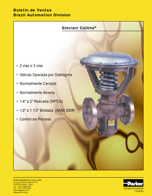
Sinclair Collins ®•2 vias o 3 vias•Válvula Operada por Diafragma •Normalmente Cerrada •Normalmente Abierta •1/4" a 2" Roscada (NPT/G)•1/2" a 1 1/2" Bridada (ANSI 300#)•Control de ProcesoParker Hannifin Ind. e Com. Ltda.Av. Lucas Nogueira Garcez 218112325-900 Jacareí - Brasil Boletín de VentasBrazil Automation DivisionVálvula Roscada - Asiento SuaveCodificaciónOpciónRosca "G" - Agregar el sufijo "BSP" después del código.1/4"3,353,75--C264-000911/4"3,353,75--C284-000713/8"3,053,45--C284-000813/8"3,053,25--C264-001011/4"--4,154,25C264-001113/8"--4,904,25C264-001211/4"3,353,754,154,25C264-001313/8"3,053,454,904,25C264-001411/4"3,353,754,154,25C264-001513/8"3,053,254,904,25C264-001611/2"6,607,30--C264-200111/2"6,607,30--C274-200113/4"8,307,80--C274-200213/4"8,307,80--C264-200211/2"--8,008,00C264-200313/4"--9,9010,80C264-200411/2"6,607,308,008,00C264-200513/4"8,307,809,9010,80C264-200611/2"6,607,308,008,00C264-200713/4"8,307,809,9010,80C264-200811"15,2016,00--C264-400111"15,2016,00--C274-400111 1/4"19,2020,80--C274-400211 1/4"19,2020,80--C264-400211"--19,8023,80C264-400311 1/4"--24,2027,50C264-400411"15,2016,0019,8023,80C264-400511 1/4"19,2020,8024,2027,50C264-400611"15,2016,0019,8023,80C264-400711 1/4"19,2020,8024,2027,50C264-400812"37,5040,00--C274-600511 1/4"30,2028,80--C274-600111 1/2"34,2035,00--C274-600211 1/4"30,2028,80--C264-600111 1/2"34,2035,00--C264-600212"37,5040,00--C264-601711 1/4"--38,5043,00C264-600311 1/2"--38,5044,00C264-600412"--45,5054,50C264-601811 1/4"30,2028,8038,5043,00C264-600511 1/2"34,2035,0038,5044,00C264-600612"37,5040,0045,5054,50C264-601911 1/4"30,2028,8038,5043,00C264-600711 1/2"34,2035,0038,5044,00C264-600812"37,5040,0045,5054,50C264-60201ØConexión CódigoFunciónPresión TrabajoPilotoTemperatura28 bar2,4a 2,8 bar-40°a +204°C2 NA(Conexión en Línea )2 NC (Conexión en Línea )2 NA(Conexión en Ángulo )3 NC 3 NA Cuerpo Básico Cv1-22-12-33-21/4"28 bar2,4a 2,8 bar -40°a +204°C2 NA(Conexión en Línea )2 NC(Conexión en Línea )2 NA(Conexión en Ángulo )3 NC 3 NA 1/2"28 bar2,4a 2,8 bar -40°a +204°C2 NA (Conexión en Línea )2 NC(Conexión en Línea )2 NA(Conexión en Ángulo )3 NC 3 NA 1"28 bar2,4a 2,8 bar -40°a +204°C2 NA (Conexión en Línea )2 NC (Conexión en Línea )2 NA(Conexión en Ángulo )3 NC3 NA1 1/2"OpciónRosca "G" - Agregar el sufijo "BSP" después del código.ØConexión CódigoPresión TrabajoPilotoTemperatura Cuerpo Básico Cv1-22-12-33-21/4"26 bar 34 bar 26 bar 26 bar34 bar 34 bar1/2"34 bar1"31 bar1 1/2"34 bar31 bar31 bar34 bar1/4"2,062,06--C264-00091/4"1,801,85--C284-00073/8"1,952,25--C284-00083/8"2,572,48--C264-00101/4"--2,443,30C264-00113/8"--2,352,62C264-00121/4"2,062,062,443,30C264-00133/8"2,572,482,353,62C264-00141/4"2,062,062,443,30C264-00153/8"2,572,482,353,62C264-00161/2"6,206,30--C264-20011/2"6,106,50--C274-20013/4"7,608,00--C274-20023/4"7,606,80--C264-20021/2"--7,408,80C264-20033/4"--9,6012,00C264-20041/2"6,206,307,408,80C264-20053/4"7,606,809,6012,00C264-20061/2"6,206,307,408,80C264-20073/4"7,606,809,6012,00C264-20081"13,5013,80--C264-40011"13,2012,60--C274-40011 1/4"17,9017,00--C274-40021 1/4"17,2016,50--C264-40021"--17,9018,40C264-40031 1/4"--24,8026,00C264-40041"13,5013,8017,9018,40C264-40051 1/4"17,2017,0024,8026,00C264-40061"13,5013,8017,9018,40C264-40071 1/4"17,2017,0024,8026,00C264-40082"36,0034,70--C274-60051 1/4"31,9029,70--C274-60011 1/2"35,0032,90--C274-60021 1/4"31,9029,70--C264-60011 1/2"35,0032,90--C264-60022"36,0034,70--C264-60171 1/4"--43,2048,50C264-60031 1/2"--45,0049,90C264-60042"--47,3052,00C264-60181 1/4"31,9027,4043,2048,50C264-60051 1/2"35,0031,3045,0049,90C264-60062"36,0034,7047,3052,00C264-60191 1/4"31,9027,4043,2048,50C264-60071 1/2"35,0031,3045,0049,90C264-60082"36,0034,7047,3052,00C264-60202,1a 2,8 bar-40°a +232°C2,1a 2,8 bar -40°a +232°C2,1a 2,8 bar -40°a +232°C2,1a 2,8 bar-40°a +232°CFunción2 NA (Conexión en Línea )2 NC(Conexión en Línea )2 NA(Conexión en Ángulo )3 NC 3 NA 2 NA(Conexión en Línea )2 NC(Conexión en Línea )2 NA(Conexión en Ángulo )3 NC 3 NA 2 NA(Conexión en Línea )2 NC(Conexión en Línea )2 NA(Conexión en Ángulo )3 NC 3 NA 2 NA(Conexión en Línea )2 NC(Conexión en Línea )2 NA(Conexión en Ángulo )3 NC3 NAØConexión CódigoPresión TrabajoPilotoTemperaturaCuerpo Básico Cv1-22-12-33-2FunciónVálvula Bridada - Asiento Duro31 bar 1/2"6,607,30--C264-20011F 1/2"6,607,30--C274-20011F 3/4"8,307,80--C274-20021F 3/4"8,307,80--C264-20021F 1/2"6,607,308,008,00C264-20051F 3/4"8,307,809,9010,80C264-20061F 1/2"6,607,308,008,00C264-20071F 3/4"8,307,809,9010,80C264-20081F 2 NC(Conexión en Línea )1/2"1"15,2016,00--C264-40011F 1"15,2016,00--C274-40011F 1 1/4"19,2020,80--C274-40021F 1 1/4"19,2020,80--C264-40021F 1"15,2016,0019,8023,80C264-40051F 1 1/4"19,2020,8024,2027,50C264-40061F 1"15,2016,0019,8023,80C264-40071F 1 1/4"19,2020,8024,2027,50C264-40081F 1"1 1/2"34,2035,0038,5044,00C264-60061F 1 1/2"34,2035,00--C274-60021F 1 1/2"34,2035,00--C264-60021F 1 1/2"34,2035,0038,5044,00C264-60081F1 1/2"-40°a +204°C-40°a +204°C-40°a +204°C2,4a 2,8 bar 2,4a 2,8 bar2,4a 2,8 bar28 bar28 bar28 bar2 NA(Conexión en Línea )3 NC 3 NA 2 NA(Conexión en Línea )2 NC((Conexión en Línea )3 NC 3 NA2 NA (Conexión en Línea )2 NC (Conexión en Línea )3 NC 3 NAØConexión CódigoPresión TrabajoPilotoTemperaturaCuerpo Básico Cv1-22-12-33-2Función1/2"6,206,30--C264-2001F 1/2"6,106,50--C274-2001F 3/4"7,608,00--C274-2002F 3/4"7,606,80--C264-2002F 1/2"6,206,307,408,80C264-2005F 3/4"7,606,809,6012,00C264-2006F 1/2"6,206,307,408,80C264-2007F 3/4"7,606,809,6012,00C264-2008F 2 NC(Conexión en Línea )1/2"1"13,5013,80--C264-4001F 1"13,2012,60--C274-4001F 1 1/4"17,9017,00--C274-4002F 1 1/4"17,2016,50--C264-4002F 1"13,5013,8017,9018,40C264-4005F 1 1/4"17,2017,0024,8026,00C264-4006F 1"13,5013,8017,9018,40C264-4007F 1 1/4"17,2017,0024,8026,00C264-4008F 1"1 1/2"35,0031,3045,0049,90C264-6006F 1 1/2"35,0032,90--C274-6002F 1 1/2"35,0032,90--C264-6002F 1 1/2"35,0031,3045,0049,90C264-6008F1 1/2"-40°a +204°C-40°a +204°C-40°a +204°C2,4a 2,8 bar2,4a 2,8 bar2,4a 2,8 bar34 bar34 bar34 bar2 NA(Conexión en Línea )3 NC 3 NA 2 NA(Conexión en Línea )2 NC(Conexión en Línea )3 NC 3 NA2 NA (Conexión en Línea )2 NC (Conexión en Línea )3 NC 3 NAVálvula Roscada Cuerpo Básico 1/2"1/4" -NPTA 3 RoscasBCCBBCFD E1231233/4"A B CDEFDimensiones (mm )Rosca (NPT )1/2"Modelo 1/2"3/4"213,6267,549,398,6184,2178,62-vias NAconexión en línea1/8" - NPTA 3 RoscasCBD E123FRosca (NPT )AB C D E F 1/4" o 3/8"169,2127,038,176,2109,5Dimensiones (mm )2-vias NAconexión en ángulo2-vias NC 3-vias NA 3-vias NCVálvula Roscada Cuerpo Básico 1 1/2"1/4" -NPTABC FD1231231/4" -NPTA 3 RoscasBCBCFD E123123A BC D E FDimensiones (mm)Rosca (NPT)1 1/4"2-vias NA conexión en ángulo 3-vias NA 3-vias NC2-vias NC conexión en líneaModelo1 1/2"363,52"467,01 1/4"1 1/2"3192"467,0457,582,6165,1298,4457,52-vias NAconexión en líneaEA BCDEFDimensiones (mm )Rosca (NPT )1"Modelo1 1/4"1"1 1/4"289356,668,3136,6241,32542-vias NA conexión en ángulo2-vias NC 3-vias NA 3-vias NC2-vias NAconexión en línea3 RoscasVálvula Bridada Cuerpo Básico 1/2" - Conexión de 1/2"Válvula Bridada Cuerpo Básico 1/2" - Conexión de 3/4"Válvula Bridada Cuerpo Básico 1" - Conexión de 1"Válvula Bridada Cuerpo Básico 1" - Conexión de 1 1/4"Parker Hannifin Ind. e Com. Ltda.Av. Lucas Nogueira Garcez 2181Esperança Caixa Postal 14812325-900 Jacareí, SPVálvula Bridada Cuerpo Básico 1 1/2" - Conexión de 1 1/2"。
动态平衡电动调节阀(PICV)-Caleffi
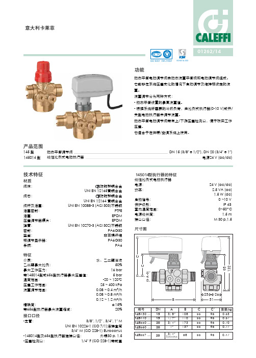
动态平衡调节阀线性比例式电动执行器 DN 15 (3/8” e 1/2”), DN 20 (3/4” e 1”)145014 型电源24 V (ac/dc)ISO 9001 No. 0003意大利卡莱菲功能动态平衡电动调节阀(PICV)145型动态平衡电动调节阀由动态流量平衡阀和电动调节阀组成。
它能够在系统压差变化的情况下自动调节及维持预设定的流量。
流量调节分为两种方式:- 动态平衡设置的最高流量值。
- 根据系统所需要的冷热负荷,由比例式执行器(0-10 V)或开/关型电动执行器来调节流量。
动态平衡电动调节阀带有上/下游压差检测口,便于核实工作压差。
它适合于在供暖/空调系统上使用。
产品范围技术特征材质145 型145014型执行器的特征线性比例式电动执行器电源: 24 V (ac/dc)功率: 2.5 VA (ac) 1.5 W (dc)启动信号: 0 ~10 V 保护级别: IP 43室内温度范围: 0~50°C 电源线长度: 1.5 m 接口口径: M 30 p,1.5尺寸图UNI EN 10088-3 (AISI 303)不锈钢PTFE EPDM EPDMUNI EN 10270-3 (AISI 302)不锈钢PA6G30非石棉纤维PA6G30PA6水、乙二醇溶液50%16 bar 5 bar -20 ~ 120℃25 ~ 400 kPa 0.08 ~ 0.4 m 3/h 0.08 ~ 0.8 m 3/h 0.12 ~ 1.2 m 3/h±15%20%3/8”, 1/2” , 3/4”, 1” MUNI EN 10226-1 (ISO 7/1)活接套筒3/4” M (ISO 228-1) Euroconus外螺30 p. 1.51/4” F (ISO 228-1)带封盖阀体:阀芯:阀杆及活塞:活塞密封:活塞:压差调节器膜片:弹簧:密封:垫圈:预调节显示器:手柄:特征介质:乙二醇最大比例:最大工作压力:带145014型或656型执行器最大压差值:温度范围:压差工作范围:流量调节范围:精确度:带656型执行器最大流量缩减:接口口径-主管:-145014型及656型执行器连接口径:-压差检测口:工作原理Ab)ΔpG 10G (m 3/h)动态平衡电动调节阀(PICV)其控制流量方式为:- 根据其所控制的环路/末端的冷/热负荷自动调节流量大小;- 在系统压差变化的状态下保持流量稳定。
FEL 自由落体消防阀系列及配件说明书

& AccessoriesTable of ContentsFree Fall Fire Valves (Screwed) (3)Maintenance - Free Fall Fire Valves (Screwed) (4)Achieving an Even Operating Torque (4)Maintenance Steps (4)Re-Order Codes for FEL Free Fall Valve Lubricating Grease (5)Free Fall Fire Valves (Flanged) (6)Accessories - Free Fall Fire Valves (9)Fitting Kits (9)Changeover Switches (10)Manual Quick Release (MQR) (11)Electro-Manual Quick Release (EMQR) (13)E-Mag & E-Mag 2 – Electro-Magnetic Quick Release (SQR Type Device) (15)Fusible Links (17)Electro-Thermal Fusible Links (18)Installation - Electro-Thermal Fusible Links (18)Free Fall Fire Valve Control Panel (20)Did you know the following...? .. (21)Free Fall Fire Valves (Screwed)Suitable for installation in either horizontal or vertical pipework.Designed to provide a 100% shut off when used as a fuelisolating valve.May also be used as a fuel ‘dump’ valve, whereby the valvewill open on actuation.Standard Free Fall Valve assembly comprises of a valve,lever, and weight, together with a fitting kit.Standard valves are manufactured in cast iron to ASTMA126 Gr B.Suitable for use with fuel oils at pressures up to 14 bar.Valves with screwed connections have BSP parallel threads.Standard Fire Valves are supplied with a ‘Lubricating Compound’, which is a ge neral-purposesealant, suitable for hydrocarbons.May be actuated mechanically or electrically.Supplied with a Fire Valve Kit, available in sizes, Small (15 to 50mm NB valves), Medium (65to 100mm NB valves) and Large (125 to 200mm NB valves).Kits contain Pulley Wheels, Stainless Steel Cable, Fusible Links (Standard 72 Degrees),Warning Signs, Cable Connectors and Tension Springs, any of which may be purchased as individual products.Electrically actuated Fire Valve systems utilise a standard valve, lever and weight and use anE-MAG Electro-Magnetic Release System, allowing actuation by making or breaking an electrical circuit, usually 24V DC or 230V AC.The installation of a valve mounted changeoverSwitch, Electro Mechanical Release or WallMounted Changeover Switch may provide remotesignalling of the Fire Valve status or allow directswitching of electrical equipment where applicable.Competitively priced with a full range of ancillaries.Available Sizers are below –Email– ******************* Web - Tel- 00 44 (0)1565 733137 P a g e | 4 Maintenance - Free Fall Fire Valves (Screwed)Frequent maintenance of your Free Fall Fire Valve is strongly advised. We recommend that the valve is inspected every 3 month s. The Fire Valve will need to be ‘re -charged withlubricating grease’ throughout its life. Frequency of re-charging depends on several aspects: flow rate, valve usage, pressure and temperature. FEL Lubricating Grease is supplied in ‘Stick Form’ and can be inserted into the valve spindle without a grease gun. During inspection, attention should be paid to the ‘Combination Screw’ and how far it is screwed into the valve spindle. The Combination Screw is fitted into the valve spindle and is used to insert lubricating grease into the aperture between the valve body and plug valve by turning until resistance is felt. If the Combination Screw is fully screwed into the valve spindle, this indicates that the valve needs to be re-charged with lubricating grease. Lack of lubricating grease may be the cause of fuel leakage, or, if the valve is fitted to the suction side of a fuel pump, it may allow air to enter your fuel system. Each FEL Free Fall Fire Valve is supplied complete with a Maintenance Record Card at the time of purchase. The Maintenance Card will provide a record of the installation date and ongoing routinemaintenance as well the original FEL Order Reference. This is an important record for the end customer and will help to keep the valve in a serviceable condition throughout its life.Achieving an Even Operating TorqueShould a valve become jammed or unusually stiff to operate, this can usually be cured by the injection of lubricant. If this is ineffective it will be necessary to dismantle the valve, clean the components and recharge with lubricant. Please contact us for more information.Maintenance Steps1. Visually inspect the valve for damage and leakage.2. Release the stainless-steel cable and work the valvelever for several strokes, the valve plug should rotate evenly backward and forward.3. The combination screw is used to force lubricatinggrease into the valve body.Before it has reached its limit (Fully ScrewedDown), the Combination Screw should be removed, a grease stick should then be inserted into the aperture in the valve spindle.Replace the combination screw, remember to re-attach the Maintenance Record Card.*Mainten ance Card(Always leave attached to the valve Body)4.Tighten the Combination Screw until some resistance is felt. Give several steady strokes of thelever to distribute the lubricant. Ensure the lever moves evenly. This may need repeating.5.The first indication of the valve becoming fully charged is an increase in rotate the combinationscrew and/or an increase in effort required to rotate the lever.6.Should grease appear between the valve body and plug, this indicates the valve is overcharged.7.When the correct even operation of the valve is achieved, re-attached the stainless-steel cable.8.Inspection and re-charging should be carried out every 3 months to ensure correct operation ofthe valve.Re-Order Codes for FEL Free Fall Valve Lubricating GreaseTo re-order the lubricant, you can use code number –20-050 followed by the quantity of grease sticks you require –Free Fall Fire Valves (Flanged)Suitable for installation in eitherhorizontal or vertical pipe work. Designed to provide a 100% shut offwhen used as a fuel isolating valve. May also be used as a fuel ‘dump’ valve, whereby the valve will open onactuation. Standard Free Fall Valve assembly comprises of a valve, lever and weight all finished in RAL 3000 Flame Red, togetherwith a fitting kit. Suitable for use with fuel oils and gasesat pressures up to 14 bar. The double Viton O ring stem seals makethe valve ideal for pump suction lines.Valve connections are flanged to BS 4504 PN16 or ANSI CL. 150Valves may be actuated mechanically or electrically.Fire Valve Open/Close status signals are available for all valves. We have a wide range of ancillary signalling switches.Free Fall Fire Valve Set Up (Mechanical)Free Fall Fire Valve – Kit Components20-107 Caution Sign & Maintenance Card 20-101 Tension Spring20-080 316 Stainless Steel Cable 20-110 Cable Connectors20-070/M6 M6 Pulley Assembly, 40mm Diameter c/w Backplate 20-074/M6 M6 Brass Anchor c/w Backplate 20-077/M6 M6 Backplate 20-110 Cable ConnectorsFree Fall Fire Valves (Screwed)20-001 ½” 20-003 ¾”20-005 1” 20-007 1 ¼” 20-009 1 ½” 20-0112”Release Mechanisms20-160 Manual Quick Release20-161 Electro-Manual Quick ReleaseSpare Free Fall Fire Valve Kits20-060 “Small” for ½” to 2” Valves 20-061 “Medium” for “2 ½” to 4” Valves20-062“Large” for 5” to 8” ValvesElectro Magnetic Valve Release Mechanisms20-162 24V DC Emag 20-163 110V AC Emag 20-164 230V AC Emag20-165 24V DC Emag2 c/w Volt Free Contacts 20-166 110V AC Emag2 c/w Volt Free Contacts 20-167230V AC Emag2 c/w Volt Free ContactsLubricant for Free Fall Fire Valves20-050/4 Lubricant, Diesel fuel x 4 Sticks 20-050/8 Lubricant, Diesel fuel x 8 Sticks 20-050/12 Lubricant, Diesel fuel x 12 Sticks 20-050/16 Lubricant, Diesel fuel x 16 Sticks 20-050/24 Lubricant, Diesel fuel x 24 Sticks 20-050/32Lubricant, Diesel fuel x 32 SticksProduct Code (Light Duty)Temperature ofLinksMax Load20-090 72°C 161F 30lb 20-091 92°C 197F 30lb 20-092 103°C 217F 30lb 20-093 127°C 260F 30lb 20-094 143°C 289F 30lb 20-095183°C361F30lbProduct Code (Heavy Duty)Temperature ofLinksMax Load20-090/HD 72°C 161F 40Kg 20-091/HD 92°C 197F 40Kg 20-092/HD 103°C 217F 40Kg 20-093/HD 127°C 260F 40Kg 20-094/HD 143°C 289F 40Kg 20-095/HD183°C361F40KgChangeover Switches20-150Changeover Switch - Single Phase 10 amp 20-151Changeover Switch - Three Phase 10 ampFree Fall Fire Valve Set Up (Electrical)Email – ******************* Web - Tel- 00 44 (0)1565 733137 P a g e | 8Fire Valve Control Panels20-180 240V AC Fire Valve Control Panel with Changeover and Facility 20-181 24V DC Fire Valve Control Panel with Changeover and Facility 20-182 110V AC Fire Valve Control Panel with Changeover and Facility 20-183240V AC Fire Valve Control Panel with 24V DC Outputs & chargerEmail – ******************* Web - Tel- 00 44 (0)1565 733137 P a g e | 9 Accessories - Free Fall Fire ValvesFitting KitsEach Free Fall Fire Valve purchased comes with a fitting kit.Small Kit, 20-060for 15 to 50mm Valve Sizes Medium Kit, 20-061for 65 to 100mm Valve Sizes Large Kit, 20-062 for 125 to 200mm Valve SizesFitting Kits - Free Fall Fire Valves Medium Kit Contents 20-061Large Kit Contents20-062Changeover SwitchesValve mounted changeover switchesprovide position status via a robust voltfree changeover switch, rated to 230V 10amps, allowing direct switching of pumpsor relays upon valve actuation.Single phase mercury switch assemblieshouse one single pole changeover switch,whilst three phase installations have threeSPCO switches, housed within oneenclosure.The SPCO switch is a steel encased mercury switch, potted within a dielectric resin andencapsulated within a sealed terminal enclosure, which in turn, is fixed within a grey ABS valvemounted housing. The switching action is generated by valve closure. As the valve lever travelsfrom 45 degrees above the horizontal plane of the pipe to 45 degrees below the pipe, althoughboth single and three phase versions can also be used with vertically mounted Free Fall FireValves.An alternative switch assembly is also available, ideal for water industry applications or wherethe use of mercury as a switching media is not authorised.All Free Fall Fire Valves manufactured by FEL have pre-drilled levers to accept retrofittedchangeover switches.Open PositionClosed PositionEmail –******************* Web - Tel- 00 44 (0)1565 733137 P a g e | 10Designed for use with ‘fusible link operated free fall fire valve’Provides manual release of fire valve systemCan be used with electro-mechanical fire valve Systems40mm red push button operationIntegral shroud to prevent accidental operationBrass release spindle and 40mm pulley wheel assemblyWall or generator enclosure mountingOptional 24v DC volt free changeover switchOption Red/Green LED’s for status indicationThe Manual Quick Release (MQR) is designed for use with fusible link actuated fire valves.In operation, the MQR provides manual activation of the fire valve system. Pressing the redpush button will release the fire valve cable tension, allowing the valve to close by gravity.The MQR is usually sited adjac ent to an ‘Exit’ doorway in a plant room or generator enclosure and is particulary useful for testing fire valve systems as well as providing manual fire valve closure in an event whereby an operator observes something of concern and doesnot want to wait for a fusible link to melt, triggering valve closure.The MQR can also be used in conjunction with a wall mounted FEL E-Mag or E-Mag2 electro-magnetic fire valve release. This combination provides fire valve release options by fusible link, MQR manual operation and also electrically using an E-Mag via a fire alarm interface.Release Mechanisms20-160Manual Quick Release20-161Electro-Manual Quick ReleaseEmail– ******************* Web - Tel- 00 44 (0)1565 733137 P a g e | 13 Electro-Manual Quick Release (EMQR)Designed for use with fusible link actuated fire valves.Provides manual activation of the fire valve system by pressing the red push button. Automatically senses the release of tension on the stainless-steel fire valve cable.Internal volt free change over switch changes status, de-energising the ‘Load’ terminal energisi ng the ‘Alarm’ output terminal. Safety shroud included.In operation, the EMQR provides manual activation of fire valve system by pressing the red push button, or, it can automatically detect when a fusible link has melted bysensing the release of tension on the stainless-steel fire valve cable. In either event, an internal volt free changeover switches changes status, de-energising the ‘Load’ terminal energizing the ‘Alarm’ output terminal.When tension is applied to the stainless-steel fire valve cable, this will upwardly extend the spring loaded, removable spindle housed within the EMQR. By doing this, the ‘Load’ terminal is energised and th e Green ‘Load Circuit’ lamp is illuminated. Release of tension or pressing the red push button will contract or release the spring-loaded spindle and the Red ‘Alarm Circuit’ lamp is illuminated whilst turning off the ‘Load’ lamp.Release Mechanisms20-160 Manual Quick Release20-161Electro-Manual Quick ReleaseEmail– ******************* Web - Tel- 00 44 (0)1565 733137 P a g e | 15 E-Mag & E-Mag 2 – Electro-Magnetic Quick Release (SQR Type Device)The E-Mag and E-Mag2Electromagnetic quick release mechanisms are for use with electrically actuated fire valvesystems. They provide instant release of Free Fall Fire Valves when de-energised, making them the ideal method for remote fire valve closure. The E-Mag is a standardelectromagnet, which will de-magnetise on loss of power, the E-Mag2 version has inbuilt auxilliary volt free changeover contacts, which signal valve status.Both E-Mag and E-Mag2 may b e installed as ‘wall mounted’ or ‘direct mounted’.Wall mounted E-Mag or E-Mag2 installations can be designed to release a stainless steel fire valve cable, which can be used in the normal way with pulley wheels and fusible link, by using an interface which will isolate a fuel supply in the event of a Fire Alarm or other means of control input by de-energising the electromagnet. Similar to the way in which anautomatic fire door closes in the event of a building fire alarm. However, the system still incorporates a fusible link, providing a mechanical means of fire valve shut off as well as electrical control.Open PositionDirect mounting installations have the E-Mag or E-Mag2 sited directly above the fire valveand do not incorporate a fusible link in the system, but rely upon electrical control only. Both E-Mag & E-Mag2 version include a ‘Push to test’ facility and have 40Kg electromagnetic holding power as standard.Wall mounted E-Mag or E-Mag 2 Electromagnetic Release used with soldered fusible link for electrical control with mechanical fusible link local fire protectionClosed PositionFusible LinksFusible links are made in a range of sizes and temperatures using high quality brass pressings and low melting point alloys.A range of fusible links, manufactured from formed brass leaves, soldered using eutecticsolder, each fitted with zinc plated steel ‘S’ hooks for ease of installat ion within a fire valvesystem.The use of eutectic solder, as opposed to a ranged solder, gives rise to greater accuracy atthe actual fuse temperature.Available as a “Light Duty Link”, with static loading up to 13KgA vailable as a ‘Heavy Duty Link’, with 45Kgmaximum weight strain rating.Customised versions also available.`Product Code(Light Duty)Temperature ofLinksMaxLoad20-09072°C 161F 13Kg20-09192°C 197F 13Kg20-092103°C 217F 13Kg20-093127°C 260F 13Kg20-094 143°C 289F 13Kg20-095 183°C 361F 13KgProduct Code(Heavy Duty)Temperature ofLinksMaxLoad20-090/HD72°C 161F 45Kg20-091/HD92°C 197F 45Kg20-092/HD103°C 217F 45Kg20-093/HD127°C 260F 45Kg20-094/HD 143°C 289F 45Kg20-095/HD 183°C 361F 45KgElectro-Thermal Fusible LinksElectro Thermal Link contains a fuse which melts whenexcessive ambient temperature is detected breaking thepower supply to safety valves.Electrical Rating: 10A, 230VACFuse melts at desiEnclosure: IP30Installation - Electro-Thermal Fusible LinksThe unit should be fitted between 0.3 to 1.3m directly above the potential fire hazardwith the slotted lid facing downloads.Can be suspended by metal conduit.The ventilation holes in the box must not be covered.Allow free unrestricted airflow through the enclosure.Electro ThermalFusible LinksTemperature ofLinks20-17072°C 161F20-17184°C 183F20-17296°C 204F20-173121°C 249F20-174 167°C 332F20-175 184°C 363FFree Fall Fire Valve Control PanelThe FEL Fire Valve Control Panel is used to maintain power to an E-MAG or SQR type device.Power Output is 24V DC, with 230V Input24V DC Units are battery backed and designed tomaintain power output in the event of mains failurewhilst continuing to provide fire detection throughelectro-thermal links or normally closed emergencypush buttons wired in seriesBattery backup time and battery size is calculated onthe required load to maintain multiple E-Mag,Motorised Valves or SQR type devicesBMS connectivity via volt free contactsInside the Panel Inside of the Panel(Door)Did you know the following…?We also supply -Float SwitchesFill Point, Level Gauges, ControlsMotorised Valves (Fail Safe)Pumps & PanelsFuel PolishersEmail –******************* Web - Tel- 00 44 (0)1565 733137 P a g e | 21。
卡莱菲减压阀样本 冷热水系统元件 图册

7
此图仅为示意图
减压阀 减压稳压阀 高温减压阀 筒式过滤器 防水锤阀 BALLSTOP 止回球阀 LEGIOMIX 热力杀菌电子恒温混合阀 LEGIOFLOW 多功能水路组件 恒温混合阀 恒温平衡阀 单向泄压阀 温度/压力安全阀 生活热水膨胀罐 限流阀 箱式预组装生活冷热水分水器 防冻元件
5334
卡莱菲倾斜式减压阀
阀芯及滤网可抽取可更换 阀体:黄铜镀铬 耐压:16 bar 出水可调压力:1 ~ 6 bar 耐温:40℃ 带压力表接口1/4" F
样本 01024
编号 533441 533451 533461
口径 1/2" 3/4" 1"
5330
卡莱菲减压阀阀芯及滤网
适合于5330、5331、5332和5334型减压阀 编号 533000
卡莱菲过滤网
适合于5370筒式过滤器10" 最大压差:3 bar 耐温:5 ~ 40℃ 537004 - 60 μm 织布网 537005 - 50 μm 不锈钢网
编号 537004 537005
防水锤元件
525
样本 01020
ANTISHOCK
防水锤阀
阀体:黄铜镀铬 耐压:10 bar 耐温:90℃ PTFE密封
119
可视调节型减压阀
5350
样本 01085
卡莱菲可视调节型减压阀
可抽取式一体阀芯 带预调节显示器 阀体:防脱锌铜 耐压:25 bar 出水可调压力:1 ~ 6 bar 耐温:40℃ EN 1567认证 带压力表0 ~10 bar
7
5350
样本 01085
意大利卡莱菲流量平衡阀130型说明书
意大利卡莱菲流量平衡阀130型功能静态流量平衡阀运用于水力系统,它精确地平衡系统每个支路或者每个末端的流量。
循环系统的平衡是保证系统按设计工况正确运行的前提,只有在此前提下系统才能提供最大的热舒适度、最大限度地降低能耗。
螺纹连接型的平衡阀阀体内部采用文氏流量计,使流量调节更精确、流量检测更方便。
产品范围130型 文氏流量计型流量平衡阀,螺纹连接型 口径 :DN 15 (1/2"), DN 20 (3/4"), DN 25 (1"), DN 32 (1 1/4"), DN 40 (1 1/2"), DN 50 (2")130 型 流量平衡阀,法兰连接型 口径:DN 65, DN 80, DN 100, DN 125, DN 150, DN 200, DN 250, DN 300130型 文氏流量计型平衡阀配套保温壳保温壳的构造特征材质材质: PE-X 密封发泡厚度: 15 mm 密度: -内部:30 kg/m3 -外部:80 kg/m3导热系数(ISO2581): - 0℃:0.038 W/(m•K)- 40℃: 0.045 W/(m•K)湿阻因子(DIN52615): >1,300工作温度范围: 0~100℃防火等级(DIN4102): B2级尺寸图130060 130080 130100 130120 1301501315.5213245 ADN 65DN 80DN 100DN 125DN 150B290310350400480C225235245350380130200 130250 130300115160210 DN 200DN 250DN 300600730850480525535编号重量 (kg)系统平衡的优点经过流量平衡的系统其主要优点如下:1. 系统的末端在供暖、制冷及除湿状态下正常工作,不会造成能源浪费,舒适度得到保证。
Caleffi 温暖系统控制器说明书
© Copyright 2022 Caleffi • Portare la valvola in chiusura• Predisporre il contagiri in posizione 0-0 (3)• Orientare il volantino con il perno anti-rotazione (4) sul corpo• Infilare il volantino sullo stelo• Serrare la vite di fermo (1)• Set the valve to its closed position• Set the rev counter to position 0-0 (3)• Position the handwheel with the anti-rotation pin (4) on the body• Slide the handwheel onto the stem• Tighten the locking screw (1)• Placer la vanne en position de fermeture• Mettre le compte-tours en position 0-0 (3)• Orienter la poignée avec le pivot anti-rotation (4) sur le corps• Enfiler la poignée sur la tige• Serrer la vis de blocage (1)•• Rimuovere la vite di fermo (1)•Sfilare il volantino (2) dallo stelo •Set the valve to its closed position •Remove the locking screw (1)•Slide the handwheel (2) off the stem •Placer la vanne en position de fermeture •Dévisser la vis de blocage (1)• Extraire la poignée (2) de la tigeMontaggio Fitting Montage Smontaggio RemovalDémontage Cod. F0001911ISTRUZIONI PER L’INSTALLAZIONE E LO SMONTAGGIO MANOPOLAKNOB INSTALLATION AND REMOVAL INSTRUCTIONSINSTRUCTIONS POUR L’INSTALLATION ET LE DÉMONTAGE DE LA POIGNÉE Manopola di ricambio per valvola di bilanciamento manualeCodice: 130063/130083/130103/130123/130153Spare knob for manual balancing valveCode: 130063/130083/130103/130123/130153Poignée de rechange pour vanne d’équilibrage manuelCode: 130063/130083/130103/130123/130153IT FREN Manufactured by BRANDONI via Novara n 19928078 Romagnano Sesia, NO, Italy。
《自动排气阀》使用说明书 v2.1
《自动排气阀》使用说明书一、产品概述气系统及暖通空调系统的运行过程中,水在加热时释放的气体(如氢气、氧气等)带来的众多不良影响会损坏系统及降低热效应,这些气体如不能及时排掉会产生很多不良后果。
诸如:由氧化导致的腐蚀;散热器里气袋的形成;热水循环不畅通不平衡,使某些散热器局部不热;管道带气运行时的噪声;循环泵的涡空现象。
由此可见运用自动排气阀的重要作用。
上海沪航铜业阀门制造有限公司的新型排气阀设计考虑了己知的所有不利因素,(如水中的杂质、油、悬浮物等、排气时阀内液体产生的动荡;排气阀所连接的管道和设备的振动等。
)具有优良的性能:不管是在系统刚加水运行(系统刚运行时,有大量的气体排出。
)还是在系统压力过高需适度排水卸压时,都能可靠运行。
二、产品特点1.性能可靠。
排放装置材料使用PK-EP。
和所有已知的合成材料相比,PK-EP有最好的性能和最高的可靠性。
PK-EP能承受高温(比排气阀.的工作温度高很多)。
O型密封圈使用优化材料EPDM,保证在高温下O型密封圈仍然有良好的弹性和运行可靠性。
排气阀阀芯的内部弹簧采用特殊的材料,并采用镀镍不锈钢,防止氧化(如果氧化会影响阀芯的运动);排气阀的排气机制非常可靠,在出厂前每只阀均通过排气实验和压力密封实验。
阀体和阀盖用HPb59-1黄铜热锻造,组件优质黄铜造而成,从而得到完美的装配。
2.维修方便。
自动排气安装有H18阻断阀,H18阻断阀允许方便的从系统上卸下排气阀进行维护,而系统中的水不会流出,所以不必排空系统。
3.只排气,不排水。
汽、水分离盘设计采用特殊的结构,保证排气时绝不排水。
4.只要系统有压力,排气阀就会连续不断的排气。
三、主要用途自动排气阀用于:独立采暖系统;集中供热系统;地板辐射采暖系统;太阳能采暖系统;热泵系统;中央空调;采暖锅炉等。
四、自动排气阀的工作原理当系统中有空气时,气体聚集在排气阀的上部,体内气泡堆积使浮球随水位下降,因此打开排气活塞;气体排尽后,水位上升,浮球也随之上升,关闭排气活塞。
Caleffi S.p.A 542 系列温度抗压阀说明书
replaces dp 01001/18 ENTemperature relief valve certified and calibrated to INAIL standards542 seriesGeneralThe temperature relief valves are made by Caleffi S.p.A. in compliance with the essential safety requirements laid down by Directive 2014/68/EU of the European Parliament and the Council of the European Union for harmonisation of member states with regard to pressurised equipment.FunctionThe temperature relief valves are used in heating systems to discharge water from the system when the set temperature is reached. The valves have positive action, which means that they will always work, even if the sensitive element fails.Technical specifications Materials Body:brass EN 12165 CW617NActuator stem: brass EN 12164 CW614NObturator seal: EPDM Seals: EPDMSprings:stainless steelProtective cover:PPPerformance Medium: waterPED category: IVWorking pressure: 0,3 ≤ P ≤ 10 barSetting temperature: - 1 1/2” x 1 1/4”: 98 °C- 1 1/2” x 1 1/2”: 99 °COperating temperature range:5–100 °CAuxiliary microswitch contact rating: 15 AThreaded connections: 1 1/2” M x 1 1/4” F1 1/2” M x 1 1/2” FReference standardsAccording to the provisions of Collection R Ed. 2009, technical application specifications of Heading II of Italian Ministerial Decree 1/12/75 regarding central heating systems using hot water with temperatures no greater than 110°C and a maximum nominal heat output from the firebox (or maximum total heat capacity of the firebox) greater than 35 kW, a temperature relief valve must be used in the following cases:Open vessel systems - Systems with generators supplied with non-pulverized solid fuel, in place of the consumption water heater or emergency heat exchanger (Chap. R.3.C., point 2.1).Closed vessel systems- Systems with closed expansion tanks (Chap. R.3.B., point 1, letter b).- Heating systems with generators supplied with non-pulverized solid fuel (Chap. R.3.C., point 3.2) not including “assemblies” (pressure equipment provided by the manufacturer as an integrated functional assembly) covered by point C, paragraph 2, art. 3 of Italian L egislative Decree 25.02.2000 no. 93 (implementation of the 2014/68/EU - PED Directive). For systems with nominal powers up to 100 kW and partial cut-off, the residual power dissipation device may consist of temperature relief valves alone.- Systems with heat exchangers whose primary circuits are supplied with a medium at temperatures above 110°C (Chap. R.3.D., point 2.2.1, letter g)).- Direct contact water heaters for domestic and technological use (Chap. R.3.E.). Follow the requirement of Chap. R.3.B..- Systems with modular heat generators (Chap. R.3.F . point 2.2). In addition to the requirements of point 2.1, unless they are installed inside the outer jacket, the safety, protection and control devices, including the expansion system referred to in Chap. R.3.A. and Chap. R.3.B., must be installed on the flow pipe, immediately after the last module and no more than 1 m from the jacket, as long as the temperature and pressure in the single modules does not exceed the respective rated values.- Solar panel systems (Chap. R.3.H., point 3.2.2., letter C)). See 542 SOL series (Tech. broch. 01244).Operating principleA temperature-sensitive element (1), immersed directly in the system medium, acts on the obturator (2) of the valve.On reaching the set temperature, the valve opens and discharges the water from the system.The obturator movement actuates an electric switch (3), which can be used to stop the fuel supply to the burner or to turn on the refilling device.The obturator position, and therefore the valve flow rate, vary according to the temperature of the medium. On reaching the set closing temperature, the valve closes automatically.Moreover, the valves have positive action, which means that they will always open the drain, even if the sensitive element fails.EU-Type Examination - Production Type CertificateEU-Type Examination - Production Type CertificateCollection R Ed. 2009The provisions of point 7, chapter R.2.A of Collection R Ed. 2009, further reiterated by INAIL circular no. 1539 of 11 March 2011, establish that safety devices certified according to Directive 2014/68/EU (PED) shall be accepted automatically for the use covered by the Collection.Also pursuant to Collection R Ed. 2009, such devices, and therefore also temperature relief valves, must be accompanied by the following documents: manufacturer’s certificate and bench calibration report.The manufacturer’s certificate is a document that provides the technical specifications of the valve, which are derived from testing carried out during certification.The manufacturer’s certificate also contains details of the certification document.Each part in the series covered by the manufacturer’s certificate, manufactured in the period for which the PED certification is valid, is certified indefinitely (there is no expiry date).The bench calibration report is a document that attests that the set temperature was tested for each single temperature relief valve.This check is carried out in the presence of an INAIL official, who draws up and signs the report following a successful outcome.The report indicates the serial number of the valve, which is also given on a plate secured to the valve body.There is only one copy of the report, so it must be kept together with the valve.CertificationCE MarkThe 542 series temperature relief valves meet the requirements of Directive 2014/68/CE for pressurised equipment (also referred to as PED). They are therefore classified as category IV and are CE marked. Moreover, the electrical components comply with the requirements of Directive 2014/35/EU.Certified CE markManufacturer’s certificateBench test report00Operating specificationsThe following are average results from the qualification tests and are given on the certificates issued by INAIL:- temperature setting, at which the valve starts to open:- discharge temperature, at which the nominal flow rate occurs:- closing temperature, at which the valve closes as the temperature drops:- emergency trip temperature, at which the valve starts to open if the thermostatic element fails (positive action):- d ischarge flow rate given by the graph that accompanies each valve, from the equation G= Kv · Δp n where Gis the flow rate in l/h of water at a temperature of t1, discharged by the valve;Kv is the valve flow coefficient, i.e. its characteristic nominal flow, equal to: (the value given is the smallest among those measured during normal operation Kv N and during positive action Kv E with Δp = 1 bar, values derived from the manufacturer’s certificate). The following definitions apply: - N ormal flow coefficient Kv N : the valve flow rate in l/h at the discharge temperaturewith a pressure difference of 1 bar at the drain. - E mergency flow coefficient Kv E : the valve flow rate in l/h at the emergency triptemperature with a pressure difference of 1 bar at the drain.Δp is the different in pressure before and after the valve. If there is refilling, Δp hydrostatic pressure at the point in which the valve is installed, otherwise, Δp is given a conventional set value of 0,5 bar;n is the exponent of the variable Δp and has a value of:- heat flow P without refilling:-flow rate without refilling (Kv= Kv E , Δp=0,5 bar)t o = 98 °C t o = 99 °C t 1= 104 °C t 1= 99°C t 2= 95 °Ct 2= 96 °Ct E = 99 °C t E = 98,5 °C6.100 l/h 20.300 l/h6.650 l/h 21.600 l/h 6.100 l/h20.300 l/h0,382 0,495136 kW 419 kW(117.000 kcal/h)(360.100 kcal/h)4.680 l/h14.404 l/h1 1/2” x 1 1/4” 1 1/2” x 1 1/2”SizingFor sizing, refer to Collection R Ed. 2009, chap. R.2.A., point 3 and related sub-points indicated in brackets.With refillingIf there is total refilling from the water mains the following formula is used to calculate the discharge flow rate, unless using an autoclave (point 3.7.1):G = P/0,093Discharge flow rate [l/h]where P is the nominal heat power of the generator expressed in kW. This flow rate value must not be higher than that obtained from the temperature relief valve diagram at the effective system operating temperature, or using the formula G = Kv · Δp n .Partial or no refillingCollection R Ed. 2009 considers partial refilling to be the same as no refilling (point 3.7.2.).The discharge flow rate is calculated as:G = P/0,029Discharge flow rate [l/h]where P is the nominal heat power of the generator expressed in kW with an assumed conventional pressure of 0,5 bar.This flow rate value must not be higher than that obtained from the temperature relief valve diagram at a discharge pressure of 0,5 bar, or using the formula G = Kv · Δp n , with a discharge pressure of 0,5 bar.Electric connections1. solenoid valve on the fuel supply;2. burner;3. possible motorised valve to supply the refilling water;4. audible and/or visible alarm (5).Discharge pipeSince the temperature relief valve is built to discharge significant water flow rates, considering the pressures involved, it is valve outlet.operation and must not endanger people or things.In accordance with applicable regulations, the temperature relief valve drain must be visible and piped using suitable collection pipes.542 seriesTemperature relief valve certified and calibrated to INAIL standards. CE marked in accordance with directives 2014/68/EU and 2014/35/EU. With positive action. 1 1/2” M x 1 1/4” F (1 1/2” M x 1 1/2” F) threaded connections. Brass body. Stainless steel springs. EPDM seals. PP protective cover. Medium: water Complete with 4-wire cable and electric changeover switch with manual reset. Microswitch auxiliary contact rating 15 A. Operating temperature range 5–100 °C. Temperature setting at which the valve starts to open 98 °C (1 1/2” x 1 1/4”), 99 °C (1 1/2” x 1 1/2”). Maximum operating temperature 10 bar.SPECIFICATION SUMMARYCaleffi S.p.A.S.R. 229 n. 25 · 28010 Fontaneto d’Agogna (NO) · Italy Tel. +39 0322 8491 · Fax +39 0322 863723****************·© Copyright 2023 CaleffiWe reserve the right to make changes and improvements to the products and related data in this publication, at any time and without prior notice.The website always has the most up-to-date version of the document, which should be used for technical verifications.。
- 1、下载文档前请自行甄别文档内容的完整性,平台不提供额外的编辑、内容补充、找答案等附加服务。
- 2、"仅部分预览"的文档,不可在线预览部分如存在完整性等问题,可反馈申请退款(可完整预览的文档不适用该条件!)。
- 3、如文档侵犯您的权益,请联系客服反馈,我们会尽快为您处理(人工客服工作时间:9:00-18:30)。
口径 3/8" M 1/2" M 无PTFE密封
编号 502730
2
5024
样本 01033
ROBOCAL
卡莱菲自动排气阀
阀体:黄铜 耐压:10 bar 最大排气压力:4 bar 耐温:115℃
口径 1/4" M 3/8" M
5025
样本 01033
ROBOCAL
卡莱菲自动排气阀
阀体:黄铜 耐压:10 bar 最大排气压力:4 bar 耐温:110℃ 带自闭阀
口径 3/4" 1" 1 1/4" 1 1/2" 2"
551 DISCAL
样本 01060
卡莱菲垂直管道安装式微泡排气阀
阀体:黄铜 内螺连接 耐压:10 bar 最大排气压力:10 bar 耐温:0 ~ 110℃
编号 551905 551906
口径 3/4" 1"
口径 3/8" M
包装 50
5026
样本 01033
ROBOCAL
卡莱菲自动排气阀
阀体:黄铜 耐压:10 bar 最大排气压力:6 bar 耐温:115℃
口径 3/8" M 1/2" M
5027
样本 01033
ROBOCAL
卡莱菲自动排气阀忧
阀体:黄铜 耐压:10 bar 最大排气压力:6 bar 耐温:110℃ 带自闭阀
一个系统中可分离及排除的气体量与系统的流速和压力相 关,当流速和压力降低时排气量也随之上升。
在系统按可允许最高流速循环25次后,几乎所有的空气均 从微泡排气阀中排除,排气比例因系统压力不一而略有区别。
剩余的少量气体将在系统接下来正常循环中排除。在流速 更低或温度更高的情况下,排气量还将更高。
32
编号 551050 551060 551080 551100 551120 551150 551052 551062 551082 551102 551122 551152
样本 01056
5081
样本 01056
卡莱菲吸湿阀芯
适用于5080型吸湿排气阀
口径 12 p,1.5
337
卡莱菲泄水阀
排水方向可调节 阀体:黄铜 螺纹PTFE密封 耐压:6 bar 耐温:85℃
口径 1/4" 3/8"
337
卡莱菲泄水阀
排水方向可调节 阀体:黄铜 螺纹PTFE密封 耐压:10 bar 耐温:100℃
卡莱菲551型微泡排气阀针对以上问题设计,能连续有效地 自动排除系统内存在的微泡气体。
微泡排气阀有螺纹连接、法兰连接及焊接三种连接方式。微 泡排气阀外层配备保温壳,能适合于供暖及制冷的隔热需求。
低压损
DISCAL型垂直安装式微泡排 气阀其特殊内部构造保证大流量 下的低压损。它适合于多种闭式 循环的水路系统。
5020
样本 01054
MINICAL
卡莱菲自动排气阀
阀体:黄铜 耐压:10 bar 最大排气压力:2.5 bar 耐温:120℃ 带吸湿排气帽
编号 502130 502140
口径 3/8" M 1/2" M
编号 502050 502060
28
口径 3/4" M 1" M
编号 502131 502141
2
551
样本 01060
DISCAL
卡莱菲法兰连接式微泡排气阀
主体:碳钢,防锈漆处理 PN 10 法兰连接 对接法兰 EN 1092 - 1 耐压:10 bar 最大排气压力:10 bar 耐温:0 ~ 110℃ 温感接口口径:1/2" 内螺
它的创新设计保证了无论哪 个水流方向其排气效果都不会受 到影响。
卡莱菲保温壳
适用于551型微泡排气阀
编号 CBN551005 CBN551007 CBN551009
适合型号 551005 - 551006 551007 - 551008 551009
空气分离效率
DISCAL型微泡排气阀以连续的方式排除水路系统中存在的 气体,其微泡分离能力强。
卡莱菲自闭阀
阀体:黄铜 适于5020型自动排气阀 PTFE密封 耐压:10 bar 耐温:110℃
口径 3/8" M 3/8" F × 1/2 " M 1/2" M
无PTFE密封
编号 502630 502640
561
样本 01054
卡莱菲自闭阀
阀体:黄铜镀铬 适于5020及5022型自动排气阀 PTFE密封 耐压:10 bar 耐温:110℃
样本 01055
卡莱菲散热器直角自动排气阀
阀体:黄铜镀铬 耐压:10 bar 最大排气压力:2.5 bar 耐温:100℃ 带吸湿排气帽
现货供应卡莱菲产品
服务电话:18611167398
口径
1/2" M
3/4" M
1" M
正扣
1" M
反扣
5620 AQUASTOP
样本 01054
卡莱菲镀铬吸湿排气帽
编号 337221 337231
口径 1/4" 3/8"
560
样本 01056
卡莱菲散热器泄水阀
阀体:黄铜镀铬 耐压:10 bar 耐温:100℃
编号
口径
560421* 560000
1/2" 泄水橡胶软管
* 10个泄水阀包含1个泄水橡胶软管
31
2
编号 551004
编号 551003
服务电话:18611167398
口径
DN 50
不带保温壳
DN 65
不带保温壳
DN 80
不带保温壳
DN 100 不带保温壳
DN 125 不带保温壳
DN 150 不带保温壳
DN 50
带保温壳
DN 65
带保温壳
DN 80
带保温壳
DN 100 带保温壳
DN 125 带保温壳
DN 150 带保温壳
编号 551200 551250 551300
卡莱菲吸湿排气帽
适用于507型排气阀
编号
R59720
样本 01032
口径
1" M
正扣
1" M
反扣
1 1/4" M 正扣
1 1/4" M 反扣
R59681 AQUASTOP
卡莱菲吸湿排气帽
适用于5020、5021型自动排气阀
编号
R59681
样本 01054
504 AERCAL
编号 505511 505521 505531 505541
5055
卡莱菲手动排气阀
阀体:黄铜镀铬 阀座橡胶密封 白色树脂手柄 螺纹PTFE密封 耐压:10 bar 耐温:90℃
口径 1/8" M 1/4" M 3/8" M 1/2" M
样本 01056
编号 508100
卡莱菲5055型散热器手动排气阀 内部的密封采用橡胶软密封。
551 DISCAL
样本 01060
卡莱菲微泡排气阀
阀体:黄铜 内螺连接 耐压:10 bar 最大排气压力:10 bar 耐温:0 ~ 110℃
口径 3/4"
551 DISCAL
样本 01060
卡莱菲微泡排气阀
阀体:黄铜 内螺连接,带泄水口 耐压:10 bar 最大排气压力:10 bar 耐温:0 ~ 110℃
口径 3/8" M
29
编号 507611 507621 507711 507721
编号 504401 504501 504611 504621
2
507 AERCAL
样本 01032
R59720 AQUASTOP
卡莱菲散热器堵头式自动排气阀
阀体:黄铜镀铬 耐压:10 bar 最大排气压力:6 bar 耐温:100℃ 带吸湿排气帽
空气分离及排除元件
2
此图仅为示意图
MAXCAL,MINICAL,VALCAL,ROBOCAL 自动排气阀 AERCAL 散热器堵头式自动排气阀 手动排气阀 DISCAL 微泡排气阀 DISCALDIRT 微泡排气及除污器 DIRTCAL 除污器 DIRTMAG 磁性除污器 DIRTMAGPLUS 多功能过滤和磁性除污器 服务热线:18611167398
阀体:黄铜 内螺连接 耐压:10 bar 最大排气压力:10 bar 耐温:0 ~ 110℃
口径 1/2"
5020
样本 01054
MINICAL
卡莱菲自动排气阀
阀体:黄铜 耐压:10 bar 最大排气压力:2.5 bar 耐温:120℃
编号 502051 502061
口径 3/8" M 1/2" M
编号
562200
30
编号 505111 505121 505131
505
卡莱菲手动排气阀
阀体:黄铜镀铬 白色树脂手柄 螺纹PTFE密封 耐压:10 bar 耐温:90℃
口径 1/8" M 1/4" M 3/8" M
样本 01056
编号 508011 508021 508031 508041
5020
样本 01054
MINICAL
卡莱菲自动排气阀
阀体:黄铜镀铬 耐压:10 bar 最大排气压力:2.5 bar 耐温:120℃ 带吸湿排气帽
口径 3/4" M 1" M
5021
样本 01054