MX50卡装式动态扭矩传感器—穆恩自动化
微波动作传感器(HR50)说明书
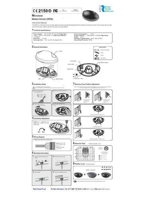
M icrowaveMotion Sensor (HR50)Instruction ManualThe HR50 is a high performance motion detection sensor specifically designed for the activation of automatic doors.For the safe and accurate use of this product, please read this instruction manual carefully.1 Technical specifications2 General Information3 Installation Guide7 Detection Area Position AdjustmentMin.Max.Power Supply : DC 12~30V, AC 12~24V Product Size :120mm ˣ 70mm ˣ 41.5mm (W ˣ L ˣ H)Microwave Module :24.125GHzHold Time : 1.2 Sec.Detecting Field : 4m ˣ 3m (W ˣ D) (Height 2.2m )Current Consumption : < 1.4WContact Capacity : 0.5A/125VAC, 1A/24VDC Max InstallHeight : 4.0mOperating Temp/Humidity : -20°C~+60°C/0~90%International Protection : IP54NONC213Sensitivity is adjustable bysetting the volume on thesensor body4< Default value : NO ><Accessories>Mounting TemplateCableScrewInstructionsCable HoleScrew HoleSensitivity volumeConnector4 Sensitivity AdjustmentDC 12~30VAC 12~24VOutput(Gray)(Yellow)2 power wires & 2 relay contact wires.5 Wiring Diagram8 Detection Field(Mounting Height : 2.2m)DefaultSensitivitySensing modulevertical angleS6 : 30°Sensing modulevertical angleS8 : 40°S6 : 6 Step(30°)Left angle rotation : 15°(Max : 30°)Front angle rotation : 0°Right angle rotation : 15°(Max : 30°)S7 : 7 Step(35°)S8 : 8 Step(40°)S11 : 11 Step(55°)Sensing Modulevertical angle30°40°Affix mounting template totransom and drill holes.Connect power cable to thesensor bodyAttach the sensor body to the wallTilt the sensing module angleUp • Down • Left • Right to change the detectionareaDo not supply power during installation.Do not disassemble or modify the device, it may cause fire or electric shockAdjust the Sensing module up and down to achieve a detection area close to or far from the door.Adjust the Sensingmodule to the right and left to achieve the desired side approach detection area.6 Mounting InformationAvoid moving objects close to thesensor13Avoid vibration2Avoid heavy rain and snow4Avoid fluorescent light sources9 Weather Cover(Sold Separately)MODEL: WCHR50The specifications of this product can be changed without prior noticeCanadaIC: 6902A-IPM165USU.S.FCC ID: UXS-IPM165FLEDSensingModuleCoverSensor BodymmFor More Information - Tel: +61 7 3205 1123 Email:***************.au Web: .au Rotech Group Pty Ltd。
QFA2050 MO、QFA2050D MO和QPA2052 MO商业通信模块的基本文档说明书

Room Humidity and Air Quality Sensors:–QFA2050/MO, QFA2050D/MO–QPA2052/MOModbus RTU (RS-485)Basic DocumentationA6V12045847_en--_a Smart Infrastructure 2020-07-23Table of Contents1About this document (3)1.1 Revision history (3)1.2 Before you start (3)2Product overview (5)2.1 Type summary (5)2.2 Product documentation (5)3Wiring (6)4Configuration (7)4.1 DIP switch to configure method selection (7)4.2 Modbus configuration parameters (7)4.3 Modbus registers (8)4.4 DIP switch configuration (9)4.5 Bus termination (11)5Maintenance (12)5.1 Disposal (12)6Appendices (13)6.1 Cyber security disclaimer (13)6.2 FCC (13)2 | 14A6V12045847_en--_aAbout this documentRevision history1A6V12045847_en--_a 3 | 141About this document1.1Revision historyEdition Date Changes Section a2020-07First version.All1.2Before you startThis document may be duplicated and distributed only with the expressed permission of Siemens Switzerland Ltd.These documents were prepared with great care.●The content of all documents is checked at regular intervals.●All necessary corrections are included in subsequent versions.●Documents are automatically amended as a consequence of modifications andcorrections to the products described.Please ensure that you have the latest document revision.If you have any questions or suggestions about this document, or if you have any criticisms or suggestions, please contact your local point of contact (POC) at the nearest branch office. Addresses for Siemens RCs are available at /sbt .MarkupsSpecial markups are indicated in the document as follows:●Numbered lists and instructions with an operation sequence 1.2.Procedures must be performed in the specified order.[➙ X]Reference to a page numberSymbol identificationsWARNINGThis is the symbol for hazard. It warns you of Risks of ply with all measures designated by this symbol to prevent injury or death.NOTICEThis symbol identifies an important notice that you should be aware of when you are using the product.Before using products from Siemens Switzerland Ltd., it is important that you carefully read the documents supplied with or ordered at the same time as the products (equipment, applications, tools, and so on).We assume that users are authorized and trained appropriately and have the technical knowledge required to use our products as intended.Additional information on products and applications is available:Copyright Quality assuranceConventions for text markingDocument use/ request to the readerAbout this document Before you start14 | 14A6V12045847_en--_a●From your Siemens branch office /sbt or at your system suppliers.●From the support team at headquarters ***********************************if no local POC is available. Siemens assumes no liability to the extent allowed under the law for any losses resulting from a failure to comply with the aforementioned points or for the improper compliance of the same.Product overview Type summary2A6V12045847_en--_a 5 | 142Product overviewThe sensors are used in ventilation and air conditioning plants.2.1Type summaryProduct numberSSN No.Measurement parameter Output signal CO 2Temperature Relative humidity QFA2050/MO S55720-S508 --40...70 °C 0…100 % r.h.Modbus RTU QFA2050D/MO S55720-S509 --40…70 °C 0…100 % r.h.Modbus RTU QPA2052/MOS55720-S5100…2000 ppm-40…70 °C0…100 % r.h.Modbus RTU2.2Product documentationProduct numberDatasheet Mounting instructions QFA2050/MO, QFA2050D/MO A6V12046135A6V12031740QPA2052/MOA6V12046144A6V12031740See the datasheets and mounting instructions for detailed information. You can download the above documents at /bt/download .Wiring36 | 14A6V12045847_en--_a3WiringG Operating voltage AC 24 V ±20 % or DC 13.5...35 V G0GND+RS485 Modbus A -RS485 Modbus B RefGND_ISOConfigurationDIP switch to configure method selection4A6V12045847_en--_a 7 | 144Configuration4.1DIP switch to configure method selectionThe sensor is a Modbus RTU (RS-485) slave device and can be configured with a Modbus master when DIP2-Position 7 is OFF (default setting).The sensor has two sets of DIP switches: DIP1 and DIP2 and can be manually configured with DIP switches when DIP2-Position 7 is ON.For details, see DIP switch configuration [➙ 9].4.2Modbus configuration parametersNameRange/numeration Default ConfigurableModbus address 1...2471Baud rate (bps)0 = Auto 1 = 96002 = 192003 = 384004 = 576005 = 768006 = 115200Transmission format (start bits-data bits-parity-stop bits)0 = 1-8-E-11 = 1-8-O-12 = 1-8-N-13 = 1-8-N-20BasicParityEven Odd NoneEven Stop bits 1 / 21Data8 bits (0…255)-Configuration Modbus registers48 | 14A6V12045847_en--_aName Range/numeration Default Identity Slave -Cable length< 600 m-NOTES :●Register 764 (Modbus address) cannot be configured as 246 via a master.Address 246 is reserved for on-event addressing.4.3Modbus registersHolding Register (16-bit)No.DescriptionRangeUnitScaling DefaultR/W1Temperature value -327…327 °C -556.6…620.6 °F°C °F 0.01-R2Temperature reliability 0 – No error1 – Bad reliability, unavailable---R3Relative humidity value 0…100 %%0.01-R 4Humidity reliability0 – No error1 – Bad reliability, unavailable---R5CO 2 value 0…2000 ppm ppm --R 6CO 2 reliability0 – No error1 – Bad reliability, unavailable---R223Temperature offset -100...100 °C -180...180 °F°C °F 0.10RW224Relative humidity offset -100...100 %%0.10RW 225CO2 offset -2000...2000 ppm ppm 1.00RW 401System unit0 – Celsius 1 – Fahrenheitothers - invalid value to be discard--RW1286SW version: Major &Minor versions ----R 1287SW version: Build version----R 764Modbus address 1…247--1RW 765Baud rate0 = Auto 1 = 9600bps 2 = 19200bps 3 = 38400bps 4 = 57600bps 5 = 76800bps 6 = 115200bps--RW766Transmission format (start bits-data bits-parity-stop bits)0 = 1-8-E-11 = 1-8-O-12 = 1-8-N-13 = 1-8-N-2--0RWNOTES:ConfigurationDIP switch configuration4A6V12045847_en--_a 9 | 14●The register number starts at 1.●The sensor rejects a command with an error notice in the event of a multiple-writing command from the master with invalid values. The register values remain unchanged.●Software version format: Major version is 1 byte, minor version is 1 byte and build version is 2 bytes, such as [2.01.33] = 0x02010021.●Supports only the holding register.4.4DIP switch configurationThe Modbus setting can be configured via DIP switches ( DIP2-position 7 must be set to ON).NOTICE●Modbus registers 764…766 are not writable via a master under DIP switches configuration.●When DIP1-position 1...8 are set to 255 and DIP2-position 7 is ON, Modbus parameters are reset to factory default settings: Only Modbus address, baud rate and transmission format are reset to factory default.The sensor has two sets of DIP switches: DIP1 and DIP2.DIP1Address configurationConfigurationDIP switch configuration410 | 14A6V12045847_en--_a2726252423222120Address12345678OFF OFF OFF OFF OFF OFF OFF OFF 0(default)OFF OFF OFF OFF OFF OFF OFF ON 1OFF OFF OFF OFF OFF OFF ON OFF 2OFF OFF OFF OFF OFF OFF ON ON 3OFF OFF OFF OFF OFF ON OFF OFF 4………………………ONONONONONONONON255NOTES:●Modbus address configuration: Valid address range 1…247, others = 0●Newly set values of register 764…766 are not activated for an invalid address;the registers retain the previous value.Baud rateParityStop bit 1)Configuration Function1234567OFF OFF OFF 0 = Auto OFF OFF ON 1 = 9600OFF ON OFF 2 = 19200OFF ON ON 3 = 38400ON OFF OFF 4 = 57600ON OFF ON 5 = 76800ON ON OFF 6 = 115200ONONONothers = AutoOFF OFF 0 = Even (default)OFF ON 1 = Odd ON OFF 2 = No parity ON ONothers = Even OFF 1 (default)ON2OFF Configurable via master ONDIP switchesNOTE:1) Parity + Stop bit only support the following combinations: 1-8-E-1, 1-8-O-1, 1-8-N-1 and 1-8-N-2. Others will be treated as 1-8-E-1.DIP2Baud rate, transmission format, configurationConfigurationBus termination 4A6V12045847_en--_a 11 | 144.5Bus terminationJumper position descriptions:●Jumper position (OFF) = disable terminating resistor (factory setting)●Jumper position (ON) = enable terminating resistorMaintenance Disposal 512 | 14A6V12045847_en--_a5Maintenance5.1DisposalAppendicesCyber security disclaimer 6A6V12045847_en--_a 13 | 146Appendices6.1Cyber security disclaimerSiemens provides a portfolio of products, solutions, systems and services that includes security functions that support the secure operation of plants, systems,machines and networks. In the field of Building Technologies, this includes building automation and control, fire safety, security management as well as physical security systems.In order to protect plants, systems, machines and networks against cyber threats, it is necessary to implement – and continuously maintain – a holistic, state-of-the-art security concept. Siemens’ portfolio only forms one element of such a concept.You are responsible for preventing unauthorized access to your plants, systems,machines and networks which should only be connected to an enterprise network or the internet if and to the extent such a connection is necessary and only when appropriate security measures (e.g. firewalls and/or network segmentation) are in place. Additionally, Siemens’ guidance on appropriate security measures should be taken into account. For additional information, please contact your Siemens sales representative or visit https:///global/en/home/company/topic-areas/future-of-manufacturing/industrial-security.html .Siemens’ portfolio undergoes continuous development to make it more secure.Siemens strongly recommends that updates are applied as soon as they are available and that the latest versions are used. Use of versions that are no longer supported, and failure to apply the latest updates may increase your exposure to cyber threats. Siemens strongly recommends to comply with security advisories on the latest security threats, patches and other related measures, published, among others, under https:///cert/en/cert-security-advisories.htm .6.2FCCThis device complies with part 15 of the FCC rules. Operation is subject to the following two conditions:1.This device may not cause harmful interference;2.This device must accept any interference received, including interference that may cause undesired operation.Changes or modifications not expressly approved by the party responsible for compliance could void the user's authority to operate the equipment.NOTE : This equipment has been tested and found to comply with the limits for a Class B digital device, pursuant to part 15 of the FCC Rules. These limits are designed to provide reasonable protection against harmful interference in a residential installation. This equipment generates, uses and can radiate radio frequency energy and, if not installed and used in accordance with the instructions,may cause harmful interference to radio communications. However, there is no guarantee that interference will not occur in a particular installation. If this equipment does cause harmful interference to radio or television reception, which can be determined by turning the equipment off and on, the user is encouraged to try to correct the interference by one or more of the following measures:●Reorient or relocate the receiving antenna.●Increase the separation between the equipment and receiver.●Connect the equipment into an outlet on a circuit different from that to which the receiver is connected.●Consult the dealer or an experienced radio/TV technician for help.CAN ICES-3 (B)/NMB-3(B)Issued bySiemens Switzerland LtdSmart InfrastructureGlobal HeadquartersTheilerstrasse 1aCH-6300 Zug+41 58 724 2424/buildingtechnologies© Siemens Switzerland Ltd, 2020Technical specifications and availability subject to change without notice.A6V12045847_en--_a。
欧艾雅(E8Y)压力传感器产品参考handbook说明书
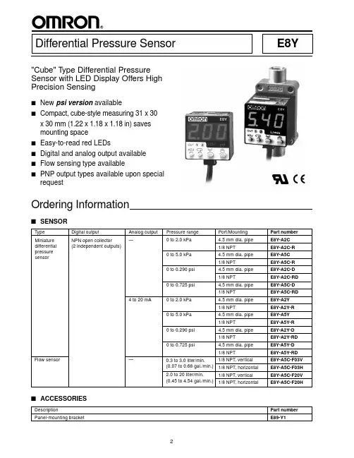
2"Cube" T ype Differential Pressure Sensor with LED Display Offers High Precision SensingsNew psi version availables Compact, cube-style measuring 31 x 30x 30 mm (1.22 x 1.18 x 1.18 in) saves mounting spacesEasy-to-read red LEDss Digital and analog output availablesFlow sensing type availables PNP output types available upon special requestOrdering InformationDifferential Pressure SensorE8Ys SENSORSpecificationss RATINGS/CHARACTERISTICSItem E8Y-A2C E8Y-A5C E8Y-A2Y E8Y-A5Y E8Y-A5C-F03V E8Y-A5Y-F20V E8Y-A2C-R E8Y-A5C-R E8Y-A2Y-R E8Y-A5Y-R E8Y-A5C-F03H E8Y-A5Y-F20HE8Y-A2C-D E8Y-A5C-D E8Y-A2Y-D E8Y-A5Y-DE8Y-A2C-RD E8Y-A5C-RD E8Y-A2Y-RD E8Y-A5Y-RDSensor type Differential pressure sensor Flow sensorPower supply voltage12 to 24 VDC ±10%, ripple (p-p) 10% max.Current consumption50 mA max.75 mA max.50 mA max.Pressure type Differential pressure Differential pressure sensingRated pressure /0 to 2.0 kPa0 to 5.0 kPa0 to 2.0 kPa0 to 5.0 kPa0.3 to 3.0 L/min. 2.0 to 20.0 L/min. volume range0 to 0.29 psi0 to 0.73 psi0 to 0.29 psi0 to 0.73 psi0.068 to 0.68 gal/min.0.45 to 4.54 gal/min. Withstand pressure /50 kPa (7.25 psi) 5 L/min (1.14 gal)40 L/min (9.08 gal) volumeApplicable fluid Non-corrosive gas and non-flammable gasAccuracy±3% FS max.Linearity±1% FS max.Responce time±0.5 sec max.(digital output)Linear output— 4 to 20 mA ±1%FS with a—permissible resistive loadof 250 ΩDigital output NPN open collector (NO/NC)Load current: 100 mA max.Applied voltage: 30 VDC max.Residual voltage: 1 V max. with a load current of 100 mA or 0.4 V max. with a load current of 16 mADisplay 3 digit red LED; the orange LED indicator is lit for two independent outputs.Display accuracy±1% FS±3% FSCircuit protection Reverse polarity connection, load short-circuitingAmbient temperature Operating: -10°C to 55°C (14°F to 131°F) with no icingStorage: -25°C to 65°C (-13°F to 149°F)Ambient humidity Operating: 25% to 85% (with no condensation)Temperature influence±3% FS max.Voltage influence±1.5% FS max.Setting resolution0.01 kPa0.001 psi0.0 1L/min.0.1 L/min. Insulation resistance100 MΩ (at 500 VDC) between current-carry parts and caseDielectic strength1,000 VAC 50/60 Hz at 1 min.Vibration resistance Endurance: 10 to 500 Hz, 1.0-mm double amplitude or 150 m/s2, 3 times each for 11 min. in X, Y and Z directions Shock resistance Endurance: 300 m/s2 (30G) 3 times each to X,Y and Z directionsDegree of protection IEC60529, IP40Pressure port NPT 1/8 female screw or 4.5 dia. pipe1/8 NPT female screwConnection method Pre-wired (standard length: 2 m)Cable Approved by ULWeight Approx. 80 g (2.8 oz)Approx. 160 g (5.6 oz)(including packing material)(including packing material)Material Pressure port: resin pipe for 4.5 dia., zinc die-cast for 1/8 NPT taper screwCase: heat-resistant PBTAccessories Mounting bracket and instruction sheet Instruction sheet34Nomenclatures E8Y PRESSURE SENSORDisplayDisplays the measured pressure and some menu settings.Shows the measuring unit. Unit currently in use is illuminated.In measurement mode, it lights when OUT 1 output is on.In setting mode, it flashes when OUT 1 is being set.In measurement mode, it lights when OUT 2 output is on.In setting mode, it flashes when OUT 2 is being set.Operation keyIn measurement mode, it adjusts the Zero Point. In setting mode, it shifts to measurement mode.Selects the current number setting or menu option.In measurement mode, pushing the DOWN key displays the ON and OFF points of OUT 1; pushing the UP key displays the ON and OFF points of OUT 2. In setting mode, the UP and DOWN keys increase or decrease the numeric value, respectively, or scroll through the menuoptions.567Application ExamplesFilterE8YE8YE8Y- -FN 2Lead FrameE8Y- -Fs DETECTION OF FILTERCLOGGINGs EXHAUST FAN ROTATION DETECTIONs DETECTION OF FLOW s AIR FLOW CONTROL(This table continues on the next page)5Functions Table - continued from previous page(2) Teaching error display:Warning if teaching is unsuccessful.(3) Short-circuit protection and display:If overcurrent flows in a connected load, the abnormal status is notified by an error display and the OUT LED,(4) Abnormal pressure or flow detection:The diplayed value flashes to indicate the abnormal status if the applied pressure or flow exceeds the rated(5) ON/OFF point input error warning:Indicates if the difference between the ON point and OFF point in the window mode exceeds the hysteresis67s OUTPUT CIRCUIT DIAGRAMs WIRINGColor Comparison output type Linear output type Brown Power supply 12 to 24 V Power supply 12 to 24 V Blue 0 V0 VBlack Comparison output 1Comparison output 1White Comparison output 2Comparison output 2Gray—Linear outputDimensionsUnit: mm (inch)s CONTROLLER OF PRESSURE SENSORE8Y-A2CE8Y-A5C E8Y-A2Y E8Y-A5Y E8Y-A2C-DE8Y-A5C-DE8Y-A2Y-D E8Y-A5Y-DDie-cast Port (Pressure Port Rc(PT) 1/8) Type E8Y-A2C-R E8Y-A5C-R E8Y-A2Y-R E8Y-A5Y-R E8Y-A2C-RDE8Y-A5C-RDE8Y-A2Y-RD E8Y-A5Y-RDOUT1(Yellow)OUT2(Y ellow)Main circuit of pressure sensorOUT1OUT2BrownLoadBlackWhiteGrayBlue100mA max.12 to 24 VLoad100 mA max.Load0 VLinear output (4 to 20 mA)Unit: mm (inch)s ACCESSORIESMounting Bracket A Mounting Bracket BProvided with E8Ys CONTROLLER OF FLOW SENSORVertical-mounting TypeE8Y-A5C-F03VE8Y-A5C-F20VHorizontal-mounting TypeE8Y-A5C-F03HE8Y-A5C-F20H(through)Two-3.7 dia.(through)Two-M3 screw8s PANEL MOUNTING BRACKETE89-Y1 Panel Mounting Bracket (sold separately)Note: Approximate panel thickness is 1.0 to 3.5 mm.6486 With Mounting 36 PanelWith Mounting 45 PanelCover GuideFrameHolder36 x 36 Panel45 x 45 Panel (DIN size)Cover GuideHolder(Panel)CoverGuideFrameHolder(Panel)9Precautionss ENVIRONMENT•Do not use this product where explosive gas, ignitable gas,or any other harmful gas may be present.•Do not use beyond rated supply voltage or under AC power supply. Explosion or fire may be caused.•Do not mix up DC pole's wiring. Explosion or fire may be caused.•This product cannot be used under corrosive gas or flammable gas.•Do not install beside high voltage line or power line.•Do not expose to water.•Do not effect the product by ultrasonic vibration.s CORRECT USE•Use within rated pressure.•Do not mix up connecting +, – sign of pressure port. The "+"sign is for plus pressure, the "–" sign for minus pressure.•Do not pull the cable more than 50 N (11.25 lbs).•Filter the gas with an appropriate air filter so that the applied gas will be free of moisture or oil.•When not using linear output and/or the ON/OFF output, cut the output lead wire and cover the tip with an insulation tube to prevent wrong connection.OMRON ELECTRONICS LLCOMRON CANADA, INC.One East Commerce Drive 885 Milner AvenueSchaumburg, IL 60173Scarborough, Ontario M1B 5V81-800-55-OMRON416-286-6465Cat. No. CEDSAX411/01Specifications subject to change without notice.Printed in the U.S.A.OMRON ON-LINEGlobal - USA - /oei Canada - /oci。
Eaton Enhanced 50系列光电传感器产品说明书
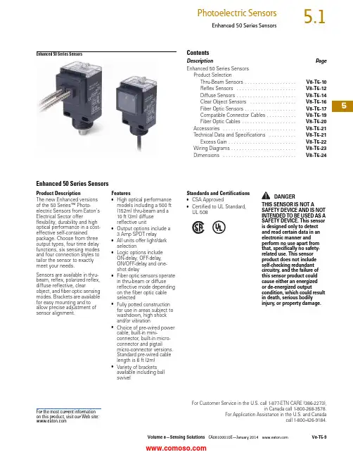
Volume 8—Sensing Solutions CA08100010E—January V8-T5-95For Customer Service in the U.S. call 1-877-ETN CARE (386-2273),in Canada call 1-800-268-3578.For Application Assistance in the U.S. and Canadacall 1-800-426-9184.Enhanced 50 Series SensorsEnhanced 50 Series SensorsContentsDescriptionPageEnhanced 50 Series Sensors Product SelectionThru-Beam Sensors . . . . . . . . . . . . . . . . . . .V8-T5-10Reflex Sensors . . . . . . . . . . . . . . . . . . . . . .V8-T5-12Diffuse Sensors . . . . . . . . . . . . . . . . . . . . . .V8-T5-14Clear Object Sensors . . . . . . . . . . . . . . . . .V8-T5-16Fiber Optic Sensors . . . . . . . . . . . . . . . . . . .V8-T5-17Compatible Connector Cables . . . . . . . . . . .V8-T5-19Fiber Optic Cables . . . . . . . . . . . . . . . . . . . .V8-T5-20Accessories . . . . . . . . . . . . . . . . . . . . . . . . . . .V8-T5-21Technical Data and Specifications . . . . . . . . . .V8-T5-21Excess Gain . . . . . . . . . . . . . . . . . . . . . . . . .V8-T5-22Wiring Diagrams . . . . . . . . . . . . . . . . . . . . . . . .V8-T5-23Dimensions . . . . . . . . . . . . . . . . . . . . . . . . . . .V8-T5-24Enhanced 50 Series SensorsProduct DescriptionThe new Enhanced versions of the 50 Series™ Photo-electric Sensors from Eaton’s Electrical Sector offerflexibility, durability and high optical performance in a cost-effective self-containedpackage. Choose from three output types, four time delay functions, six sensing modes and four connection styles to tailor the sensor to exactly meet your needs.Sensors are available in thru-beam, reflex, polarized reflex, diffuse reflective, clearobject, and fiber optic sensing modes. Brackets are available for easy mounting and to allow precise adjustment of sensor alignment.Features●High optical performance models including a 500 ft (152m) thru-beam and a 10ft (3m) diffuse reflective unit●Output options include a 3Amp SPDT relay●All units offer light/dark selection●Logic options include ON-delay, OFF -delay, ON/OFF -delay and one-shot delay●Fiber optic sensors operate in thru-beam or diffuse reflective mode depending on the fiber optic cable selected●Fully potted construction for use in areas subject to washdown, high shock and/or vibration●Choice of pre-wired power cable, built-in mini-connector, built-in micro-connector and pigtailmicro-connector versions. Standard pre-wired cable length is 6 ft (2m) ●Variety of brackets available including ball swivelStandards and Certifications●CSA Approved●Certified to UL Standard, UL 508DANGERTHIS SENSOR IS NOT ASAFETY DEVICE AND IS NOT INTENDED TO BE USED AS A SAFETY DEVICE. This sensor is designed only to detect and read certain data in an electronic manner and perform no use apart from that, specifically no safety-related use. This sensor product does not include self-checking redundant circuitry, and the failure of this sensor product could cause either an energized or de-energized outputcondition, which could result in death, serious bodily injury, or property damage.For the most current information on this product, visit our Web site:5Product Selection GuideConnection OptionsCable VersionProduct SelectionMini QD (Body)Micro or Euro (Micro)QD(Body)Micro or Euro (Micro)QD(Pigtail)Thru-Beam SensorsThru-Beam Standard Range 12NotesPage V8-T5-19.1 For a complete system, order one sensor and one detector.2 For brackets compatible with these sensors, see Accessories on Page V8-T5-21.VoltageRangeSensingRangeOptimumRangeSensingBeamThru-BeamComponent Output TypeTimeDelayConnectionType CatalogNumber 10–40 Vdc200 ft(61m)0.1 to 100 ft(0.03 to 31m)Infrared Source N/A N/A 6 ft cable1150E-6517Detector NPN/PNP 250 mA no1250E-6517yes1250E-8517Detector NPN/PNP 250 mA noDetector NPN/PNP 250 mA noyes12–240 Vdc24–240 Vac200 ft(61m)0.1 to 100 ft(0.03 to 31m)Infrared Source N/A N/A 6 ft cable1150E-6513Detector Isolated outputsolid-state relay300 mA at 240 Vac/dcno1250E-6513yes1250E-8513SPDT EM relay3A at 120 Vacno1250E-6514yes1250E-8514Detector Isolated outputsolid-state relay300 mA at 240 Vac/dcnoyesDetector Isolated outputsolid-state relay300 mA at 240 Vac/dcnoyesField of View: 2.4°V8-T5-10Volume 8—Sensing Solutions CA08100010E—January Volume 8—Sensing Solutions CA08100010E—January V8-T5-115Enhanced 50 Series SensorsThru-Beam Extended Range 12NotesPage V8-T5-19.1 For a complete system, order one sensor and one detector.2 For brackets compatible with these sensors, see Accessories on Page V8-T5-21.Voltage Range Sensing Range Optimum Range Sensing Beam Thru-Beam Component Output Type Time Delay ConnectionType Catalog Number 10–40 Vdc500 ft (152m)0.1 to 250 ft (0.03 to 77m)InfraredSource N/AN/A 6 ft cable1151E-6517DetectorNPN/PNP 250 mAno 1251E-6517DetectorNPN/PNP 250 mAno 24–240 Vac(152m)(0.03 to 77m)DetectorIsolated output solid-state relay300 mA at 240 Vac/dc no 1251E-6513yes 1251E-8513SPDT EM relay 3A at 120 Vacno 1251E-6514yes 1251E-8514DetectorIsolated output solid-state relay300 mA at 240 Vac/dc no yes DetectorIsolated output solid-state relay300 mA at 240 Vac/dc no yes DetectorIsolated output solid-state relay300 mA at 240 Vac/dc no yes Field of View: 2.4°5Reflex SensorsStandard Reflex 12NotesPage V8-T5-19.1 For a complete system, order one sensor and one retroreflector (see Tab 8, section 8.1).2 For brackets compatible with these sensors, see Accessories on Page V8-T5-21.3 Ranges based on 3 in retroreflector for reflex sensors.VoltageRangeSensingRange 3OptimumRange 3SensingBeam Output TypeTimeDelayConnectionType CatalogNumber 10–40 Vdc30 ft (9m)0.5 to 15 ft(0.2 to 4.6m)Visible red NPN/PNP 250 mA no 6 ft cable1450E-6517yes1450E-8517yes24–240 Vac(0.2 to 4.6m)solid-state relay300 mA at 240 Vac/dc yes1450E-85133A at 120 Vacyes1450E-8514Field of View: 1.0°V8-T5-12Volume 8—Sensing Solutions CA08100010E—January Volume 8—Sensing Solutions CA08100010E—January V8-T5-135Enhanced 50 Series SensorsPolarized Reflex 123NotesPage V8-T5-19.1 For a complete system, order one sensor and one retroreflector (see Tab 8, section 8.1).2 Polarized sensors may not operate with reflective tape. Test tape selection before installation.3 For brackets compatible with these sensors, see Accessories on Page V8-T5-21.4 Ranges based on 3 in retroreflector for reflex sensors.Voltage Range Sensing Range 4Optimum Range 4Sensing Beam Output Type Time Delay ConnectionType Catalog Number 10–40 Vdc16 ft (4.9m)0.5 to 8 ft (0.2 to 2.5m)Visible redNPN/PNP 250 mAno 6 ft cable1451E-6517yes 1451E-851712–240 Vdc 24–240 Vac16 ft (4.9m)0.5 to 8 ft (0.2 to 2.5m)Visible redIsolated output solid-state relay300 mA at 240 Vac/dcno 6 ft cable 1451E-6513yes 1451E-8513SPDT EM relay 3A at 120 Vacno 6 ft cable 1451E-6514yes 1451E-8514Field of View: 1.0°5Diffuse SensorsDiffuse Reflective 1NotesPage V8-T5-19.1 For brackets compatible with these sensors, see Accessories on Page V8-T5-21.2 Ranges based on 90% reflectance white card for diffuse reflective sensors.VoltageRangeSensingRange 2OptimumRange 2SensingBeam Output TypeTimeDelayConnectionType CatalogNumber 10–40 Vdc 5 ft (1.5m) 1 to 30 in(25 to 760 mm)Infrared NPN/PNP 250 mA no 6 ft cable1350E-6517yes1350E-8517yes24–240 Vac(25 to 760 mm)solid-state relay300 mA at 240 Vac/dc yes1350E-85133A at 120 Vacyes1350E-8514Field of View: 2.8°V8-T5-14Volume 8—Sensing Solutions CA08100010E—January Volume 8—Sensing Solutions CA08100010E—January V8-T5-155Enhanced 50 Series SensorsDiffuse Reflective Extended Range 1NotesPage V8-T5-19.1 For brackets compatible with these sensors, see Accessories on Page V8-T5-21.2 Ranges based on 90% reflectance white card for diffuse reflective sensors.Voltage Range Sensing Range 2Optimum Range 2Sensing Beam Output Type Time Delay ConnectionType Catalog Number 10–40 Vdc10 ft (3m)1 to 60 in(25 to 1520 mm)InfraredNPN/PNP 250 mAno 6 ft cable1351E-6517yes 1351E-851712–240 Vdc 24–240 Vac10 ft (3m)1 to 60 in(25 to 1520 mm)InfraredIsolated output solid-state relay300 mA at 240 Vac/dcno 6 ft cable 1351E-6513yes 1351E-8513SPDT EM relay 3A at 120 Vacno 6 ft cable 1351E-6514yes 1351E-8514Field of View: 2.8°5Clear Object SensorsClear Object Detector 12NotesPages V8-T5-19 and V8-T5-20.1 For a complete system, order one sensor and one retroreflector (see Tab 8, section 8.1).2 For brackets compatible with these sensors, see Accessories on Page V8-T5-21.VoltageRangeSensingRangeOptimumRangeSensingBeam Output TypeTimeDelayConnectionType CatalogNumber 10–40 Vdc45 in (1.2m) 1 to 24 in(25 to 610 mm)Visible red NPN/PNP 250 mA no 6 ft cable1452E-6517yes1452E-8517yes24–240 Vac(25 to 610 mm)solid-state relay300 mA at 240 Vac/dc yes1452E-85133A at 120 Vacyes1452E-8514Field of View: 0.68°V8-T5-16Volume 8—Sensing Solutions CA08100010E—January Volume 8—Sensing Solutions CA08100010E—January V8-T5-175Enhanced 50 Series SensorsFiber Optic SensorsFiber Optic Infrared 1NotesPages V8-T5-19 and V8-T5-20.1 For brackets compatible with these sensors, see Accessories on Page V8-T5-21.2 Field of view depends on fiber selected.3 For a complete system, order one sensor and one fiber optic cable (see Pages V8-T5-19 and V8-T5-20).4 Infrared fiber optic sensors are compatible with glass fiber optic cables (E51KE_).5 Diffuse mode—up to6 in (152 mm); thru-beam—up to 35 in (890 mm).Voltage Range Sensing RangeOptimum RangeSensing BeamOutput Type Time Delay ConnectionType Catalog Number 10–40 VdcDepends on fiber selected 5Depends on fiber selectedInfrared NPN/PNP 250 mAno 6 ft cable1550E-651712–240 Vdc 24–240 VacDepends on fiber selected 5Depends on fiber selectedInfrared Isolated outputsolid-state relay300 mA at 240 Vac/dcno 6 ft cable1550E-6513yes 3A at 120 Vacyes 1550E-8514Field of View: 234V8-T5-18Volume 8—Sensing Solutions CA08100010E—January 5Fiber Optic Visible 1NotesPage V8-T5-19.1 For brackets compatible with these sensors, see Accessories on Page V8-T5-21.2 Field of view depends on fiber selected.3 For a complete system, order one sensor and one fiber optic cable (see Page V8-T5-20).4 Visible fiber optic sensors are compatible with plastic fiber optic cables only.5 Diffuse mode—up to 3 in (76 mm); thru-beam—up to 35 in (890 mm).Voltage Range Sensing RangeOptimum RangeSensing BeamOutput Type Time Delay ConnectionType Catalog Number 10–40 VdcDepends on fiber selected 5Depends on fiber selected InfraredNPN/PNP 250 mAno 6 ft cable1551E-6517yes 1551E-851724–240 Vacselected 5selected solid-state relay300 mA at 240 Vac/dcyes 1551E-8513yes 3A at 120 Vacyes 1551E-8514Field of View: 2345Enhanced 50 Series SensorsCompatible Connector CablesStandard Cables—Micro1Standard Cables—Mini1Note1 For a full selection of connector cables, see Tab 10, section 10.1.Voltage StyleNumber of PinsGauge LengthPin Configuration/Wire Colors(Face View Female Shown)PVC Jacket Catalog Number PUR Jacket Catalog NumberIRR PUR Jacket Catalog NumberMicro-Style, Straight Female AC Micro4-pin,4-wire22 AWG6 ft (2m)CSAS4F4CY 2202 CSAS4F4RY 2202CSAS4F4IO 22025-pin,5-wire22 AWG 6 ft (2m)CSAS5A5CY2202——DC4-pin,4-wire22 AWG 6 ft (2m)CSDS4A4CY 2202 CSDS4A4RY 2202CSDS4A4IO 2202Current Rating at 600VVoltage StyleNumber of PinsGaugeLengthPin Configuration/Wire Colors(Face View Female Shown)Catalog NumberMini-Style, Straight Female 8AAC/DC4-pin,4-wire16 AWG6 ft (2m)CSMS4A4CY16025-pin, 5-wire16 AWG 6 ft (2m)CSMS5A5CY1602Micro-Style, Straight FemaleMini-Style,Straight Female5Fiber Optic CablesGlass Fiber Optic CablesGlass Fiber Optic Cables—Duplex Cables(for Diffuse Reflective Sensing)Glass Fiber Optic Cables—Single Cables(for Thru-Beam Sensing)Plastic Fiber Optic CablesPlastic Fiber Optic Cables—Pre-Assembled Duplex CablesPlastic Fiber Optic Cables—Pre-Assembled Single CablesNotes1 Larger diameter (1.5 mm) fibers provide approximately 50% longer sensing range than small diameter (1 mm).2 One cable.3 Set of two.Fiber BundleSize Ain In (mm)Stainless SteelJacketCatalog NumberPVC/MonocoilJacketCatalog NumberForward Viewing, Unthreaded0.125 (3.2)E51KE713E51KE313Right Angle Viewing, Unthreaded0.125 (3.2)E51KE733E51KE333Forward Viewing, Threaded Cable End0.125 (3.2)E51KE723E51KE323Right Angle Viewing, Threaded Cable Shaft0.125 (3.2)E51KE7A3E51KE3A3Right Angle Viewing, Threaded Cable End0.125 (3.2)E51KE7B3E51KE3B3Dimensions, see Page V8-T5-25.Sensing Tip StyleForward Viewing,UnthreadedRight Angle Viewing,UnthreadedForward Viewing,Threaded Cable EndRight Angle Viewing,Threaded Cable ShaftRight Angle Viewing,Threaded Cable EndFiber BundleSize Ain In (mm)Stainless SteelJacketCatalog NumberPVC/MonocoilJacketCatalog NumberForward Viewing, Unthreaded0.125 (3.2)E51KE813E51KE413Right Angle Viewing, Unthreaded0.125 (3.2)E51KE833E51KE433Forward Viewing, Threaded Cable End0.125 (3.2)E51KE823E51KE423Right Angle Viewing, Threaded Cable Shaft0.125 (3.2)E51KE8A3E51KE4A3Right Angle Viewing, Threaded Cable End0.125 (3.2)E51KE8B3E51KE4B3Dimensions, see Page V8-T5-25.Sensing Tip StyleForward Viewing,UnthreadedRight Angle Viewing,UnthreadedForward Viewing,Threaded Cable EndRight Angle Viewing,Threaded Cable ShaftRight Angle Viewing,Threaded Cable EndFiber Diameterin In (mm) Catalog NumberLarge Diameter, Threaded Tip0.059 (1.5)6324E-6501 12Large Diameter, Threaded Tip with Bendable Probe0.039 (1.0)6324E-6502 2Dimensions, see Page V8-T5-25.Sensing Tip StyleLarge Diameter,Threaded TipLarge Diameter,Threaded Tip withBendable ProbeFiber Diameterin In (mm) Catalog NumberLarge Diameter, Threaded Tip0.059 (1.5)6323E-6501 13Large Diameter, Threaded Tip with Bendable Probe0.039 (1.0)6323E-6502 3Dimensions, see Page V8-T5-25.Sensing Tip StyleLarge Diameter,Threaded TipLarge Diameter,Threaded Tip withBendable Probe5Enhanced 50 Series SensorsAccessoriesEnhanced 50 Series SensorsTechnical Data and SpecificationsEnhanced 50 Series SensorsDescriptionCatalog NumberMounting Bracket Right Angle—ShortProvides for full 360° rotation of sensor.Bracket slots allow for up to 1.5 in of vertical adjustment. Nickel plated6150E-6501Mounting Bracket Right Angle—T allProvides for full 360° rotation of sensor.Bracket slots allow for up to 1.5 in of vertical adjustment in each slot, and 3.5 in of overall positioning adjustment.6150E-6502Mounting Bracket Right Angle—Ball SwivelProvides for full 360° rotation of sensor. Ball swivel allows for ±30° sensor angle.6150E-6503RetroreflectorsRetroreflectors and retroreflective tape, see Tab 8, section 8.1—Connector CablesFor use with connector version sensors, see Tab 10, section 10.1—Dimensions , see Page V8-T5-25.Description AC/DCEM Relay ModelSpecification AC/DCSolid-state Relay Model Specification DC OnlyStandard Range Model Specification DC OnlyExtended Range Model Specification Input voltage 12–240 Vdc; 24–240 Vac 12–240 Vdc; 24–240 Vac 10–40 Vdc 10–40 Vdc Light/dark operation Switch selectableSwitch selectableSwitch selectableSwitch selectableOperating temperature –13° to 131°F (–25° to 55°C)–13° to 131°F (–25° to 55°C)–13° to 131°F (–25° to 55°C)–13° to 131°F (–25° to 55°C)Humidity 95% Relative humidity, non-condensing 95% Relative humidity, non-condensing 95% Relative humidity, non-condensing 95% Relative humidity, non-condensing Case material Fiberglass reinforced plastic Fiberglass reinforced plastic Fiberglass reinforced plastic Fiberglass reinforced plastic Lens material AcrylicAcrylicAcrylicAcrylicVibration IEC 60947-5-2 part 7.4.2IEC 60947-5-2 part 7.4.2IEC 60947-5-2 part 7.4.2IEC 60947-5-2 part 7.4.2Shock IEC 60947-5-2 part 7.4.1IEC 60947-5-2 part 7.4.1IEC 60947-5-2 part 7.4.1IEC 60947-5-2 part 7.4.1ProtectionOutput short circuit and overcurrent protection Reverse polarity protection Output short circuit and overcurrent protection Reverse polarity protection Output short circuit and overcurrent protection Reverse polarity protection Output short circuit and overcurrent protection Reverse polarity protection Enclosure ratings IP67, IP69KIP67, IP69K IP67, IP69K IP67, IP69K Output load 3A at 120 Vac; 3A at 240 Vac 3A at 28 Vac 300 mA at 240 Vac/dc 250 mA at 40 Vdc 250 mA at 40 Vdc Response time 15 ms 2 ms 2 ms 2 ms Timer timing response 0–15 sec.0–15 sec.0–15 sec.0–15 sec.No load current <30 mA <30 mA <30 mA <30 mA Leakage current (max.)—1 mA at 240 Vac<10 μA<10 μAIndicator LEDs Green: output; yellow: power; red: alignmentGreen: output; yellow: power; red: alignment Green: output; yellow: power; red: alignment Green: output; yellow: power; red: alignment Emitter LEDDiffuse, infrared fiber optic, thru-beam modelsInfrared 880 mm Infrared 880 mm Infrared 880 mm Infrared 880 mm Reflex, polarized reflex, clear object, visible fiber optic unitsVisible red 660 mm Visible red 660 mmVisible red 660 mmVisible red 660 mmMounting Bracket Right Angle—ShortMounting Bracket Right Angle—TallMounting Bracket Right Angle—Ball Swivel5Excess GainThru-BeamThru-beam1. 1151E/1251E2. 1150E/1250EDiffuse ReflectiveDiffuse reflective90% reflectance white card1. 1351E2. 1350EReflexReflex3 in retroreflector1. 1450E2. 1451EClear Object DetectorClear object detector3 in retroreflector1. 1452EFiber Optic DiffuseFiber optic diffuse0.125 in dia. glass fiber0.040 in dia. plastic fiber1. 1550E2. 1551EFiber Optic Thru-BeamFiber optic thru-beam0.125 in dia. glass fiber0.040 in dia. plastic fiber1. 1550E2. 1551E5Enhanced 50 Series SensorsWiring DiagramsPin numbers are for reference, rely on pin location when wiring. Enhanced 50 Series SensorsNotes1Connecting the test input to 0 Vdc allows you to switch the light source off for troubleshooting while leaving the sensor under power. 2Over current protection is to be provided in the field. Conductor size for 20 AWG: 5 amp; 22 AWG: 3 amp; 24 AWG: 2 amp.3Connect load to appropriate output for either sinking or sourcing operation.Operating VoltageCable ModelMini-Connector Model (Face View Male Shown)Micro-Connector Model (Face View Male Shown)Thru-Beam Source 10–40 VdcAll Others 10–40 VdcThru-Beam Source 12–240 Vdc or 24–240 Vac solid-state relay 2All Others with Isolated AC/DC Output 12–240 Vdc or 24–240 Vac solid-state relay 2Thru-Beam Source 12–240 Vdc or 24–240 Vac SPDT EM relay 2All Others12–240 Vdc or 24–240 Vac SPDT EM relay235DimensionsApproximate Dimensions in Inches (mm)Enhanced 50 Series SensorsCable and Pigtail Connector VersionsClear Object VersionsMini-Connector VersionsAC/DC Micro or Euro (Micro) Connector VersionsTop ViewsWith Timing Without Timing5Enhanced 50 Series SensorsApproximate Dimensions in Inches (mm)Glass Fiber Optic Cables—Duplex Cables Stainless Steel Jacket shown for all.Collar Mounting EndForward Viewing, UnthreadedRight Angle Viewing, UnthreadedForward Viewing, Threaded Cable EndRight Angle Viewing, Threaded Cable ShaftRight Angle Viewing, Threaded Cable EndGlass Fiber Optic Cables—Single Cables Stainless Steel Jacket shown for all.Collar Mounting EndForward Viewing, UnthreadedRight Angle Viewing, UnthreadedForward Viewing, Threaded Cable EndRight Angle Viewing, Threaded Cable ShaftRight Angle Viewing, Threaded Cable End5Approximate Dimensions in Inches (mm)Plastic Fiber Optic Cables—Pre-Assembled Duplex CablesLarge Diameter, Threaded TipLarge Diameter, Threaded Tip with Bendable ProbePlastic Fiber Optic Cables—Pre-Assembled Single CablesLarge Diameter, Threaded TipLarge Diameter, Threaded Tip with Bendable ProbeAccessoriesMounting Bracket Right Angle—ShortMounting Bracket Right Angle—T allMounting Bracket Right Angle—Ball Swivel。
美国穆格型号
美国MOOG电液伺服阀穆格电液伺服阀 MOOG伺服阀穆格伺服阀穆格MOOG三级伺服阀MOOG直动式伺服阀D634-319C D634-399C D634-1003 D634-1005 D634-1007 D634-1008 D634-514A D634-557 D634-394CD634-1009 D634-1010 D634-1011 D634-1012 D634-1013 D634-1014 D634-1015 D634-1016 D634-1018D634-1019 D634-1023 D634-1024 D634-1025 D634-1026 D634-1027 D634-1028 D634-1029 D634-1031D634-1032 D634-1033 D634-1034 D634-1035 D634-1036 D634-1037 D634-1040 D634-1041 D634-1042D634-1043 D634-1045 D634-1046 D634-1047 D634-1049 D634-1050 D634-1051 D634-1052 D634-1053D634-1054 D634-1055 D634-1056 D634-1057 D634-1058 D634-1059 D634-1060 D634-3001 D634-301CD634-305C D634-307C D634-308C D634-317C D634-318C D634-322C D634-324C D634-326C D634-384CD634-327C D634-330C D634-331C D634-335C D634-341C D634-345C D634-346C D634-358C D634-361CD634-362C D634-368C D634-371C D634-372C D634-373C D634-374C D634-381C D634-383C D633Z7397D634-385C D634-386C D634-387C D634-388C D634-389C D634-390C D634-391C D634-392C D633Z7383D634-396C D634-397C D634-398C D634-400C D634-402C D634-403C D634-404C D634-405C D634-1001D634-406 D634-501A D634-502A D634-503 D634-504 D634-508 D634-511 D634-512A D634-513 D634-515 D634-516A D634-517 D634-518A D634-520A D634-521 D634-524A D634-525AD634-526D634-527A D634-528A D634-529A D634-530A D634-531 D634-532 D634-533 D634-534D634-536AD634-537A D634-538A D634-539 D634-540A D634-541 D634-542A D634-543A D634-544AD634-545D634-546A D634-547 D634-548 D634-550 D634-551 D634-552 D634-553A D634-554A D634-555 D634-558 D634-559 D634-560 D634K2000C D634K2001C D634K2002C D634K2003C D634K2004C D634K2005C D634K2006C D634K2007C D634K2008C D634K2009C D634K2010C D634K2011CD634K2012C D634K2013CD634K2014C D634K2015C D634K2016C D634K2017C D634K2018C D634K2019C D634K2020D634Z1020D634Z1021 D634Z1022 D634Z1038 D634Z1044 D634Z314C D634Z351C D634Z359CY D634Z360CD634Z360CYD634Z380C D634Z395C D634Z505A D634Z509 D634Z510 D634Z549A D633E703 D633E704D633E713AD633E714A D633E7365 D633E7366 D633E7411 D633K2000B D633K2001B D633K2002BD633K2003BD633K2005B D633K2006B D633K2007B D633K2008B D633K2009B D633K2010B D633K2011BD633K2012BD633K2013B D633K2014B D633K2015B D633K2017B D633K2018B D633K2019B D633K2020BD633K2021BD633K2022B D633K2023B D633K2024B D633K2025B D633K2026B D633K2027B D633K2028BD633K2029BD633K2030B D633K2031B D633K2032B D633K2033B D633K2034B D633K2035B D633K2036BD633K2037BD633K2038B D633K2039B D633K2040B D633K2041B D633K2042B D633K2043B D633K2044BD633K2045BD633K2046B D633K2047B D633K2048B D633K2049 D633K2050 D633K2051 D633Z303B D633Z305B D633Z313BD633Z317B D633Z338B D633Z348B D633Z371B D633Z379B D633Z480B D633Z506B D633Z528B D633Z529BD633Z532B D633Z539B D633Z557B D633Z570B D633Z585B D633Z586B D633Z587B D633Z588B D633Z589BD633Z590B D633Z7309 D633Z7324 D633Z7337 D633Z7352 D633Z7353 D633Z7361 B67728-001 B67728-002B67728-003 A03665-060美国Moog伺服阀说明:美国Moog伺服阀MOOG穆格伺服阀D633,D634系列,G761-3005,G761-3004,G761-3003,G761-3002,G761-3001,J761,J072,J869,G631 G761系列伺服阀 D791三级伺服阀 D661电反馈式伺服 72系列机械反馈伺服 D633/D634直动式伺服阀功率级阀型号/先导级 MOOG机能代号 D661-4651/ C41156-421 G35JOAA6VSX2HA D661-4652/ C4 1156-421 G15JOAA6VSX2HA D661-4636/C41156-421 G60KOAA5VSX2HA D661-4469C/C41156-421 G75KOAA6VS X2HA D661-4697C/C41156-421 G15JOAA5VSX2HA D661-4033/ C41156-421 P80HAAF6VSX2-A D661-4059/C41 156-411 P80HAAF6VSX2-B D661-4444C/C41156-421 G60JOAA6VSX2HA D661-4443C/C41156-421 G45J0AA6VS X2HA D661-4506C/C41156-421 G23J0AA6VSX2HA D661-4539C/C41156-421 G35JOAA5VSX2HA MOOG型号/先导级 MOOG机能代号 D662Z4311K/D630-072A P01JXMF6VSX2-A D662-4010/D061-8411 D02HABF6VSX2-A D662Z 4336K/D630-272D P01JXMF6VSX2-A MOOG型号/先导级 MOOG机能代号 D663Z4307K/D630Z067A P02JONF6VS X2-A D663-4007/D061-8412 L03HABD6VSX2-A MOOG型号/先导级 MOOG机能代号 D663Z4307K/D630Z067A P 02JONF6VSX2-A D663-4007/D061-8412 L03HABD6VSX2-A D634-341C R40K02M0NSS2 D634-319C R40KO2M0NS P2 D633-333B R16KO1F0NSS MOOG型号/先导级 MOOG机能代号 D791-5009/D761-2612 S16J0QA6VSB0-P D7 91-4025/ S25J0PA6VSX2-A D791-4001/待查 S25J0QB6VSX2-B D791-4002/D761-2617 S25J0QB5VSX2-B D791-4028/D761-2619 S25J0QB6VSX2-B D791-4046/D761-2619 S25J0QA6VSX2-B MOOG型号 MOOG机能代号 07 2-559A S15F0FA4VBL, 072-558A S22FOFA4VBL《新型号:072-1203-10》。
NOVOHALL 旋转传感器 无触摸 RFE-3200 电压 移动应用数据参考表说明书
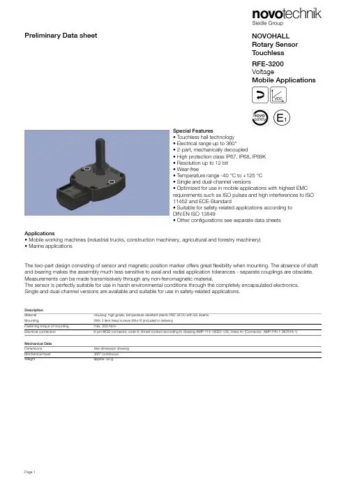
NOVOHALL Rotary Sensor TouchlessRFE-3200VoltageMobile ApplicationsPreliminary Data sheetSpecial Features• Touchless hall technology • Electrical range up to 360°• 2-part, mechanically decoupled• High protection class IP67, IP68, IP69K • Resolution up to 12 bit • Wear-free• Temperature range -40 °C to +125 °C • Single and dual-channel versions• Optimized for use in mobile applications with highest EMC requirements such as ISO pulses and high interferences to ISO 11452 and ECE-Standard• Suitable for safety-related applications according to DIN EN ISO 13849• Other configurations see separate data sheetsApplications• Mobile working machines (industrial trucks, construction machinery, agricultural and forestry machinery)• Marine applicationsThe two-part design consisting of sensor and magnetic position marker offers great flexibility when mounting. The absence of shaft and bearing makes the assembly much less sensitive to axial and radial application tolerances - separate couplings are obsolete.Measurements can be made transmissively through any non-ferromagnetic material.The sensor is perfectly suitable for use in harsh environmental conditions through the completely encapsulated electronics.Single and dual-channel versions are available and suitable for use in safety-related applications.Description Material Housing: high grade, temperature resistant plastic PBT GF30 with SS inserts MountingWith 2 lens head screws M4x18 (included in delivery)Fastening torque of mounting max. 200 NcmElectrical connection 6-pin MQS-connector, code A, tinned contact according to drawing AMP-114-18063-126, Index A1 (Connector: AMP P/N 1-967616-1)Mechanical Data Dimensions See dimension drawing Mechanical travel 360° continuous Weightapprox. 50 gSpecificationsAccessories included in delivery• 2x Lens head screws M4x18CAD data seewww.novotechnik.de/en/download/cad-data/When the marking of theposition marker pointstowards the connector,the sensor is near theelectrical center position.Technical DataType RFE-32_ _-_ _ _-3_ _-521VoltageOutput signal0.25 ... 4.75 V0.5 ... 4.5 VLoad≥ 10 kΩNumber of channels 1 / 2Diagnosis activated (in case of error, output signal is outside of the plausible signal range)Update rate typ. 3.4 kHzMeasuring range0 ... 30° up to 0 ... 360° in 10°-stepsIndependent linearity≤ ±0.5 %FSResolution12 bitsRepeatability typ. ≤ ±0.1°Hysteresis typ. < ±0.1°Only easuring range 360°: typ. < 0.25° (lower hysteresis on request)Temperature error Measuring range 30 ... 170°: typ. ±1.0 %FS, Measuring range ≥ 180°: typ. ±0.5 %FSSupply voltage Ub12/24 VDC (8 ... 34 VDC)Current consumption w/o load typ. 12 mA per channelOvervoltage protection60 VDC (10 min.)Polarity protection yes (supply lines and outputs)Short circuit protection yes (vs. GND and supply voltage)Insulation resistance (500 VDC)≥ 10 MΩEnvironmental DataMax. operational speed Mechanically unlimitedVibration IEC 60068-2-620 g, 5 ... 2000 Hz, Amax = 0.75 mmShock IEC 60068-2-2750 g, 6 msProtection class ISO 20653IP67 / IP68 / IP69KOperating temperature-40 ... +125°C** The max. operating temperature depends on supply voltage Ub (see temp.diagram)Life Mechanically unlimitedFunctional safety Suitable for safety-related applications according to ISO 13849 after customer validation.Further safety data ( DCavg...) and support for functional safety are available on request.MTTF (IEC 60050)447 years (per channel)MTTFd (EN ISO 13849-1 parts count894 years (per channel)method, w/o load)MTTFd-certificate https://www.novotechnik.de/en/downloads/certificates/mttfd-certificates/Traceability Serial number on type labeling: production batch of the sensor assembly and relevant sensor componentsEMC CompatibilityISO 10605 ESD (Handling/Component)8 kV / 15 kVISO 11452-2 Radiated HF-fields100 V/mISO 11452-5 Radiated HF-Fields, stripline200 V/mCISPR 25 Radiated emission Level 5ISO 7637-2 Transient Emissions Level 3ISO 7637-2 Pulses on supply lines(1, 2a, 2b, 3a, 3b, 4, 5) Level 4ISO 7637-3 Pulses on output lines Level 4EN 13309 Construction machineryEmission/Immunity E1acc. to ECE-R10ISO 13766-1/-2 Construction machinery On requestTechnical DataOutputCharacteristics Temperature DiagramOutput characteristic Output characteristicOutput characteristic Output characteristicOutput characteristic Output characteristicZ-RFC-P23Position marker for fixation with threaded pin M4 (included in delivery)Caution: For orientation of the output characteristic please follow the user manual of the position marker!Material PA6-GF± 3 mmMax. permittedradial offsetP/N Pack. unit [pcs] 400056074140005608525Z-RFC-P43Position marker for fixation with threaded pin M4 (included in delivery)Caution: For orientation of the output characteristic please follow the user manual of the position marker!Material PA6-GF± 3 mmMax. permittedradial offsetP/N Pack. unit [pcs] 400105041140010504225Z-RFC-P30Position marker for frontal fixation with 2 cylinder screws M3x8 (included in delivery)Material PBT-GFMax. permitted± 1.5 mmradial offsetP/N Pack. unit [pcs] 400056086140005608725Z-RFC-P31Position marker for frontal fixation with 2 cylinder screws M3x8 (included in delivery)Material PBT-GF± 3 mmMax. permittedradial offsetP/N Pack. unit [pcs] 400056088140005608925Z-RFC-P22Position marker for frontal fixation with 2 cylinder head screws M4x20 (with microencapsulation, included in delivery).Attention: Closed side of position marker faces the active side of sensor.Material Aluminium, anodized± 4 mmMax. permittedradial offsetOperating temp.-40 ... +125°CP/N Pack. unit [pcs] 400106735140010673625Z-RFC-P18Screw position marker M10 x 25 mm, similar DIN 933, magnet pottedMaterial Aluminium, anodizedMax. permitted± 3 mmradial offsetP/N Pack. unit [pcs] 400104756140010475725Z-RFC-P19Screw position marker M8 x 25 mm, similar DIN 933/ISO 4017, magnet pottedMaterial Aluminium, anodized± 1.5 mmMax. permittedradial offsetP/N Pack. unit [pcs] 400104754140010475525Z-RFC-P20Screw position marker M10 x 25 mm, similar DIN 933Material Aluminium, anodizedMax. permitted± 3 mmradial offsetP/N Pack. unit [pcs] 400104758140010475925Z-RFC-P03Magnet for direct application onto customer’s shaft (see user manual).We recommend mounting on non-magnetizable materials, otherwise the specified working distances will vary (e.g. reduction of approx. 20% with axial mounting on a magnetizable shaft).± 1.5 mmMax. permittedradial offsetP/N Pack. unit [pcs] 400005658140005608150Z-RFC-P04Magnet for direct application onto customer’s shaft (see user manual).We recommend mounting on non-magnetizable materials, otherwise the specified working distances will vary (e.g. reduction of approx. 20% with axial mounting on a magnetizable shaft).± 3 mmMax. permittedradial offsetP/N Pack. unit [pcs] 400005659140005608250Working Distances Position Markers [mm] - Single-channel VersionsZ-RFC-P03Z-RFC-P04Z-RFC-P18Z-RFC-P19Z-RFC-P20Z-RFC-P22Z-RFC-P23Z-RFC-P30Z-RFC-P31Z-RFC-P43 0.4 ... 1.9 2 ... 4.70 ... 40 ... 1.8 2 ... 4.7 4.1 ... 8.9 2 ... 4.70.4 ... 1.9 2 ... 4.70 ... 2.4Working Distances Position Markers [mm] - Redundant VersionsZ-RFC-P03Z-RFC-P04Z-RFC-P18Z-RFC-P19Z-RFC-P20Z-RFC-P22Z-RFC-P23Z-RFC-P30Z-RFC-P31Z-RFC-P43 0... 1.5 1.6 ... 4.20 ... 3.50 ... 1.3 1.6 ... 4.2 3.6 ... 8.4 1.6 ... 4.20 ... 1.5 1.6 ... 4.20 (2)Lateral Magnet OffsetLateral magnet offset willcause additional linearity error.The angle error, which iscaused by radial displacementof sensor and position markerdepends on the used positionmarker or magnet.Additional Linearity Error at Radial Displacement - Single-channel VersionsZ-RFC-P02 / P04 / P08Z-RFC-P20 / P23 / P31Z-RFC-P41 / P43 / P47Z-RFC-P03 / P30Z-RFC-P18Z-RFC-P19Z-RFC-P220.5 mm: ±0.4°1.0 mm: ±1.1°2.0 mm: ±3.5°0.5 mm: ±0.4°1.0 mm: ±1.1°2.0 mm: ±3.5°0.5 mm: ±1.4°1.0 mm: ±3.7°2.0 mm: -0.5 mm: ±0.7°1.0 mm: ±1.3°2.0 mm: ±3.3°0.5 mm: ±1.3°1.0 mm: ±2.6°2.0 mm: -1.0 mm: ±0.8°2.0 mm: ±1.8°4.0 mm: ±5.4°Additional Linearity Error at Radial Displacement - Redundant VersionsZ-RFC-P02 / P04 / P08Z-RFC-P20 / P23 / P31Z-RFC-P41 / P43 / P47Z-RFC-P03 / P30Z-RFC-P18Z-RFC-P19Z-RFC-P220.5 mm: ±0.7°1.0 mm: ±1.8°2.0 mm: ±5,2°0.5 mm: ±0.7°1.0 mm: ±1.8°2.0 mm: ±5.2°0.5 mm: ±2.5°1.0 mm: ±6.4°2.0 mm: -0.5 mm: ±1.1°1.0 mm: ±2°2.0 mm: ±4.6°0.5 mm: ±2.3°1.0 mm: ±4.5°2.0 mm: -1.0 mm: ±1.1°2.0 mm: ±2.4°4.0 mm: ±6.7°Connector System MQSMQS Micro Quadlok SystemConnector kit including• 1 plug socket (female), AMP P/N 1-967616-1• 6 tinned contacts for cable cross-section area 0.3 ... 0.5 mm² (AWG 22), AMP-P/N 963727-1• 6 single conductor sealings AMP P/N 967067-2P/N Type400005666EEM-33-34Novotechnik U.S., Inc.155 Northboro RoadSouthborough, MA 01772Phone 508 485 2244Fax 508 485 2430********************© Mar 25, 2021The specifications contained in our datasheets are intended solely for informational purposes. The documented specification values are based on ideal operational and environmental conditions and can vary significantly depending on the actual customer application. Using our products at or close to one or more of the specified performance ranges can lead to limitations regarding other performance parameters. It is therefore necessary that the end user verifies relevant performance parameters in the intended application. We reserve the right to change product specifications without notice.。
ESTIC Z50_中文样本
I/O 自由分配功能
对于 Control I/O、Extend I/O、Remote I/O(选配)的 各输入输出可以自由地分配 I/O 地址。 另外,PLC 连接或 Fieldbus 连接也可以自由分配。
通过 USB 可以直接通信
配备了通过 USB 和电脑直接通信的接口(PC-USB),即使没有
制器单元,可以进行最大 4 个紧固程序的并列 动作,多个的紧固装置通过 1 台 MU50 就可以
MU40
控制。
(左侧)
2台 必须
AU40 AU40 AU40 AU40
(右侧)
MU40
拧紧机综合管理单元(最大 31 局) 最大 4 个工作站同時多轴控制
Z50
工作组 A
AU50 AU50 AU50 AU50
工具单元参数表和控制器单元的组合
工具单元型号 ENRZ-TU0R5R-S ENRZ-TU001R-※ ENRZ-TU003R-※ ENRZ-TU004R-S ENRZ-TU008R-※ ENRZ-TU013R-※ ENRZ-TU020R-※ ENRZ-TU040R-※ ENRZ-TU060R-S ENRZ-TU080R-S
ENRZ-TU003R-O 349 28 ‒ 3 8 15 φ22g7 8 φ12h7
ENRZ-TU004R-S 302.5 35 ‒ 5 10 20 φ40g7 8 φ16h7
ENRZ-TU008R-S 329 35 ‒ 5 14 20 φ40g7 8 φ16h7
ENRZ-TU008R-O 399 35 ‒ 5 10 20 φ28g7 8 φ16h7
最高转速(rpm) 2814 1224 468 1464 714 500 291 148 113 83
英飞凌 FP50R12N2T7P EconoPIM 2 模块 数据表
EconoPIM ™2 模块 采用第七代沟槽栅/场终止IGBT7和第七代发射极控制二极管 带有温度检测NTC 和预涂导热介质特性•电气特性-V CES = 1200 V-I C nom = 50 A / I CRM = 100 A -沟槽栅IGBT7-低 V CEsat-过载操作达175°C•机械特性-高功率循环和温度循环能力-集成NTC 温度传感器-铜基板-低热阻的三氧化二铝 Al 2O 3 衬底-预涂导热介质-焊接技术可选应用•辅助逆变器•电机传动•伺服驱动器产品认证•根据 IEC 60747、60749 和 60068标准的相关测试,符合工业应用的要求。
描述FP50R12N2T7PEconoPIM ™2 模块内容描述 . . . . . . . . . . . . . . . . . . . . . . . . . . . . . . . . . . . . . . . . . . . . . . . . . . . . . . . . . . . . . . . . . . . . . . . . . . . . . . . . . . . . . . . . .1特性 . . . . . . . . . . . . . . . . . . . . . . . . . . . . . . . . . . . . . . . . . . . . . . . . . . . . . . . . . . . . . . . . . . . . . . . . . . . . . . . . . . . . . . . . .1可选应用 . . . . . . . . . . . . . . . . . . . . . . . . . . . . . . . . . . . . . . . . . . . . . . . . . . . . . . . . . . . . . . . . . . . . . . . . . . . . . . . . . . . .1产品认证 . . . . . . . . . . . . . . . . . . . . . . . . . . . . . . . . . . . . . . . . . . . . . . . . . . . . . . . . . . . . . . . . . . . . . . . . . . . . . . . . . . . .1内容 . . . . . . . . . . . . . . . . . . . . . . . . . . . . . . . . . . . . . . . . . . . . . . . . . . . . . . . . . . . . . . . . . . . . . . . . . . . . . . . . . . . . . . . . .2 1封装 . . . . . . . . . . . . . . . . . . . . . . . . . . . . . . . . . . . . . . . . . . . . . . . . . . . . . . . . . . . . . . . . . . . . . . . . . . . . . . . . . . . . . . . . .3 2IGBT, 逆变器 . . . . . . . . . . . . . . . . . . . . . . . . . . . . . . . . . . . . . . . . . . . . . . . . . . . . . . . . . . . . . . . . . . . . . . . . . . . . . . . . .3 3二极管,逆变器 . . . . . . . . . . . . . . . . . . . . . . . . . . . . . . . . . . . . . . . . . . . . . . . . . . . . . . . . . . . . . . . . . . . . . . . . . . . . . . .5 4二极管,整流器 . . . . . . . . . . . . . . . . . . . . . . . . . . . . . . . . . . . . . . . . . . . . . . . . . . . . . . . . . . . . . . . . . . . . . . . . . . . . . . .6 5IGBT, 斩波器 . . . . . . . . . . . . . . . . . . . . . . . . . . . . . . . . . . . . . . . . . . . . . . . . . . . . . . . . . . . . . . . . . . . . . . . . . . . . . . . . .7 6Diode-斩波器 . . . . . . . . . . . . . . . . . . . . . . . . . . . . . . . . . . . . . . . . . . . . . . . . . . . . . . . . . . . . . . . . . . . . . . . . . . . . . . . .8 7负温度系数热敏电阻 . . . . . . . . . . . . . . . . . . . . . . . . . . . . . . . . . . . . . . . . . . . . . . . . . . . . . . . . . . . . . . . . . . . . . . . . .9 8特征参数图表 . . . . . . . . . . . . . . . . . . . . . . . . . . . . . . . . . . . . . . . . . . . . . . . . . . . . . . . . . . . . . . . . . . . . . . . . . . . . . . .10 9电路拓扑图 . . . . . . . . . . . . . . . . . . . . . . . . . . . . . . . . . . . . . . . . . . . . . . . . . . . . . . . . . . . . . . . . . . . . . . . . . . . . . . . . .16 10封装尺寸 . . . . . . . . . . . . . . . . . . . . . . . . . . . . . . . . . . . . . . . . . . . . . . . . . . . . . . . . . . . . . . . . . . . . . . . . . . . . . . . . . . .16 11模块标签代码 . . . . . . . . . . . . . . . . . . . . . . . . . . . . . . . . . . . . . . . . . . . . . . . . . . . . . . . . . . . . . . . . . . . . . . . . . . . . . . .17修订历史 . . . . . . . . . . . . . . . . . . . . . . . . . . . . . . . . . . . . . . . . . . . . . . . . . . . . . . . . . . . . . . . . . . . . . . . . . . . . . . . . . . .18免责声明 . . . . . . . . . . . . . . . . . . . . . . . . . . . . . . . . . . . . . . . . . . . . . . . . . . . . . . . . . . . . . . . . . . . . . . . . . . . . . . . . . . .191封装表 1绝缘参数特征参数代号标注或测试条件数值单位绝缘测试电压V ISOL RMS, f = 50 Hz, t = 1 min 2.5kV 模块基板材料Cu内部绝缘基本绝缘 (class 1, IEC 61140)Al2O3爬电距离d Creep端子至散热器10.0mm 电气间隙d Clear端子至散热器7.5mm 相对电痕指数CTI>200相对温度指数 (电)RTI封装140°C 表 2特征值特征参数代号标注或测试条件数值单位最小值典型值最大值杂散电感,模块L sCE35nH 模块引线电阻,端子-芯片R AA'+CC'T H=25°C, 每个开关 5.5mΩ模块引线电阻,端子-芯片R CC'+EE'T H=25°C, 每个开关 4.8mΩ储存温度T stg-40125°C 最高基板工作温度T BPmax150°CM5, 螺丝36Nm 模块安装的安装扭距M根据相应的应用手册进行安装重量G180g注:The current under continuous operation is limited to 50 A rms per connector pin.Storage and shipment of modules with TIM => see AN2012-072IGBT, 逆变器表 3最大标定值特征参数代号标注或测试条件数值单位集电极-发射极电压V CES T vj = 25 °C1200V 连续集电极直流电流I CDC T vj max = 175 °C T H = 90 °C50A 集电极重复峰值电流I CRM t P = 1 ms100A 栅极-发射极峰值电压V GES±20V表 4特征值特征参数代号标注或测试条件数值单位最小值典型值最大值集电极-发射极饱和电压V CE sat I C = 50 A, V GE = 15 V T vj = 25 °C 1.50 1.80VT vj = 125 °C 1.64T vj = 175 °C 1.72栅极阈值电压V GEth I C = 2 mA, V CE = V GE, T vj = 25 °C 5.15 5.80 6.45V 栅极电荷Q G V GE = ±15 V, V CE = 600 V0.92µC 内部栅极电阻R Gint T vj = 25 °C0Ω输入电容C ies f = 100 kHz, T vj = 25 °C, V CE = 25 V, V GE = 0 V11.1nF 反向传输电容C res f = 100 kHz, T vj = 25 °C, V CE = 25 V, V GE = 0 V0.039nF 集电极-发射极截止电流I CES V CE = 1200 V, V GE = 0 V T vj = 25 °C0.01mA 栅极-发射极漏电流I GES V CE = 0 V, V GE = 20 V, T vj = 25 °C100nA开通延迟时间(感性负载)t don I C = 50 A, V CE = 600 V,V GE = ±15 V, R Gon = 7.5 ΩT vj = 25 °C0.059µs T vj = 125 °C0.061T vj = 175 °C0.062上升时间(感性负载)t r I C = 50 A, V CE = 600 V,V GE = ±15 V, R Gon = 7.5 ΩT vj = 25 °C0.043µs T vj = 125 °C0.047T vj = 175 °C0.049关断延迟时间(感性负载)t doff I C = 50 A, V CE = 600 V,V GE = ±15 V, R Goff = 7.5 ΩT vj = 25 °C0.290µs T vj = 125 °C0.380T vj = 175 °C0.420下降时间(感性负载)t f I C = 50 A, V CE = 600 V,V GE = ±15 V, R Goff = 7.5 ΩT vj = 25 °C0.110µs T vj = 125 °C0.200T vj = 175 °C0.270开通损耗能量 (每脉冲)E on I C = 50 A, V CE = 600 V,Lσ = 35 nH, V GE = ±15 V,R Gon = 7.5 Ω, di/dt = 900A/µs (T vj = 175 °C)T vj = 25 °C 5.07mJ T vj = 125 °C 6.76T vj = 175 °C7.72关断损耗能量 (每脉冲)E off I C = 50 A, V CE = 600 V,Lσ = 35 nH, V GE = ±15 V,R Goff = 7.5 Ω, dv/dt =2900 V/µs (T vj = 175 °C)T vj = 25 °C 3.37mJ T vj = 125 °C 5.31T vj = 175 °C 6.58(待续)表 4(续) 特征值特征参数代号标注或测试条件数值单位最小值典型值最大值短路数据I SC V GE≤ 15 V, V CC = 800 V,V CEmax=V CES-L sCE*di/dt t P≤ 8 µs,T vj=150 °C190At P≤ 7 µs,T vj=175 °C180结-散热器热阻R thJH每个 IGBT, Valid with IFX pre-appliedThermal Interface Material0.777K/W 允许开关的温度范围T vj op-40175°C注:T vj op > 150°C is allowed for operation at overload conditions. For detailed specifications, please refer to AN 2018-14.3二极管,逆变器表 5最大标定值特征参数代号标注或测试条件数值单位反向重复峰值电压V RRM T vj = 25 °C1200V 连续正向直流电流I F50A 正向重复峰值电流I FRM t P = 1 ms100A I2t-值I2t V R = 0 V, t P = 10 ms T vj = 125 °C465A²sT vj = 175 °C420表 6特征值特征参数代号标注或测试条件数值单位最小值典型值最大值正向电压V F I F = 50 A, V GE = 0 V T vj = 25 °C 1.72 2.10VT vj = 125 °C 1.59T vj = 175 °C 1.52反向恢复峰值电流I RM I F = 35 A, V R = 600 V,V GE = -15 V, -di F/dt = 900A/µs (T vj = 175 °C)T vj = 25 °C31A T vj = 125 °C39T vj = 175 °C45恢复电荷Q r I F = 50 A, V R = 600 V,V GE = -15 V, -di F/dt = 900A/µs (T vj = 175 °C)T vj = 25 °C 3.96µC T vj = 125 °C7.37T vj = 175 °C9.89(待续)表 6(续) 特征值特征参数代号标注或测试条件数值单位最小值典型值最大值反向恢复损耗(每脉冲)E rec I F = 50 A, V R = 600 V,V GE = -15 V, -di F/dt = 900A/µs (T vj = 175 °C)T vj = 25 °C 1.31mJ T vj = 125 °C 2.52T vj = 175 °C 3.46结-散热器热阻R thJH每个二极管, Valid with IFX pre-appliedThermal Interface Material1.13K/W 允许开关的温度范围T vj op-40175°C注:T vj op > 150°C is allowed for operation at overload conditions. For detailed specifications, please refer to AN 2018-14.4二极管,整流器表 7最大标定值特征参数代号标注或测试条件数值单位反向重复峰值电压V RRM T vj = 25 °C1600V 最大正向均方根电流(每芯片)I FRMSM T H = 60 °C70A最大整流器输出均方根电流I RMSM T H = 60 °C100A 正向浪涌电流I FSM t P = 10 ms T vj = 25 °C560AT vj = 150 °C435I2t-值I2t t P = 10 ms T vj = 25 °C1570A²sT vj = 150 °C945表 8特征值特征参数代号标注或测试条件数值单位最小值典型值最大值正向电压V F I F = 50 A T vj = 150 °C 1.05V 反向电流I r T vj = 150 °C, V R = 1600 V1mA 结-散热器热阻R thJH每个二极管, Valid with IFX pre-appliedThermal Interface Material1.10K/W 允许开关的温度范围T vj, op-40150°C5IGBT, 斩波器表 9最大标定值特征参数代号标注或测试条件数值单位集电极-发射极电压V CES T vj = 25 °C1200V 连续集电极直流电流I CDC T vj max = 175 °C T H = 110 °C25A 集电极重复峰值电流I CRM t P = 1 ms50A 栅极-发射极峰值电压V GES±20V表 10特征值特征参数代号标注或测试条件数值单位最小值典型值最大值集电极-发射极饱和电压V CE sat I C = 25 A, V GE = 15 V T vj = 25 °C 1.60 1.85VT vj = 125 °C 1.74T vj = 175 °C 1.82栅极阈值电压V GEth I C = 0.525 mA, V CE = V GE, T vj = 25 °C 5.15 5.80 6.45V 栅极电荷Q G V GE = ±15 V, V CE = 600 V0.395µC 内部栅极电阻R Gint T vj = 25 °C0Ω输入电容C ies f = 100 kHz, T vj = 25 °C, V CE = 25 V, V GE = 0 V 4.77nF 反向传输电容C res f = 100 kHz, T vj = 25 °C, V CE = 25 V, V GE = 0 V0.017nF 集电极-发射极截止电流I CES V CE = 1200 V, V GE = 0 V T vj = 25 °C0.004mA 栅极-发射极漏电流I GES V CE = 0 V, V GE = 20 V, T vj = 25 °C100nA开通延迟时间(感性负载)t don I C = 25 A, V CE = 600 V,V GE = ±15 V, R Gon = 9.1 ΩT vj = 25 °C0.041µs T vj = 125 °C0.043T vj = 175 °C0.044上升时间(感性负载)t r I C = 25 A, V CE = 600 V,V GE = ±15 V, R Gon = 9.1 ΩT vj = 25 °C0.025µs T vj = 125 °C0.028T vj = 175 °C0.030关断延迟时间(感性负载)t doff I C = 25 A, V CE = 600 V,V GE = ±15 V, R Goff = 9.1 ΩT vj = 25 °C0.230µs T vj = 125 °C0.320T vj = 175 °C0.350下降时间(感性负载)t f I C = 25 A, V CE = 600 V,V GE = ±15 V, R Goff = 9.1 ΩT vj = 25 °C0.140µs T vj = 125 °C0.220T vj = 175 °C0.280(待续)表 10(续) 特征值特征参数代号标注或测试条件数值单位最小值典型值最大值开通损耗能量 (每脉冲)E on I C = 25 A, V CE = 600 V,Lσ = 35 nH, V GE = ±15 V,R Gon = 9.1 Ω, di/dt = 810A/µs (T vj = 175 °C)T vj = 25 °C 1.47mJ T vj = 125 °C 2.05T vj = 175 °C 2.39关断损耗能量 (每脉冲)E off I C = 25 A, V CE = 600 V,Lσ = 35 nH, V GE = ±15 V,R Goff = 9.1 Ω, dv/dt =3120 V/µs (T vj = 175 °C)T vj = 25 °C 1.65mJ T vj = 125 °C 2.58T vj = 175 °C 3.13短路数据I SC V GE≤ 15 V, V CC = 800 V,V CEmax=V CES-L sCE*di/dt t P≤ 8 µs,T vj=150 °C90At P≤ 7 µs,T vj=175 °C85结-散热器热阻R thJH每个 IGBT, Valid with IFX pre-appliedThermal Interface Material1.19K/W 允许开关的温度范围T vj op-40175°C注:T vj op > 150°C is allowed for operation at overload conditions. For detailed specifications, please refer to AN 2018-14.6Diode-斩波器表 11最大标定值特征参数代号标注或测试条件数值单位反向重复峰值电压V RRM T vj = 25 °C1200V 连续正向直流电流I F25A 正向重复峰值电流I FRM t P = 1 ms50A I2t-值I2t V R = 0 V, t P = 10 ms T vj = 125 °C125A²sT vj = 175 °C95表 12特征值特征参数代号标注或测试条件数值单位最小值典型值最大值正向电压V F I F = 25 A, V GE = 0 V T vj = 25 °C 1.83 2.30VT vj = 125 °C 1.70T vj = 175 °C 1.63(待续)表 12(续) 特征值特征参数代号标注或测试条件数值单位最小值典型值最大值反向恢复峰值电流I RM I F = 25 A, V R = 600 V,V GE = -15 V, -di F/dt = 810A/µs (T vj = 175 °C)T vj = 25 °C21.7A T vj = 125 °C26.7T vj = 175 °C29.8恢复电荷Q r I F = 25 A, V R = 600 V,V GE = -15 V, -di F/dt = 810A/µs (T vj = 175 °C)T vj = 25 °C 1.69µC T vj = 125 °C 3.29T vj = 175 °C 4.29反向恢复损耗(每脉冲)E rec I F = 25 A, V R = 600 V,V GE = -15 V, -di F/dt = 810A/µs (T vj = 175 °C)T vj = 25 °C0.63mJ T vj = 125 °C 1.28T vj = 175 °C 1.69结-散热器热阻R thJH每个二极管, Valid with IFX pre-appliedThermal Interface Material1.63K/W 允许开关的温度范围T vj op-40175°C注:T vj op > 150°C is allowed for operation at overload conditions. For detailed specifications, please refer to AN 2018-14.7负温度系数热敏电阻表 13特征值特征参数代号标注或测试条件数值单位最小值典型值最大值额定电阻值R25T NTC = 25 °C5kΩR100偏差ΔR/R T NTC = 100 °C, R100 = 493 Ω-55%耗散功率P25T NTC = 25 °C20mW B-值B25/50R2 = R25 exp[B25/50(1/T2-1/(298,15 K))]3375K B-值B25/80R2 = R25 exp[B25/80(1/T2-1/(298,15 K))]3411K B-值B25/100R2 = R25 exp[B25/100(1/T2-1/(298,15 K))]3433K 注:根据应用手册标定7 负温度系数热敏电阻9电路拓扑图图 110封装尺寸图 211模块标签代码图 3修订历史修订历史修订版本发布日期变更说明1.002022-02-01Initial version商标所有参照产品或服务名称和商标均为其各自所有者的财产。
AIG-500 系列高级物联网闸门器产品说明书
AIG-500系列進階IIoT閘道器,配備Intel Atom®四核心1.91GHz處理器、1個VGA連接埠、ThingsPro Edge軟體、-40至70°C工作溫度特色與優點•ThingsPro Edge軟體簡化資料採集和裝置管理•ThingsPro Edge和Azure IoT Edge的無縫整合可實現簡單、可靠且安全的雲端連線•支援使用ThingsPro Proxy工具程式輕鬆部署裝置•提供強大的OTA功能,防止軟體升級過程中出現系統故障•配備安全啟動以防惡意軟體注入攻擊認證簡介AIG-500系列進階IIoT閘道器專為工業物聯網應用而設計,特別適用於嚴苛操作環境中的分散式和無人站點。
ThingsPro Edge和Azure IoT Edge軟體已預先載入並與AIG-500系列無縫整合,使用Azure雲端解決方案實現簡單、可靠、安全的感測器到雲端連線,用於資料採集和裝置管理。
使用ThingsPro Proxy工具程式,裝置部署過程比以往更容易。
由於強大的OTA功能,完全不需要擔心軟體升級過程中的系統故障。
啟用安全啟動功能後,您可以啟用AIG-500系列的啟動程序,以防惡意軟體注入攻擊。
外觀規格ComputerCPU Intel Atom®Processor E3845(2M Cache,1.91GHz)Graphics Controller Intel®HD GraphicsDRAM4GB DDR3LStorage Pre-installed32GB CFast GB eMMCPre-installed OS Linux Debian9,Kernel4.9Computer InterfaceTPM TPM v2.0Ethernet Ports Auto-sensing10/100/1000Mbps ports(RJ45connector)x4Serial Ports RS-232/422/485ports x4,software selectable(DB9male)Digital Input DIs x4Digital Output DOs x4USB2.0USB2.0hosts x2,type-A connectorsWi-Fi Antenna Connector AIG-501-T-AZU-LX:RP-SMA x2Cellular Antenna Connector AIG-501-T-US-AZU-LX:SMA x2AIG-501-T-EU-AZU-LX:SMA x2AIG-501-T-AP-AZU-LX:SMA x2GPS Antenna Connector AIG-501-T-US-AZU-LX:SMA x1,AIG-501-T-AP-AZU-LX:SMA x1,AIG-501-T-EU-AZU-LX:SMA x1Number of SIMs1Expansion Slots AIG-501-T-AZU-LX:mPCIe slot x1SIM Format MiniVideo Output VGA x1,15-pin D-sub connector(female)Ethernet InterfaceMagnetic Isolation Protection 1.5kV(built-in)Serial InterfaceConnector DB9maleBaudrate300bps to921.6kbpsData Bits5,6,7,8Flow Control ADDC®(automatic data direction control)for RS-485,RTS/CTS,XON/XOFFParity None,Even,Odd,Space,MarkStop Bits1,1.5,2Isolation N/ASerial SignalsRS-232TxD,RxD,RTS,CTS,DTR,DSR,DCD,GNDRS-422Tx+,Tx-,Rx+,Rx-,GNDRS-485-2w Data+,Data-,GNDRS-485-4w Tx+,Tx-,Rx+,Rx-,GNDDigital InputsConnector Spring-type Euroblock terminalSensor Type Dry contactDry Contact Off:openOn:short to GNDIsolation NoneDigital OutputsConnector Spring-type Euroblock terminalCurrent Rating10mA(max.)total for all channelsI/O Type SinkIsolation NoneCellular InterfaceCellular Standards LTE CAT-4Band Options(US)LTE Band2(1900MHz)/LTE Band4(1700MHz)/LTE Band5(850MHz)/LTE Band12(700MHz)/LTE Band13(700MHz)/LTE Band14(700MHz)/LTE Band66(1700MHz)/LTE Band71(600MHz)UMTS/HSPA Band2(1900MHz)/Band4(1700MHz)/Band5(850MHz)Carrier Approval:Verizon,AT&TBand Options(EU)LTE Band1(2100MHz)/LTE Band3(1800MHz)/LTE Band7(2600MHz)/LTE Band8(900MHz)/LTE Band20(800MHz)/LTE Band28A(700MHz)UMTS/HSPA Band1(2100MHz)/Band3(1900MHz)/Band8(900MHz)Band Option(APAC)LTE Band1(2100MHz)/LTE Band3(1800MHz)/LTE Band5(850MHz)/LTE Band8(900MHz)/LTE Band9(MHz)/LTE Band18(850MHz)/LTE Band19(850MHz)/LTEBand28(700MHz)UMTS/HSPA Band1(2100MHz)/Band5(850MHz)/Band6(800MHz)/Band8(900MHz)/Band19(800MHz)GPS InterfaceReceiver Types GPS/GLONASS/BeiDou/Galileo/QZSSAccuracy0.8mAcquisition-147dBmSensitivity Cold starts:-145dBmTracking:-160dBmLED IndicatorsSystem Power x1Storage x1LAN2per port(10/100/1000Mbps)Serial2per port(Tx,Rx)ThingsPro SoftwareThingsPro Proxy Utility YesAzure IoT Edge Preintegrated YesThingsPro Edge Preloaded YesPower ParametersInput Voltage12to36VDCPower Connector Screw-fastened Euroblock terminalPower Consumption30W(max.)Input Current 2.5A@12VDCReliabilityAutomatic Reboot Trigger External WDT(watchdog timer)Physical CharacteristicsHousing MetalInstallation DIN-rail mounting(with optional kit),Wall mounting(with optional kit)IP Rating IP20Dimensions132x122x87mm(5.2x4.81x3.43in)Weight1,340g(2.95lb)Environmental LimitsAmbient Relative Humidity5to95%(non-condensing)Operating Temperature-40to70°C(-40to158°F)Storage Temperature(package included)-40to75°C(-40to167°F)Shock IEC60068-2-27Vibration IEC60068-2-64Standards and CertificationsSafety EN62368-1,UL60950-1EMC EN55032/35,EN61000-6-2/-6-4EMI CISPR32,FCC Part15B Class AEMS IEC61000-4-2ESD:Contact:4kV;Air:8kVIEC61000-4-3RS:80MHz to1GHz:10V/mIEC61000-4-4EFT:Power:2kV;Signal:1kVIEC61000-4-5Surge:Power:1kV;Signal:1kVIEC61000-4-6CS:10VIEC61000-4-8PFMFRED EN300328EN301893EN301489-1/17/19/52EN301511EN301908-1EN303413EN62311Green Product RoHS,CRoHS,WEEEHazardous Locations Class I Division2,ATEXMTBFTime441,032hrs(AIG-501-T-US-AZU-LX,AIG-501-T-EU-AZU-LX,AIG-501-T-AP-AZU-LX)453,637hrs(AIG-501-T-AZU-LX)Standards Telcordia(Bellcore)Standard TR/SRWarrantyWarranty Period3yearsDetails See /tw/warrantyPackage ContentsDevice1x AIG-500Series computerDocumentation1x quick installation guide1x warranty cardInstallation Kit1x power jack尺寸訂購資訊Model Name CPU RAM Storage TPM mPCIe SlotOperating TemperatureAIG-501-T-AZU-LX 1.91GHz4GB32GB Built-in Reserved for Wi-Fimodule-40to70°CAIG-501-T-US-AZU-LX 1.91GHz4GB32GB Built-in US region LTEmodulepreinstalled-40to70°CAIG-501-T-EU-AZU-LX 1.91GHz4GB32GB Built-in Europe region LTEmodulepreinstalled-40to70°CAIG-501-T-AP-AZU-LX 1.91GHz4GB32GB Built-in APAC region LTEmodulepreinstalled-40to70°C配件(選購)Power WiringCBL-PJTB-10Non-locking barrel plug to bare-wire cableMini DB9F-to-TB DB9female to terminal block connectorWi-Fi Wireless ModulesUC-8200-WLAN22-AC Wireless package for UC-8200V2.0or later with Wi-Fi module,2screws,2spacers,1heat sink,1pad AntennasANT-LTEUS-ASM-01GSM/GPRS/EDGE/UMTS/HSPA/LTE,1dBi,omnidirectional rubber-duck antennaANT-LTE-ASM-04BK704to960/1710to2620MHz,LTE omnidirectional stick antenna,4.5dBiANT-LTE-OSM-03-3m BK700-2700MHz,multiband antenna,specifically designed for2G,3G,and4G applications,3m cable ANT-LTE-ASM-05BK704-960/1710-2620MHz,LTE stick antenna,5dBiANT-LTE-OSM-06-3m BK MIMO Multiband antenna with screw-fastened mounting option for700-2700/2400-2500/5150-5850MHzfrequenciesANT-WDB-ARM-02022dBi at2.4GHz or2dBi at5GHz,RP-SMA(male),dual-band,omnidirectional antennaANT-GPS-OSM-03-3m BK3dBi at1575.42MHz,SMA(male),omnidirectional magnetic-base passive GPS antenna,3m cableANT-GPS-OSM-05-3M26dBi at1575.42MHz,SMA(male),omnidirectional active GPS antenna,3m cableDIN-Rail Mounting KitsMC-1100DIN-Rail Kit DIN-rail mounting kit,4screwsWall-Mounting KitsUC-8200Wall-mounting Kit Wall-mounting kit for UC-8200with4M3screws©Moxa Inc.版權所有.2022年1月24日更新。
华为视频会议解决方案
华为高清视讯系统技术方案建议书临时方案华为技术有限公司2016年10月9日使用说明(2016.10.9):1、模板使用时根据实际客户需求和方案设计,选择相应章节内容,与实际方案不相关的内容需删除;2、模板中使用说明、备注部分为内部参考,具体制作面向客户提交的方案时,需删除所有使用说明、备注部分。
目录1视讯技术发展及应用需求 (5)1.1技术发展 (5)1.1.1视频 (5)1.1.2音频 (5)1.1.3组网 (5)1.2应用需求 (6)1.2.1高临场感体验 (6)1.2.2低带宽高清 (6)1.2.3良好的网络适应性 (6)1.2.4良好的易用性 (6)1.2.5稳定性和可维护性 (7)1.2.6标准开放和融合互通 (7)1.2.7支持多种线路接入方式 (7)1.2.8客户化、可定制 (7)2华为高清视讯系统需求分析 (7)2.1华为背景简介 (7)2.2华为网络现状分析 (8)2.3华为客户需求分析 (8)3 华为高清视频系统设计方案建议 (8)3.1系统设计依据 (8)3.2系统设计原则 (11)3.3方案四SMC2.0+MCU96X0 ................................................................... 错误!未定义书签。
3.4系统组网方案四配置清单 ...................................................................... 错误!未定义书签。
4华为高清视频系统主要功能及特点 (12)4.1良好的高清晰音视频沟通体验 (12)4.1.1全高清108060端到端解决方案 (12)4.1.2高流畅性 (12)4.1.3强大全编全解处理能力,最大限度支持动态速率、协议适配 (13)4.1.4VME+H.264 HP 低带宽高清 (13)4.1.5H.264 SVC技术 (14)4.1.6高清1080P60FPS静态/动态双流 (14)4.1.7高保真,立体声,CD音质效果 (15)4.2丰富的会议召集模式 (15)4.2.1主叫呼集 (15)4.2.2匿名会议(电话会议模式) (16)4.2.3管理员调度 (16)4.2.4网络预约 (16)4.2.5视音频IVR导航与ad-hoc创建和加入会议 (16)4.2.6特服号入会 (16)4.2.7Outlook预约会议 (16)4.2.8云化资源池管理实现会议智能调度 (16)4.3良好的网络适应性 (18)4.3.1超强纠错(SEC 2.0-- Super Error Concealment) (18)4.3.2超强纠错(SEC 3.0-- Super Error Concealment) (18)4.3.3智能调速(IRC--Intelligent Rate Control) (19)4.3.4断线恢复(RoD--Reconnect on Disconnect) (19)4.3.5丢包重传(ARQ--Automatic Repeat reQuest) (20)4.4简单易用 (20)4.4.1用户界面简约时尚 (20)4.4.2PAD智能操控平台 (20)4.4.3丰富的会议控制功能 (20)4.4.4会议模板预置功能 (21)4.4.5字幕与横幅功能 (22)4.4.6一屏三显,节约投资 (22)4.4.7多视一流功能 (22)4.4.8无线辅流,轻松共享数据 (23)4.4.9支持WIFI呼叫及无线麦克 (23)4.4.10USB零配置 (24)4.4.11全景会场功能 (25)4.4.12多组多画面(on-table多画面) (25)4.4.13图形化操作界面 (25)4.4.14软终端随时随地接入会议 (26)4.4.153G-SDI接口实现1080P60fps远距离传输 (28)4.5安全稳定 (28)4.5.1产品成熟 (28)4.5.2系统稳定 (29)4.5.3多重加密 (30)4.5.4系统安全 (30)4.5.5资源池会议备份 (32)4.6管理维护方便 (33)4.6.1分级分权,大网维护简单 (33)4.6.2Nlog网络线路实时监控 (37)4.6.3支持WEB管理 (37)4.6.4系统设备拓扑图生成管理 (37)4.6.5系统设备配置批量升级及备份 (37)4.6.6系统告警和日志管理 (38)4.7标准互通 (39)4.7.1采用国际标准协议 (39)4.7.2支持TIP协议,与思科网真互通 (39)4.7.3华为视讯产品互联互通能力介绍 (39)4.7.4支持与微软UC系统互通 (41)4.7.5端到端IMS融合解决方案 (42)4.8丰富组网 (42)4.8.1支持多种接入方式 (42)4.8.2最大5级和超强多通道级联能力 (43)4.8.3支持大容量语音接入,满足在外人员接入视频会议需求 (43)4.8.4支持高清录制点播功能 (44)4.8.5支持软件化部署的管理平台 (48)4.8.6完善的公私网穿越解决方案 (49)4.9专业定制 .................................................................................................. 错误!未定义书签。