CBC-MC2110
三合一口腔数字化全景X线机招标参数
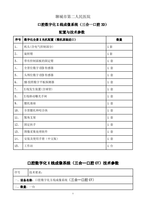
聊城市第二人民医院口腔数字化X线成像系统(三合一口腔3D)配置与技术参数口腔数字化X线成像系统(三合一口腔CT)技术参数注**:如果整机设计是移动式插拔单板,必须注明探测器一块板的单价合同内需满足的要求和售后1、另外需要满足:1.1完成与我院的PACS连接,图像信息共享,病人信息资料可通过医院的HIS/RIS系统显示在操作界面。
1.2另配诊断工作站一套,与我院PACS连接。
要求两个显示器,主屏为高清晰医用显示器。
主屏显示器3M医用显示器,I5处理器,4G内存,硬盘500G内存,2G显卡。
1.3生成图象能在其他任何激光相机上打印。
2.售后服务和技术培训:2. 1生产厂家的专业工程师提供安装及维修服务,并在500公里内有厂家维修站点2.3卖方应在中国境内设有备件库,具有≥50万美元规模的配件保税库,并保证10年的备件供应。
提供国内零部件免税仓库地址。
2.4设备安装调试验收合格后,卖方免费维修为1年,出保后每年免费保养两次,设备在运行期内出现故障时,卖方在接到买方通知后24小时内到场维修,否则每天赔偿1000元。
2.5提前对买方技术人员进行技术培训,免费提供2人外出(省级医院)学习15天,所产生的费用由卖方承担。
2.6提供设备中文操作和维修手册,提供完整的维修线路图2.7卖方技术人员须对安装、调试、维修、保养等事项向买方提供现场培训2.8卖方应免费提供本机今后开发的所有升级软件。
3.验收标准设备安装后,卖方必须按厂标或国际标准的验收标准、方法进行各项数据测试,并向买方提供安装调试报告和有关的测试数据.备注:参加投标的公司用多媒体形式产品介绍在5-8分钟内,另外介绍本型机器检查的典型病例5-8例,并说明使用的医院,病人的IP 号等信息。
2015年4月8日。
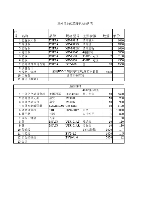
永泉山庄室外音乐预算
3300 280 960 1100 18000 800 50 180 180 1.7 1.5 12
金额
1610 1820 1610 3800 6300 4500 102000 121640 12000 15000 148640
33000 2800 9600 11000 18000 800 50 1800 1800 5100 1500 36000 121450
数量
1 1 1 1 2 1 68 3000
单价
1610 1820 1610 3800 3150 4500 1500 4
采用BVV2.5铜芯护套线,穿防水套管 包含安装固定
监控器材 1 一体化全球摄象机 美国冠军 FCZ-C480H 480线自动光圈、变焦 10 2 室外全球支架 嘉安 JM9001 10 3 室外全球云台 嘉安 JM8009 10 4 室外万能解码器 CAMERON CM-618F 10 5 硬盘录象机 TDI DVR-2012 12路 1 6 显示器 长城 17寸纯平 1 7 鼠标、键盘 飞豪 1 8 有源双绞线传输设备 BANLUN UTP101AT 发送端 10 9 有源双绞线传输设备 BANLUN UTP101AR 接收端 10 10 传输线 8芯双绞线 3000 11 电源线 BV2*1.5 1000 12 云台控制线 BV10*1.0 3000 13 合计
室外音乐配置清单及估价表
序号 名称
1 2 3 4 5 6 7 8 9 10 11 前置放大器 分区器 监听器 避雷器 功放 功放 室外带灯草地音箱 设备合计 线材、管材 工程费 合计(概算)
Hale Waihona Puke 品牌DSPPA DSPPA DSPPA DSPPA DSPPA DSPPA DSPPA
cmt2110单片机例程

cmt2110单片机例程全文共四篇示例,供读者参考第一篇示例:CMT2110单片机是一款性能优秀的嵌入式控制芯片,具有高性价比和稳定性好的特点。
它采用先进的Cortex-M4架构,拥有丰富的外设接口和强大的处理能力,适用于各种嵌入式控制和通信领域。
在CMT2110单片机中,通过合理编写例程程序,可以实现各种功能和运算,满足不同应用场景的需求。
一、CMT2110单片机的基本特点CMT2110单片机基于ARM Cortex-M4核心,主频可达200MHz,具有丰富的外设接口和内置的存储器。
它支持多种通信接口,如SPI、I2C、UART等,适用于各种外设设备的连接和数据交换。
CMT2110单片机具有多个定时器和PWM输出,可以实现精准的定时控制和PWM波形生成。
其内置的ADC和DAC模块可以实现模拟信号的采集和输出,适用于各种传感器和执行器的应用。
二、CMT2110单片机的例程编写编写CMT2110单片机的例程主要依赖于软件开发工具,如Keil、IAR等。
需建立一个新的工程,并选择CMT2110芯片型号和相关的外设驱动库。
然后,可以按照具体的需求编写各个功能模块的程序,最终在主函数中调用这些模块实现整体的功能。
可以编写一个LED闪烁的例程程序。
需要初始化GPIO口配置为输出模式,并设置一个定时器产生的中断来控制LED的闪烁频率。
然后,在中断服务函数中改变GPIO口的输出状态,从而控制LED灯的亮灭。
在主函数中初始化相关模块并进入主循环,实现LED的不断闪烁。
CMT2110单片机还支持串口通信,可以编写一个串口通信的例程程序。
需要初始化UART接口,并设置波特率等通信参数。
然后,在主函数中实现串口数据的发送和接收,可用于与PC机进行数据交互或与其他设备进行通信。
通过例程程序的编写,可以发挥CMT2110单片机强大的功能,满足各种应用需求。
三、CMT2110单片机的应用实例CMT2110单片机在各个领域都有广泛的应用,如通信、工控、物联网等。
欧姆龙cxon软件安装问题

楼主发表于: 2013-10-05 14:481| 小中大如图所示,在安装CX-ONE的时候相信有很大一部分人都遇到过类似的问题,我今天也遇到。
然后在网上收集教程求助,但知道的人和资料寥寥无几。
于是,便自己尝试。
因为下载下来的文件实在太多,刚接触怎么可能会知道如何安装呢。
经过失败几百次后,软件终于在本人的蹂躏下安静地安装ing。
,等待的结果当然是完美成功啦。
哈哈,废话少说,因为版本不尽相同导致存在的问题也不同,解决方案也不一样。
小弟我的观点仅供参考,但我确实是这样就解决问题。
一直出现“无法安装net framework ,请在重新安装CX-ONE前手动运行DISK里的XXXX 等”,如图所示,我的解决方法是少安装了这个东西。
如果大家有遇到这种问题的话,可以参考一下,对如果还不能解决的你深表遗憾。
我曾经遇到过也是没有安装NET 的提示,解决方法是启动了西门子,三菱,罗克韦尔的软件进程后就可以安装了光盘当中是有net framework 的安装文件的,一般这种情况可以试着手动安装一下.就可以了4安装。
5刚刚试了一下,确实解决了我的问题OMRON 的安装及使用问题解决方案2013-07-19 11:14:43|分类:|标签:|举报|字号订阅OMRON 的安装及使用问题解决方案欧姆龙(OMRON)集团为全球知名的自动化控制及电子设备制造厂商,掌握着世界领先的传感与控制核心技术,集团基本理念—企业是为社会做贡献的,而CX-one软件程序压缩包为omron所有自动化程序的集合,此软件包也是omron所属的最新产品,但由于当下利益的趋势和产品的推广成熟化,欧姆龙官网已不再支持免费下载,而早期产品不更新已慢慢退出市场,由于最近急需掌握好热了解omron 属下的PLC编程软件,搜索浏览了很多自动化网站及官网都下载或安装失败,功夫不负有心人,在工控人家园偶的一下载链接地址,经过四五个小时的解压安装测试排除问题后终于可以完美使用,为了使朋友们在急需时找软件和安装时遇到的问题无法解决,下面就详解一下安装和使用OMRN CX-one 的经验。
艾康视摄像机报价

2613.00
ICS-987H
1/3"超宽动态背光补偿彩色数码摄像机,最低照度0.02Lux/F1.2;水平480TV Line
3067.00
ICS-800CB
1/3"彩色/黑白自动转换摄像机,彩色0.01Lux/F1.2,黑白0.001Lux/F1.2;水平450TV Line
1040.00
ICS-748FB
1/3"黑白防暴半球摄像机F1.2时,最低照度=0.002Lux 600线可内置自动光圈镜头
1333.00
四、半球系列摄像机
ICS-801CB
1/3"彩色/黑白自动转换摄像机,彩色0.01Lux/F1.2,黑白0.001Lux/F1.2;水平450TV Line
1173.00
1/3"高分辩率彩色数码摄像机,最低照度0.02Lux/F1.2,水平480TV Line
1760.00
ICS-370
1/3"室外全天侯彩色一体化摄像机450线最低照度=0.01Lux,内置4~9手动二可变镜头(含支架)
1467.00
ICS-470
1/3"室外全天侯彩色一体化摄像机480线最低照度=0.02Lux,内置4~9手动二可变镜头(含支架)
1200.00
ICS-30IRL
1/3"彩色防水摄像机F1.2时, 420线IR ON/0Lux 24枚LED,可达距离20~25米
933.00
ICS-30IRH
1/3"彩色防水摄像机F1.2时,480线IR ON/0Lux 24枚LED,可达距离20~25米
杭州兆华 CRY2110型噪声传感器产品手册说明书
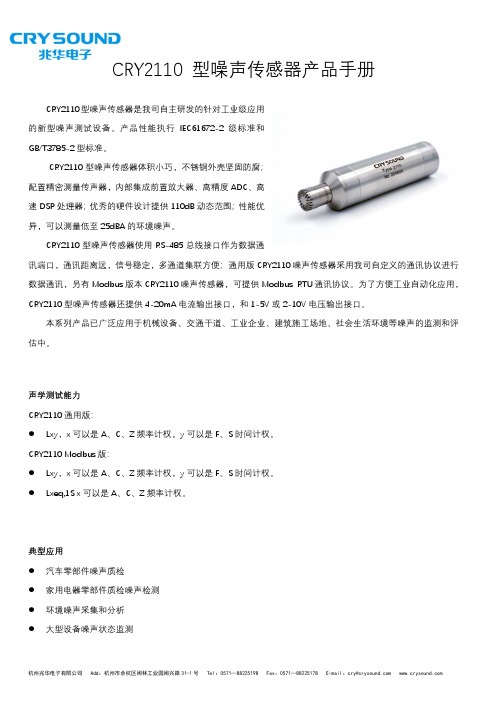
31-1CRY2110 型噪声传感器产品手册CRY2110型噪声传感器是我司自主研发的针对工业级应用的新型噪声测试设备。
产品性能执行IEC61672-2级标准和GB/T3785-2型标准。
CRY2110型噪声传感器体积小巧,不锈钢外壳坚固防腐;配置精密测量传声器,内部集成前置放大器、高精度ADC、高速DSP 处理器;优秀的硬件设计提供110dB 动态范围;性能优异,可以测量低至25dBA 的环境噪声。
CRY2110型噪声传感器使用RS-485总线接口作为数据通讯端口,通讯距离远,信号稳定,多通道集联方便;通用版CRY2110噪声传感器采用我司自定义的通讯协议进行数据通讯,另有Modbus 版本CRY2110噪声传感器,可提供Modbus RTU 通讯协议。
为了方便工业自动化应用,CRY2110型噪声传感器还提供4-20mA 电流输出接口,和1-5V 或2-10V 电压输出接口。
本系列产品已广泛应用于机械设备、交通干道、工业企业、建筑施工场地、社会生活环境等噪声的监测和评估中。
声学测试能力 CRY2110通用版:● Lxy,x 可以是A、C、Z 频率计权,y 可以是F、S 时间计权。
CRY2110 Modbus 版:● Lxy,x 可以是A、C、Z 频率计权,y 可以是F、S 时间计权。
● Lxeq,1S x 可以是A、C、Z 频率计权。
典型应用● 汽车零部件噪声质检 ● 家用电器零部件质检噪声检测 ● 环境噪声采集和分析 ● 大型设备噪声状态监测31-1号Tel:0571-********Fax:0571-********E-mail:*******************CRY2110型噪声传感器技术参数产品名称 CRY2110通用版 CRY2110 Modbus 版 通讯类型 我司自定义通讯协议Modbus 通讯协议执行标准 IEC61672-2级、GB/T3785-2级测量范围25~130dBA(因配套传声器灵敏度不同略有差异,以实际为准)动态范围 ≥110dB,无需量程切换传声器 CRY331低声压测试 选配传声器 CRY311(需要配套1/2转1英寸转接器)AD 采样率 48kHz 检波方式 全数字典型本底噪声 (电信号) 19dB(A)、21dB(C)、27dB(Z)测试频率范围 10Hz~20kHz 频率计权 A、C、Z 时间计权 F、S测试指标 Lxy(x=A/C/Z,y=F/S)Lxy、Lxeq,1S(x=A/C/Z,y=F/S) 数据刷新周期 50mS声压级输出 RS-485;4-20mA、1-5V 或2-10V 三选一供电电压 DC 5-24V (电流输出、电压输出时请选用高供电电压进行供电)外观尺寸 ɸ24.5mm×111mm重量 115g工作条件-10 ~ +50℃,相对湿度≤90%无凝露。
世界创新的2110短波便携电台Codan柯顿2110型便携电台极其轻便,是
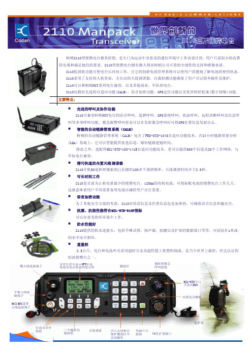
主要特点:柯顿2110型便携电台极其轻便,是专门为运动中及恶劣的通信环境中工作而设计的。
用户只需很少的花费即能 即实现和满足他们的要求。
2110型便携电台拥有澳大利亚柯顿公司可靠的全球性的支持和维修承诺。
2110低消耗功能可使电台长时间工作,且它的创新电池管理系统可以使用户清楚地了解电池的使用状态。
2110采用了友好的人机界面,全自动的天线调谐器,自我检测功能确保了用户可以简单操作及维护。
2110可以和柯顿NGT 系列电台兼容,以及其他商业、军队的电台。
2110还拥有先进的自适应功能(CALM)、语音加密功能、GPS 定位功能以及优异的轻松谈(数字消噪)功能。
●先进的呼叫及协作功能2110可兼容柯顿NGT 电台的语音呼叫、选择呼叫、GPS 系统呼叫、状态呼叫、远程诊断呼叫及信息呼 叫等多项呼叫功能。
紧急报警呼叫更是可以在发射紧急呼叫时可将GPS 位置信息发射出去。
●智能的自动链路管理系统(CALM )柯顿的自动链路管理系统(CALM )包含了FED-STD-1045自适应功能技术,在24小时链路质量分析 (LQA )基础上,它可以智能提供优选信道,缩短链路建链时间。
除此之外,选配件MIL-STD-188-141B 自适应功能技术,更可以提供600个信道及20个工作网络,与 军标电台兼容。
● 精巧快速的内置天线调谐器2110开机50毫秒即搜索到已存储的100多个调谐频率,天线调谐时间少于2.5秒。
●可长时间工作2110是目前为止耗电量最少的便携电台。
120mA 的待机电流,可使标配电池的便携电台工作几天。
这就意味着用户不再需要备用电池以减轻用户出行重量。
● 语音加密功能为了其他安全方面的考虑,2110对传送信息及位置信息也是加密的。
可确保语音信息传输安全。
●抗震、抗毁性能符合MIL-STD-810F 指标 可以在恶劣的坏坏境中工作。
●防水性能好2110提供的防水连接头,包括手咪话筒,扬声器,按键以及扩展的数据端口等等。
新华 数字化口腔X射线成像系统

新华数字化口腔X射线成像系统【用途】主要对口腔做X射线数字摄影检查。
【结构】控制盒、XC-100型X射线数字成像系统传感器、XC-200型X射线数字成像系统传感器【详细说明】控制盒技术参数尺寸(长*宽*高) 92*66*28mm电脑连接方式 USB2.0(full speed)电源供应(via USB) 5.0V(4.25V min)电流(via USB) 500mA max数字化 12 bits per pixer驱动免驱动(Windows下)XC-100型X射线数字成像系统传感器技术参数传感器外型尺寸(长*宽*高) 40*26*6mm有效面积(长*宽) 32.6*20.5mm有效像素(长*宽) 1450*910(1.3M)总像素(长*宽) 1454*918内在分辨率 22 lp/mm(22.5um)图像分辨率(70kVb) >12 lp/mmXC-200型X射线数字成像系统传感器技术参数传感器外型尺寸(长*宽*高) 44*32*6mm有效面积(长*宽) 36.0*27.0mm有效像素(长*宽) 1600*1200(1.9M)总像素(长*宽) 1604*1208内在分辨率 22 lp/mm(22.6um)图像分辨率(70kVb) >12 lp/mm【产品特点】控制盒技术参数尺寸(长*宽*高) 92*66*28mm电脑连接方式 USB2.0(full speed)电源供应(via USB) 5.0V(4.25V min)电流(via USB) 500mA max数字化 12 bits per pixer驱动免驱动(Windows下)XC-100型X射线数字成像系统传感器技术参数传感器外型尺寸(长*宽*高) 40*26*6mm有效面积(长*宽) 32.6*20.5mm有效像素(长*宽) 1450*910(1.3M)总像素(长*宽) 1454*918内在分辨率 22 lp/mm(22.5um)图像分辨率(70kVb) >12 lp/mmXC-200型X射线数字成像系统传感器技术参数传感器外型尺寸(长*宽*高) 44*32*6mm有效面积(长*宽) 36.0*27.0mm有效像素(长*宽) 1600*1200(1.9M)总像素(长*宽) 1604*1208内在分辨率 22 lp/mm(22.6um)图像分辨率(70kVb) >12 lp/mm【使用方法】主要对口腔做X射线数字摄影检查。
- 1、下载文档前请自行甄别文档内容的完整性,平台不提供额外的编辑、内容补充、找答案等附加服务。
- 2、"仅部分预览"的文档,不可在线预览部分如存在完整性等问题,可反馈申请退款(可完整预览的文档不适用该条件!)。
- 3、如文档侵犯您的权益,请联系客服反馈,我们会尽快为您处理(人工客服工作时间:9:00-18:30)。
____________________________________________MC21101.0A Single Channel Current-Limited Power SwitchFeatures● Single USB port power switch ● 100mΩ on -resistance● Input voltage range:2.7V-5.5V● Over-current, short and thermal protection ● 1.6A accurate current limiting ● 0.6ms typical rise time● ESD protection:4KV HBM, 400V MM ● Active high or active low enable ● Reverse Current Blocking● Ambient temperature range -40℃ to 85℃ ● Package: SOT-23-5、SOP-8● Lead Free finish/ROHS CompliantApplications● Telecom and network systems ● USB Power Distribution ● Notebook PCFigure 1: Pin Configuration of MC2110General DescriptionThe MC2110 is integrated high-side power switch optimized for self-powered and bus-powered Universal Serial Bus (USB) applications. The MC2110 is fully compliant with USB standards and is suitable for single USB port applications. The low on-resistance meets USB voltage drop requirements.When the output load exceeds current-limit threshold, MC2110 limits the output current to a safe level, which is typical 1.6A. Soft start and precise current limiting eliminate the momentary voltage drop on the upstream port that may occur when the switch is enabled into a heavy capacitive load. Besides, a thermal shutdown circuit is included to prevent catastrophic switch failure caused by increasing power dissipation when continues heavy loads or short circuit occurs. An under-voltage lockout (UVLO) circuit ensures that the device remains off unless there is a valid input voltage presents, and the enable input is compatible with both 3.3V and 5.5V logic.SOP-8/MSOP-8NN1N2N3M1/M2M3/M4Pin ConfigurationOrdering Information____________________________________________Typical ApplicationFigure 3: Typical Application of MC2110Block DiagramFigure 4: Functional Block Diagram of MC2110____________________________________________Absolute Maximum Ratings (Note 1)Note 1: Stresses greater than those listed under: “Absolute Maximum Rating”may cause permanent damage to the device. These are stress ratings only, and functional operation of the device at these or any other conditions beyond those indicated under “Recommended Operating Conditions” is not implied. Exposure to “Absolute Maximum Ratings”for extended periods may affect device reliability.Recommended Operating Conditions____________________________________________Electrical Characteristics(TA=25℃, VIN=5V, unless otherwise stated )________________________________________________________________________________________Typical CharacteristicsVIN=5V , TA=25℃, one switch section, unless noted.____________________________________________Turn-on, Turn-off characteristics (C in =10uF, C L =1uF, R L =10Ω) Turn-on, Turn-off characteristics (C in =10uF, C L =120uF, R L =10Ω)Current Limit Response (ramp load)Short Circuit ResponseTest CircuitFigure 5: Functional Characteristics Test Circuit____________________________________________Power SwitchThe power switch is a P-channel MOSFET with a low on-state resistance. Configured as a high-side switch, the power switch prevents current flow from OUT to IN and IN to OUT when disabled.DriverThe driver controls the gate voltage of the power switch. To limit large current surges and reduce the associated electromagnetic interference (EMI) produced, the driver incorporates circuitry that controls the rise times and fall times of the output voltage.Enable (EN)The logic enable pin disables the power switch driver, and other circuitry to reduce the supply current. The supply current is reduced to less th an 1μA or 2μA when a logic low (active high) or high (active low) is present on EN. A logic high (active high) or low (active low) input on EN restores bias to the driver and control circuit and turns the switch on. The enable input is compatible with both TTL and CMOS logic levels.Current SenseA sense FET monitors the current supplied to the load. The sense FET measures current more efficiently than conventional resistance methods. When an overload or short circuit is encountered, the current-sense circuitry sends a control signal to the driver. The driver in turn reduces the gate voltage and drives the power FET into its saturation region, which switches the output into a constant-current mode and holds the current constant while varying the voltage on the load.Thermal SenseThe MC2110 implements a thermal sensing to monitor the operating temperature of the power distribution switch. In an over-current or short-circuit condition, the junction temperature rises. When the die temperature rises to approximately 135°C due to over-current conditions, the internal thermal sense circuitry turns off the switch, thus preventing the device from damage. Hysteresis is built into the thermal sense, and after the device has cooled approximately 15 °C, the switch turns back on. The switch continues to cycle off and on until the fault is removed. The open-drain false reporting output (FLG) is asserted (active low) when an over-temperature shutdown or over-current occurs.Under-voltage LockoutA voltage sense circuit monitors the input voltage. When the input voltage is below approximately 2.0V, a control signal turns off the power switch.____________________________________________MC2110Power Supply ConsiderationsOver 10uF capacitor between IN and GND is recommended. This precaution reduces power supply transients that may cause ringing on the input and improves the immunity of the device to short-circuit transients. In order to achieve smaller output load transient, placing a high-value electrolytic capacitor on the output pin is recommended when the output load is heavy.Over-currentA sense FET is employed to check for over-current conditions. Unlike current-sense resistors, sense FET does not increase the series resistance of the current path. When an over-current condition is detected, the device maintains a constant output current and reduces the output voltage accordingly. Complete shutdown occurs only if the fault is presented long enough to activate thermal limiting.Three possible overload conditions can occur. In the first condition, the output has been shorted before the device is enabled or before VIN has been applied. The MC2110 senses the short and immediately switches into a constant-current output.In the second condition, a short or an overload occurs while the device is enabled. At the instant the overload occurs, high currents may flow for a short period of time before the current-limit circuit can react. After the current-limit circuit has tripped (reached the over-current trip threshold), the device switches into constant-current mode.In the third condition, the load has been gradually increased beyond the recommended operating current. The current is permitted to rise until the current-limit threshold is reached or until the thermal limit of the device is exceeded. The MC2110 is capable of delivering current up to the current-limit threshold without damaging the device. Once the threshold has been reached, the device switches into its constant-current mode.FLG ResponseThe FLG open-drain output is asserted when an over-current or over-temperature shutdown condition is encountered after 6-ms deglitch timeout, the output remains asserted until the over current or over-temperature condition is removed. Connecting a heavy capacitive load to an enable device can cause a momentary over-current condition; however, no false reporting on FLG occurs due to the 6-ms deglitch circuit. The MC2110 is designed to eliminate false over-current reporting. The internal over-current deglitch eliminates the need for external component to remove unwanted pulses. FLG is not deglitched when the switch is turned off due to an over-temperature shutdown.____________________________________________MC2110Mechanical DimensionsSOT-23-5____________________________________________MC2110SOP-8____________________________________________MC2110IMPORTANT NOTICECBC Microelectronics Co., LTD reserves the right to make changes without further notice to any products or specifications herein. CBC Microelectronics Co., LTD does not assume any responsibility for use of any its products for any particular purpose, nor does CBC Microelectronics Co., LTD assume any liability arising out of the application or use of any its products or circuits. CBC Microelectronics Co., LTD does not convey any license under its patent rights or other rights nor the rights of others.____________________________________________。